Welcome to RennTech.org Community, Guest
There are many great features available to you once you register at RennTech.org
You are free to view posts here, but you must log in to reply to existing posts, or to start your own new topic. Like most online communities, there are costs involved to maintain a site like this - so we encourage our members to donate. All donations go to the costs operating and maintaining this site. We prefer that guests take part in our community and we offer a lot in return to those willing to join our corner of the Porsche world. This site is 99 percent member supported (less than 1 percent comes from advertising) - so please consider an annual donation to keep this site running.
Here are some of the features available - once you register at RennTech.org
- View Classified Ads
- DIY Tutorials
- Porsche TSB Listings (limited)
- VIN Decoder
- Special Offers
-
OBD II P-Codes - Paint Codes
- Registry
- Videos System
- View Reviews
- and get rid of this welcome message
It takes just a few minutes to register, and it's FREE
Contributing Members also get these additional benefits:
(you become a Contributing Member by donating money to the operation of this site)
- No ads - advertisements are removed
- Access the Contributors Only Forum
- Contributing Members Only Downloads
- Send attachments with PMs
- All image/file storage limits are substantially increased for all Contributing Members
- Option Codes Lookup
- VIN Option Lookups (limited)


rick3000
-
Posts
267 -
Joined
-
Last visited
-
Days Won
1
Recent Profile Visitors


rick3000's Achievements
-

Wind Deflector (Center Piece) Frame removal
rick3000 replied to Ret06Aug17's topic in 986 Series (Boxster, Boxster S)
It isn't glued, the plexiglass is snapped into the black frame. Don't use a razor blade. You just need to "unsnap" one side, which can be a really difficult, but it can be done, the black frame will bend enough to remove the plexiglass. You should be able to see the plexiglass where it clips into the frame on each side, and you can pry it out with a flathead screwdriver. Just be careful the screwdriver doesn't slip and scratch the plexiglass. -
Switch Wiring - Dash Lights Voltage
rick3000 replied to ukchris's topic in 986 Series (Boxster, Boxster S)
It depends on the internals of the switch because they are not all the same, the standard hack uses a FWL switch which has the same problem with illumination. Unless you want to modify the internals of the switch, the only solution is to use a different switch. You can look up the internal wiring of the switches in the Bentley Manual, you want one that is internally identical to the convertible top switch. I recently updated my OBC hack that used the FWL switch with a convertible top switch to allow night illumination. You just need a small flathead screwdriver if you want to swap the top of the switches. -
DIY Manual Radiator Fan Switch w/ an OEM Switch DIY: Manual Radiator Fan Switch w/ an OEM Switch Fan Switch Part List $32 Defroster Switch, Matte Finish (996-613-134-10-A05) $25 Omron MY2K-DC12 Latching Relay $5 ATC Fuse Tap with .250 Male Disconnect $5 2.8MM Female Wire Terminal Various Male & Female Disconnects, Butt Connectors and Heat Shrink Tubing Various Lengths of 16AWG Wire Optional: $23 2-Butt Author rick3000 Category Boxster (986) - Mods Submitted 09/06/2019 12:42 PM Updated 09/07/2019 07:06 PM
-
DIY: Manual Radiator Fan Switch w/ an OEM Switch Fan Switch Part List $32 Defroster Switch, Matte Finish (996-613-134-10-A05) $25 Omron MY2K-DC12 Latching Relay $5 ATC Fuse Tap with .250 Male Disconnect $5 2.8MM Female Wire Terminal Various Male & Female Disconnects, Butt Connectors and Heat Shrink Tubing Various Lengths of 16AWG Wire Optional: $23 2-Button Batwing (996-552-335-02) Garage Switch Part List $47 996TT Targa Switch (996-613-119-10-A05) Various Male & Female Disconnects, Butt Connectors and Heat Shrink Tubing Various Lengths of 16AWG Wire Background The 986 is equipped with a left and right radiator fan. These fans have two speeds, high and low. The low speed fans come on whenever the AC is turned on, the high speed fans trigger when the coolant temp hits 215° F or the AC pressure hits a certain level (source Bentley Manual). While you could wire a switch to trigger the low or high fans, you can already trigger the low fans by turning on the AC, which is why this modification focuses on triggering the high fan speed. The point of installing a manual switch is to help cool your 986 before it hits the temperature threshold where the high speed fans would automatically come on. This could include track days where you want extra cooling and do not want to lose horsepower to the AC, or when you are in summer traffic and want to keep the car from heating up. Installing a manual switch should not override the normal operation of the high or low speed fans, it just lets you trigger them manually. If you leave the switch on when the car is turned off, the fans will automatically turn off after a short delay, and the fans will come on the next time the car is started. Preparation Start by disconnecting your battery, and placing a small block over the trunk latch to ensure the trunk does not accidentally close while the battery is disconnected. If you are installing the switch into the batwing trim piece: -Remove the carpeted trim on the driver and passenger side of the lower center console by grabbing the rear of the carpet and pulling out until the clips release, then slide the trim back and out. -Then remove the leather/leatherette trim on either side of the lower center console by grabbing it from the back and pulling out until the clips release, then slide it forward and off. -You can now remove the batwing by pulling on each side of the trim piece. -While not necessary I wanted room to work, so I also removed both cubbies from my lower center console. Remove the upper one first by pulling it out from each side, then the lower cubby is able to removed the same way. Step 1 - Wiring the Relays First you want to identify the high speed fan relays. They are located in the driver’s footwell above the fuse panel. The bottom row that is visible has four 53 relays, looking at the diagram the high speed relays are #20 and #22. Remove both relays. Now take a fuse tap and pliers to bend it to fit Pin 85 on the relay. The fuse taps I purchase required some filing to make them wide enough to over the relay pin. With the fuse tap installed, secure it to the relay. I decided not to use electrical tape because the relays can get quite hot while the car is running and I want to avoid a sticky mess, so I instead opted to secure them with a zip tie which I pulled tight with a pair of pliers. Note that the head of the zip tie is pointing down to make it easier to reinstall next to the other relays. Next take approximately two 6” wires and install two female disconnects on one end of each wire which attaches to the fuse taps, then combine both wires into a single butt connector. On the other side of the butt connect you want a few feet of wire that terminates in a disconnect (male or female depending on how you wire the relay and switch), mine ended with a female disconnect. This is the Pin 85 wire, that will be attached the latching relay later on. Route the wire to the center console, by pushing it up and around the plastic air tube above the driver’s footwell, then into the lower center console. Step 2 - Wiring the Switch and Latching Relay Since I was using the batwing trim piece I started by installing the switch into the batwing. This is tougher than you would think. With the switch in place but not “snapped in” I placed the batwing and switch on the edge of a table with the outside facing up. By using the edge of the table I could rest the batwing on the switch pins but let the batwing hooks which are longer hang off the edge. I think hit the trim piece with my hand until the switch snapped into place. I also placed thin cardboard on the table to avoid it getting scratched by the switch pins. The switch should sit flush with the batwing if installed correctly. The 2.8MM female disconnects are for the relay pins which are smaller than the switch pins, which accept normal female disconnects. To make the batwing removable, I used male and female disconnects. If you decided to do like me, instead of just hardwiring it into the car without any way to disconnect it, you would end up with four wires that need to be hooked up: Relay Pin 85, 12V Switched Power, Ground, Illumination Power. It is rather hard to describe the wiring in text so please review the diagram below. Switch Pin 1 - Relay Pin 14 Switch Pin 2 - Relay Pin 12 Switch Pin 3 - Illumination Power from dash Defroster Switch Pin 3 Switch Pin 4 - 12V Switched Power from Phone Connector Switch Pin 5 - Relay Pin 5 Relay Pin 9, 10, 11, 13 - Ground (I used the Phone Connector Ground) Relay Pin 11 - Pin 85 Wire Relay Pin 1 & 4 are not used Notes: -The Phone Connector 12V Switched power is Green/Black -The Phone Connector Ground is Brown -I wrapped the latching relay in some electrical tape to help “cushion” it but that probably isn’t necessary. -For the 4 Relays Pins that need to be grounded, I connected the wires using butt connectors. -The illumination power must come from the dash Defroster Switch Pin 3, this switch is wired differently than the others, and using a different source will cause the switch to always be on. Step 2.5 - Illumination Wiring I had previously tapped into the cigarette lighter for illumination power and ground, and the original plan was to use the same wiring. In most of the pictures in this guide you can see that the two switches share a wire, which was supposed to be the illumination wire. However, the defroster switch uses a different signal for illumination than every other other switch in the car. So you need to tap into the defroster switch in the dash for the illumination to work properly. Take a butter knife and insert it into the bottom of the switch panel, then carefully pry the trim piece out, it should unsnap and come free. The wiring hareness doesn't give you much room to work with, but you only need to remove the plug from the defroster switch. I used a flathead screwdriver to get it started, then carefully removed it the rest of the way, being careful not to damage my dash. As you can see, I chose to use another fuse tap on Pin 3 of the dash Defroster Switch. I secured it with a zip tie, and then ran a wire behind the center console to the lower center console. I removed the radio to route the wire, it may be possible without this step, but it would be difficult. Removing the radio requires inserting radio keys into the lower left and right slots. Step 3 - Installing the Batwing & Switch Slide the latching relay and wiring through the batwing opening. You may not be able to fit the latching relay through the batwing opening, so be prepared to disconnect the relay from the switch and plug it back in. With the wiring in place, connect the four loose wires: the Pin 85 wire that runs to the relays, the illumination power coming from the defroster switch, and the phone connector power and ground. Test the fan switch by reconnecting the battery and turning your key to the first position (power on), the latching relay requires 12V to operate, so it won’t work with the car off or the battery disconnected. The left side of the switch should trigger the high speed fans, and the amber LED in the switch should illuminate, the right side of the switch will stop the fans. Snap the batwing into place, and reinstall the lower center console trim in the reverse order. The Easy Way Follow Step 1 to tap the relays, then connect them to a simple on/off switch with the other end grounded to the phone connector or another ground point. You can stick the switch on the bracket under the steering wheel. I originally installed a simple switch this way and it worked fine, but I wanted a more clean and permanent installation. My last step is to install a 2.5" silver '986" decal on the batwing. Thank you to particlewave for his help figuring out the wiring on 986forum, and RennTech member Sandy that created the latching relay diagram I modified. You can also find this DIY on my personal website: blueboxster.com Note on the Engine Compartment Fan: You could also use this same switch to ground the engine compartment fan, you would just spice it in to the Pin 85 wire. I chose not to bother running a wire from the engine compartment fan relay in the rear trunk, because after using my durametric to review my oil, coolant and engine compartment temperatures and manually trigger the engine compartment fan, the engine compartment temperature does not appear to have any significant affect on the oil or coolant temperatures. Garage Switch Because I installed my fan switch in a 2-button batwing, I needed another switch to avoid using a blank (I have been on a quest to eliminate blank switches from my 986 since I got it). I decided to hardwire my garage door opener. I opened my garage door opener and used a wire to determine which two contacts needed to be connected to trigger the opener. I then soldered two wires to the two contacts, and drilled a hole in the side of the opener for the wires. You can test the opener by touching the two wires together to see if the garage door opens/ closes. Next I wired one wire to Pin 4, and the other wire to Pins 1 & 2. This allows both sides of the switch to open the garage door. If you have two garage doors you could wire one side of the switch to open one or the other. Pin 3 is the Illumination Power, and Pin 5 is the Illumination Ground. I installed disconnects on the two illumination wires and on the three garage switch wires to make the batwing removable, and to make changing the battery in my garage door opener easier.
-
Hi Everyone, I have a small wear spot on my '99 soft top that is about 1/8" in diameter. The tough waterproof layer under the outer fabric is still intact, but I would like to stop the fabric from wearing anymore and creating a hole. I use my hardtop 75% of the time, and I plan to replace the top with a glass one when the window finally breaks, so I am not looking to do an expensive repair on this top. I was thinking of putting some superglue over the wear spot, Loctite makes a flexible/fabric superglue that dries clear. Any thoughts on doing this? Would a better option be to carefully hand stitch it back together? Thanks, -Rick
-
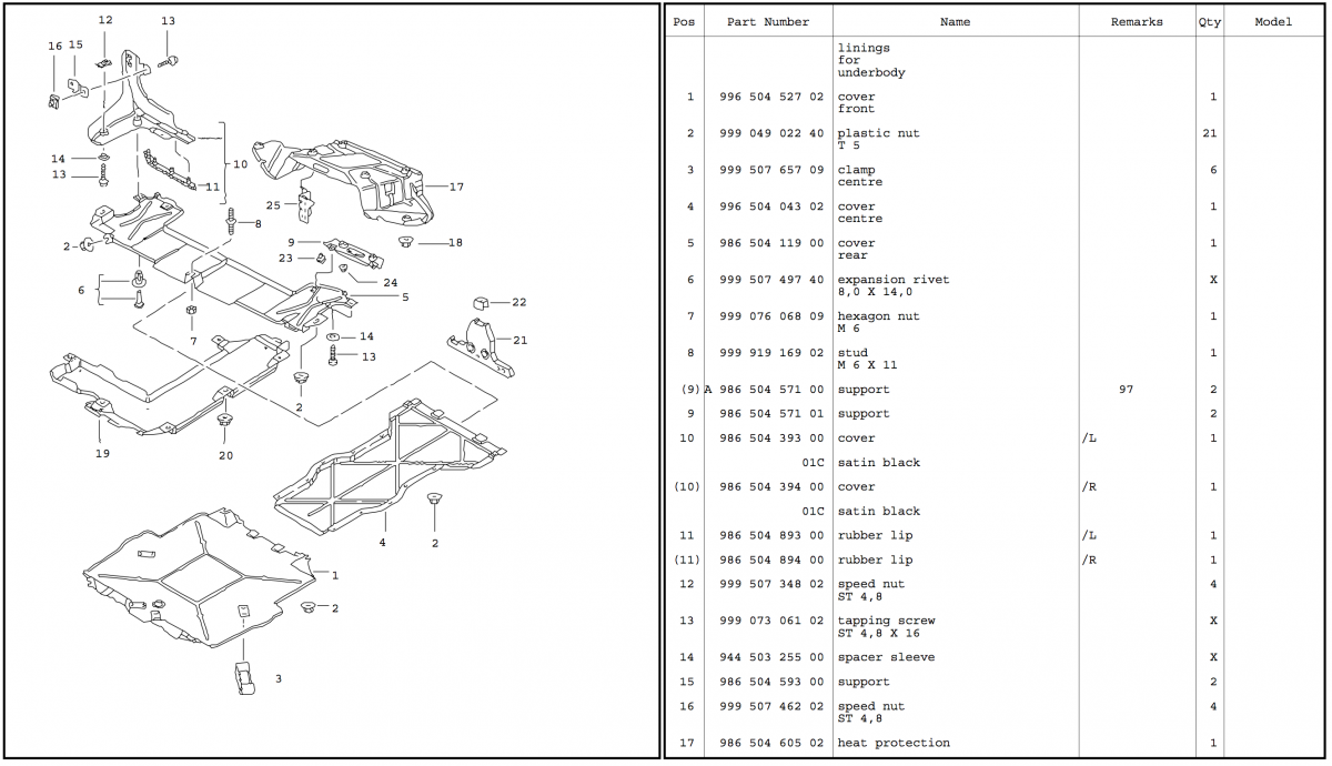
Hi Everyone, I was looking for some guidance for the fasteners for the rear underbody shield/cover. I got my car up on stands (first time under the car myself), and discovered the rear underbody shield is completely gone. (I am assuming my horrible mechanic broke it and never replaced it, one of the many reasons I am now working on the car myself). I know that I need: # 5 - 986 504 119 00 - Rear Underbody Shield/Cover #2 - 999 049 022 40 - Plastic Nuts x2 (one per side) #6 - 999 507 497 40 - Expansion Rivets x2 (one per side) #7 - 999 076 068 09 - M6 Hexagon Nut x1 (for the center stud, I need to check but I believe it is still there) Not Sure How Many of these are needed for just the rear cover? #23 - 999 591 699 02 - B4,8 Speed Nut x4? #13 - 999 073 061 02 - Tapping Screw ST 4,8 x 16 x? #14 - 944 503 255 00 - Spacer Sleeves x? The mounts for the cover are also very chewed up and I would like to replace them, can anyone confirm the part numbers/quantity? #9 - 986 504 571 01 - Cover Support x2 (same for each side?) #24 - 999 084 212 02 - M6 Nut x4? Thank you so much in advance to anyone to takes the time to respond! -Rick

-
Power Seat Electrical Connector
rick3000 replied to KevinH90's topic in 986 Series Part Number Requests
I did some sleuthing. It looks like this motor (Porsche PN: 99662433200)is similar to one used on a few Mercedes (PN 2108201242), they have the same manufacture name, Temic. After looking at some eBay pictures, the connector looks identical to Mercedes part A0175452126 or A0175452128, which when you search is called a pin bushing (no pictures). I did find another picture that looks identical, but the connector number is difficult to read, I think it is 728 025 300, and it doesn't turn up as a part. This is guess work, but for about $6 you can pickup PN: 017 545 21 26, and see if it works? Let us know how it goes. -
Power Seat Electrical Connector
rick3000 replied to KevinH90's topic in 986 Series Part Number Requests
Kevin, have you looked on the connector itself for any kind of number? These connectors are often VW or Mercedes parts that can be ordered separately. I could not find any images with a number or a separate part number, you can order the entire assemble for about $60. -
Porsche vs. Bentley Torque Discrepancies
rick3000 replied to rick3000's topic in 986 Series (Boxster, Boxster S)
And I'm sure that online system cost's an arm and a leg. Thanks again! -
Porsche vs. Bentley Torque Discrepancies
rick3000 replied to rick3000's topic in 986 Series (Boxster, Boxster S)
Thanks for the clarification Jeff! I am aware those less than reputable pdf's are outdated, but they have a few illustrations and diagrams that can't be found anywhere else. -
While I wait for the last few parts to arrive before I do a water pump replacement (among other service/upgrade items), I was reviewing my Bentley manual and the 986 Workshop Manuals (the pdf's ones that are around). I found a few discrepancies, and was hoping someone may be able to help clear them up. For the passenger seat, Porsche says to torque the Torx bolts to 15lb // 20Nm. Bentley says, 48lb // 65Nm. That's a pretty significant difference. For the motor mount, Porsche says to torque everything to 34lb // 46Nm, Bentley says 34lb // 46Nm for the mount, then 48lb // 65Nm for the yoke/bracket. Thanks again, -Rick
-
Spring Type Hose Clamps for Center Radiator Install
rick3000 replied to rick3000's topic in 986 Series Part Number Requests
Thanks Loren! I think I will try to source the clamps locally, once my Y-hose arrives. -
I am hoping someone familiar with the center radiator install for the 986 can help me out. I am looking for the part numbers for the six hose clamps used when installing the Y-hoses. The parts diagrams are not super clear, and I would like to order the spring type clamps as they seem to be the best type for hoses that expand/contract under pressure. Does anyone have the part numbers for these six spring type clamps? x2 Y-Hose to 'S' Hard Lines x2 Y-Hose to Side Radiators x2 Y-Hose to Center Radiator Thank you, -Rick
-
I recently asked BumperPlugs about getting a painted Non-Smoker Tray, they said it such an undertaking for them (ei - not cost effective), that they won't do it unless you are also buying the entire console. So you will have paint it yourself. Most Boxsters with a silver console are Arctic Silver, which is code X1. You can look here: http://www.986faq.com/4-0/#002
-
SOLVED: Realized it was about 40° in my garage, put a hair dryer on the amp plug and pins went right in. Thank you for the help kbrandsma!