Welcome to RennTech.org Community, Guest
There are many great features available to you once you register at RennTech.org
You are free to view posts here, but you must log in to reply to existing posts, or to start your own new topic. Like most online communities, there are costs involved to maintain a site like this - so we encourage our members to donate. All donations go to the costs operating and maintaining this site. We prefer that guests take part in our community and we offer a lot in return to those willing to join our corner of the Porsche world. This site is 99 percent member supported (less than 1 percent comes from advertising) - so please consider an annual donation to keep this site running.
Here are some of the features available - once you register at RennTech.org
- View Classified Ads
- DIY Tutorials
- Porsche TSB Listings (limited)
- VIN Decoder
- Special Offers
-
OBD II P-Codes - Paint Codes
- Registry
- Videos System
- View Reviews
- and get rid of this welcome message
It takes just a few minutes to register, and it's FREE
Contributing Members also get these additional benefits:
(you become a Contributing Member by donating money to the operation of this site)
- No ads - advertisements are removed
- Access the Contributors Only Forum
- Contributing Members Only Downloads
- Send attachments with PMs
- All image/file storage limits are substantially increased for all Contributing Members
- Option Codes Lookup
- VIN Option Lookups (limited)
Leaderboard
-0001-0001.thumb.png.17f5bb25bf8ec261a17c21e6321c8492.png)

Popular Content
Showing content with the highest reputation on 09/07/2018 in all areas
-
Hello Here's how to change wiper blades inexpensively buy just the rubber scraper at a store specializing in meter disassemble the brush to remove the 2 plastic caps on the ends of the brush with a small screwdriver prying to lift up the ends paw stuck rubber levering pull the rubber to change up the tab again to close the rubber blocks that give tips and here the brand new wipers Cayann friendly1 point
-
About 3 weeks back I started getting a CEL with a Code 0335 Crankshaft Position Sensor "A" Circuit. Upper Limit Exceeded. After clearing the code it kept coming back within a day or two and the car stalled on two occasions. Based on research on the forums, this seemed very much in line with sensor failures on 955's and a DIY existed for these model years, but not the 957. My 957 now has around 120k miles, and the engine runs incredibly well, aside from this one recent anomaly. I ordered a replacement sensor, from Pelican Parts which arrived the next day (very impressive service) :lowdown: thanks Pelican Crankshaft Sensor Brand: Bosch Note: Engine Type: 4.8L 4806cc V8 (3.78x3.27; 96.0x83.0) (2008 Porsche Cayenne S Sport Utility) Part #: 0-261-210-292-INT As there was no info available on this DIY for a 957 so I'm hoping the following will help others get this done easily when needed, and in particular so you can save the 2 hours extra it took me to figure out where and how everything was located, as well as how to get to it. Which I did while I was waiting for the new part to arrive However once that research was done, the actual job of replacing the sensor took about 45 minutes. The main challenge is that the connector is difficult to access as it is behind and below the fuel pump on the right hand side as you face the front of the car. Even with an inspection scope it was difficult to locate. It was only once I looked from under the car that I could see where it was located. Also the connector plug is attached to a rectangular section of plastic tubing/conduit on the wiring harness, by a clip which is very rigid. After multiple attempts to release this clip it broke off. I think give the location it gets very hot and over the years becomes brittle. You should remove the engine compartment trim at the rear of the engine for better access. I also borrowed a few pics of an engine on the web to mark the location: I also found that removing the harness from the engine made it easier to get my hands around the connector to get the two ends separated. Once you have the old sensor disconnected, attach the new one and and tape the end of the new sensor tip with some painters tape just for protection and slowly lower it down into the engine compartment. It will end up either side of the primary cat where it is easily accessible from below. Also let the old sensor cable drop into the engine bay as you will then extract it from below. Now move to underneath the vehicle. I only needed to jack up the front left of the vehicle (jack stand + jack for extra safety). No wheels need to be removed. Do not jack up the car before dealing with the connector at the top of the engine bay as it will make it difficult to reach. Between the connector and the sensor, the cable is secured at 3 locations. See pictures below. The cable is pretty easy to remove and secure from below the vehicle and it can be seen and accessed without removing any of the under trays (depending on your level of flexibility). The lowest retaining clip is a push in type retaining clip where you simply press the cable into the tensioned clip. The two upper retaining clips are circular in shape and hinge open and closed. With a built of gentle persuasion you can pull them open and the cable comes out easily. I could not get the uppermost one in the pics but it is similar to the 2nd one shown in the pics. The sensor is held in place with a single torx T5 screw. Once you have the old sensor off you can pull it out and put it aside and attach the new one. I suggest attaching the sensor first and the attaching the cable to the retaining clips. Very rewarding and inexpensive fix, and everything is back to normal. No more codes and the car runs beautifully!1 point
-
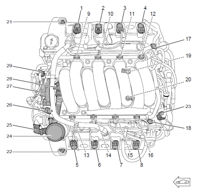 Top View 1- Ignition bar module, cylinder 1, bank 1 2 - Ignition bar module, cylinder 2, bank 1 3 - Ignition bar module, cylinder 3, bank 1 4 - Ignition bar module, cylinder 4, bank 1 5 - Ignition bar module, cylinder 5, bank 2 6 - Ignition bar module, cylinder 6, bank 2 7 - Ignition bar module, cylinder 7, bank 2 8 - Ignition bar module, cylinder 8, bank 2 9 - Fuel injector, cylinder 1, bank 1 (hidden) 10 - Fuel injector, cylinder 2, bank 1 (hidden) 11 - Fuel injector, cylinder 3, bank 1 (hidden) 12 - Fuel injector, cylinder 4, bank 1 (hidden) 13 - Fuel injector, cylinder 5, bank 2 (hidden) 14 - Fuel injector, cylinder 6, bank 2 (hidden) 15 - Fuel injector, cylinder 7, bank 2 (hidden) 16 - Fuel injector, cylinder 8, bank 2 (hidden) 17 - Inlet camshaft hall sensor, bank 1 18 - Inlet camshaft hall sensor, bank 2 19 - Knock sensor, bank 1 (hidden) 20 - Knock sensor, bank 2 (hidden) 21 - VarioCam solenoid valve, bank 1 22 - VarioCam solenoid valve, bank 2 23 - Ambient air solenoid valve 24 - Positive crankcase ventilation 25 - Three-way pressure valve 26 - Tank vent valve 27 - Throttle adjusting unit 28 - Positive crankcase ventilation heater 29 - Boost pressure control solenoid valve Front View 1 - Mass air flow sensor, right (hidden) 2 - Mass air flow sensor, left 3 - Charge air cooler, right 4 - Charge air cooler, left 5 - Boost-pressure sensor 6 - Boost pressure control solenoid valve (hidden) 7 - Boost pressure control valve (waste gate) - mechanical, right 8 - Boost pressure control valve (waste gate) - mechanical, left (hidden) 9 - Vacuum accumulator (in intake distributor) 10 - Overrun recirculating air solenoid valve (hidden) 11 - Overrun recirculating air valve - mechanical, left 12 - Overrun recirculating air valve - mechanical, right Rear View 1 - Secondary air valve - mechanical, left 2 - Ambient air solenoid valve 3 - Vacuum accumulator - integrated into intake distributor 4 - Coolant temperature sensor 5 - Secondary air valve - mechanical, right Underside View 1- Oil level and temperature sensor Oxygen Sensing 1- DME control module 2 - Secondary air injection pump, bank 1 3 - Secondary air valve - mechanical, bank 1 4 - Oxygen sensor in front of catalytic converter, bank 1 5 - Pre-catalytic converter, bank 1 6 - Oxygen sensor after catalytic converter, bank 1 7 - Main catalytic converter, bank 1 8 - Secondary air injection pump, bank 2 9 - Secondary air valve - mechanical, bank 2 10 - E-box in radiator tank with fuse and relay carrier 11 - Main catalytic converter, bank 2 12 - Oxygen sensor after catalytic converter, bank 2 13 - Pre-catalytic converter, bank 2 14 - Oxygen sensor ahead of catalytic converter, bank 2 Charge Measurement and Fuel Supply 1 - Mass air flow sensor, right 2 - Fuel injector, cylinder 1, bank 1 3 - Fuel injector, cylinder 2, bank 1 4 - Fuel injector, cylinder 3, bank 1 5 - Fuel injector, cylinder 4, bank 1 6 - DME control module 7 - Electric fuel pump, right 8 - EVAP canister 9 - Fuel tank 10 - Electric fuel pump, left 11 - Driver's door lock with switch for fuel pump supply 12 - Current distributor with cutoff relay under driver's seat 13 - KESSY control module 14 - E-box in radiator tank with fuse and relay carrier 15 - Pedal sensor 16 - Fuel injector, cylinder 8, bank 2 17 - Fuel injector, cylinder 7, bank 2 18 - Fuel injector, cylinder 6, bank 2 19 - Fuel injector, cylinder 5, bank 2 20 - Tank vent valve 21 - Mass air flow sensor, left 22 - Positive crankcase ventilation heater 23 - Throttle adjusting unit Charge Measurement and Fuel Supply - additional items for Turbo 1 - Mass air flow sensor, right 2 - Overrun recirculating air valve - mechanical, right 3 - Turbocharger with boost pressure control valve (waste gate), right 4 - Boost-pressure sensor 5 - Boost pressure control solenoid valve 6 - Vacuum pump for brake booster 7 - Intake distributor with integrated vacuum reservoir (used to control overrun recirculating air valves, for example) 8 - DME control module 9 - Brake booster 10 - E-box in radiator tank with fuse and relay carrier 11 - Pressure sensor for brake booster 12 - Ambient air solenoid valve 13 - Turbocharger with boost pressure control valve (waste gate), left 14 - Overrun recirculating air valve - mechanical, left Camshaft and Ignition Sensors 1 - Inlet camshaft vane-type adjuster, bank 1 2 - VarioCam solenoid valve, bank 1 3 - Ignition bar module, cylinder 1, bank 1 4 - Ignition bar module, cylinder 2, bank 1 5 - Ignition bar module, cylinder 3, bank 1 6 - Ignition bar module, cylinder 4, bank 1 7 - DME control module 8 - Hall sensor, bank 1 9 - Hall sensor, bank 2 10 - Ignition bar module, cylinder 8, bank 2 11 - Ignition bar module, cylinder 7, bank 2 12 - Ignition bar module, cylinder 6, bank 2 13 - Ignition bar module, cylinder 5, bank 2 14 - VarioCam solenoid valve, bank 2 15 - Inlet camshaft vane-type adjuster, bank 2 16 - Knock sensor, bank 2 17 - Knock sensor, bank 1 Temperature Control with Sensors 1 - Radiator fan, large (right) 2 - Ambient air temperature sensor 3 - Thermostat with housing 4 - Coolant temperature sensor 5 - DME control module 6 - Instrument cluster 7 - E-box in radiator tank with fuse and relay carrier 8 - Additional coolant circulation pump (also controlled by the DME in turbo engines only) 9 - Radiator fan, small (left)1 point