Welcome to RennTech.org Community, Guest
There are many great features available to you once you register at RennTech.org
You are free to view posts here, but you must log in to reply to existing posts, or to start your own new topic. Like most online communities, there are costs involved to maintain a site like this - so we encourage our members to donate. All donations go to the costs operating and maintaining this site. We prefer that guests take part in our community and we offer a lot in return to those willing to join our corner of the Porsche world. This site is 99 percent member supported (less than 1 percent comes from advertising) - so please consider an annual donation to keep this site running.
Here are some of the features available - once you register at RennTech.org
- View Classified Ads
- DIY Tutorials
- Porsche TSB Listings (limited)
- VIN Decoder
- Special Offers
-
OBD II P-Codes - Paint Codes
- Registry
- Videos System
- View Reviews
- and get rid of this welcome message
It takes just a few minutes to register, and it's FREE
Contributing Members also get these additional benefits:
(you become a Contributing Member by donating money to the operation of this site)
- No ads - advertisements are removed
- Access the Contributors Only Forum
- Contributing Members Only Downloads
- Send attachments with PMs
- All image/file storage limits are substantially increased for all Contributing Members
- Option Codes Lookup
- VIN Option Lookups (limited)
Leaderboard
-0001-0001.thumb.png.17f5bb25bf8ec261a17c21e6321c8492.png)


Popular Content
Showing content with the highest reputation on 09/21/2018 in all areas
-
1 point
-
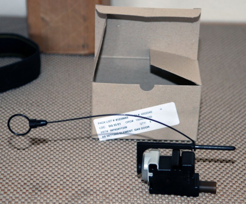
Well, I wasn't aware that there was an emergency cable for the gas fill door. Speaking of emergency cables, I took my trunk cable and routed through the inner aluminum bumper and attached it to the plug cover the towing eye. I know where it is and easy to get to.1 point
-
Trying to figure all this out. I have a 2009 Carrera 4. Manual states AWD controlled fluid and PDK clutch fluid at 60K, and transmission fluid and final drive fluid at 120K I really just want to know what to change, with what fluid, and when and Porsche could not make it more complicated. 1 - PDK clutch fluid - about 5L of the FFL3 stuff and you need a PIWIS - check - dealer did this 2 - AWD controlled stuff - in the repair manual they have a clutch and a differntial listed on the front final drive - with a capacity of .9L - what fluids go in there? 3- final drive - capacity 1.5L, needs changed at 12 years/120,000 miles - what fluid goes in there? And this is part of the PDK transmission? So there are 3 fluids in the PDK? 4 - PDK transmission fluid - capacity 9L (change capacoty of 4.5L) needs done at 12yr/120,000 miles - what fluid goes in there?1 point
-
Building Your Own Car Ramps I've been disappointed by off-the-shelf car ramps from auto parts stores and even high-end specialty catalogs. They all seem to be too low to the ground, to narrow for big 'monster meats', too steep of an approach angle so they won't fit under a low air dam or exhaust, and generally flimsy. So I built my own, to my own specifications. My requirements were: 1) extra width and no side channels for enhanced stability and to accomodate extra-wide tires 2) shallow approach angle for vehicles with low ground clearance 3) extra height for more working space under vehicles with low ground clearance 4) very high strength for my own peace of mind Disclaimer: Following is a description and photos of my own design. I used brand-new, premium, non-treated lumber and an entire (small) box of 2-1/2" galvanized nails. I built them carefully and made sure every interface was joined by several nails for extra safety. I believe my ramps could hold up a semi truck. But, I make no claims as to their suitability for any such purpose, and if you build your own ramps based on my design using your own materials, techniques, tools, and ideas, you do so at your own risk. If you use such ramps to work on your car, you do so at your own risk. Safety first! There are many Porsches in the world, but only one you... Materials Required: 1. Four (4) industry-standard premium "2x10" boards, each measuring eight (8) feet in length 2. Two (2) industry-standard premium "2x4" boards, each measuring twelve (12) feet in length 3. One (1) industry-standard premium plywood, 3/4" thick, measuring approximately seven (7) feet by two (2) feet 4. One (1) box (approx qty=200-300) galvanized nails, 2-1/2" in length (drywall screws may be substituted) 5. Four (4) heavy-duty grab-handles (plated, galvanized, or painted) (optional, but recommended - these are heavy!) Tools Required: 1. Table saw or circular saw 2. Hand saw 3. Hammer 4. Square 5. Pencil 6. Measuring tape 7. Straightedge or chalk line 8. Screwdriver or power driver 9. Partner to help 10. Intermediate expertise in woodworking Basic Diagram: Procedure: 1. On each 8' section of 2x10, measure 24" from each end of the board, and draw a diagonal line between the points. Cut along this line to produce two (2) main boards from each single 8' 2x10 board. Each main board will have the shape of the side of the ramp. Each ramp will require at least four (4) main boards. (Optional - for increased strength and significantly increased weight, construct each ramp out of seven (7) main boards, thus making each ramp completely solid all the way through.) 2. If making the ramps as shown, cut 2x4 spacer blocks equal in length to the "10-inch" width of the 2x10 main boards. Create an alternating arrangement of main board 1, 2x4, main board 2, 2x4, main board 3, 2x4, then main board 4. 3. Cut smaller spacer blocks to fit between the main boards under the ramped section. These are critical to the long-term strength and stability of the ramp section, so do not leave these out. 4. Assemble the base sections with lots and lots of nails and/or drywall screws. Don't be afriad to use a lot. 5. Cut the facing out of your plywood. Mitre the ends of the plywood to make a smooth transition between the ground and the ramps. Mitre the joint between the facing on the ramp section and the facing on the top section. Assemble facing to base sections with plenty of nails/drywall screws. 5. VERY IMPORTANT: Cut end stop blocks out of your 2x4 stock to make "stop blocks" at the tops of the ramps. These act to give you notice that your tires are at the ends of the ramps. If you do not have these stop blocks, you may accidentally drive the vehicle right off the end of the ramps. If you have a hard time feeling when the tires contact the blocks, stack up two (2) thicknesses of 2x4s at the ends to make your stop blocks. Make sure the two thicknesses still clear the air dam/exhaust/etc. Assemble to ends of flat top sections as shown in the diagram with liberal use of nails and/or drywall screws. 6. Optional, but very very handy: Affix heavy-duty grab-handles in desired locations. Note the positions and orientations of the grab handles of my ramps. One set is to carry them around and move them when in storage (stored on their ends for minimal footprint), and the other is to move the ramps into position at the vehicle. Example Photos: Handles used to move/store ramps: Handles used to adjust position of ramps: You can either reply to this post or contact me directly at dphil66@hotmail.com if you have questions. Happy motoring!1 point
-
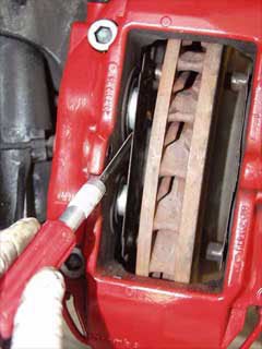 Note: Part numbers sometimes change without notice. Always double check with your supplier that you have the latest part numbers. Parts you will need: 1 set 996 352 949 03 Front Brake Pads - Porsche (Pagid "S" Pads - Dark Blue - T5104SRS14) 1 set 996 351 088 01 Front Vibration Dampers for Brake Pads (recommended) 2 ea 996 351 959 00 Front Pad Repair Kit (consisting of 2 bolts, springs and securing clips) 2 sets 996 612 365 00 Front and Rear Wear Sensors (if needed) 1 set 996 352 939 03 Rear Brake Pads - Porsche (Pagid "S" Pads - Dark Blue - T5105SRS14) 1 set 964 352 096 01 28 mm Rear Vibration Dampers for Brake Pads (recommended) 1 set 964 352 096 00 30 mm Rear Vibration Dampers for Brake Pads (recommended) 2 ea 996 352 959 00 Rear Pad Repair Kit (consisting of 2 bolts, springs and securing clips) Tools you will need: Jack 19 mm socket for wheel bolts Brake Parts Cleaner (do not use other cleaners) Needle Nose Pliers Punch (for driving the pins out) Hammer or soft mallet Caliper Spreader or large Water Pump Pliers Note: The brake pads must be replaced (both sets of pads per axle) if the brake pad warning indicator lights up, but no later than when there is a residual pad thickness of 2 mm. If brake pad wear is indicated by the warning light, the warning contact sensor (sender including wire and plug connection) must also be replaced. Replacing the warning contact sensor can be avoided by replacing the brake pads no later than when the pad thickness is 2.5 mm. Warning contact sensors with a worn wire core must be replaced. However, if only the plastic part of the warning contact is worn, replacement is not necessary. Also, do not disassemble the caliper when changing the vibration dampers (or painting the calipers) as Porsche does not sell inner seal kits. Jack up the vehicle at the lift points provided and remove the a wheel (you will need to do this for each wheel). Visually inspect the brake pads for wear. The wear limit is reached when the pad has a residual thickness of 2 mm (or less). Front Pad Replacement Remove the retainer (arrow) and extract the retainer pin inwards. Pull out the warning contact wire on the brake caliper and remove the warning contacts from the brake pad plates. Remove brake pads with a brake pad puller or use the water pump Pliers to spread the pads. (Photos are courtesy of Greg Heumann) Important Notes: Pull out brake pads together with the vibration dampers. If this is not possible (depending on wear of the brake pads), use a spatula to detach the vibration dampers from the brake pad plate before removing the pads. In both cases, first set back the brake pads as far as possible with the piston resetting fixture. If necessary, first remove some brake fluid by suction from the brake fluid reservoir. If necessary, carefully push back the piston to its original position. Fit new vibration dampers in the pistons. Do this by removing protective film from the vibration dampers before installation. Insert the brake pads. Caution: The pad backing plates (rear side of the brake pads) must not be greased. Note: If you are using Pagid (or some other 3rd party pads) you will likely have to drill the pad for the wear sensors. Just look at the old pads and drill the sensor holes in the same location. Fit new expanding spring, new retaining pin and new retainer (retaining bracket). These parts are available as a repair set and must be 'renewed' each time the pads are changed. Insert the warning contact wire and warning contacts. Firmly press the brake pedal several times with the vehicle stationary so that the brake pads assume their fit in accordance with the operating state. Next, check and, if necessary, correct the brake fluid level. Bedding in the brake pads New brake pads require a bedding-in period of approximately 125 miles. Not until then do they achieve their best friction and wear coefficient. During this period, the brakes should be subjected to full stress only in emergencies when traveling at high speed. ------------------------------------------------------------------------------------------------------------------------------ Rear Pad Replacement Remove the retainer (arrow) and extract the retainer pin inwards. Pull out the warning contact wire on the brake caliper and remove the warning contacts from the brake pad plates. Remove brake pads with a brake pad puller or use the Water pump Pliers to spread the pads. Important Notes: Pull out brake pads together with the vibration dampers. If this is not possible (depending on wear of the brake pads), use a spatula to detach the vibration dampers from the brake pad plate before removing the pads. In both cases, first set back the brake pads as far as possible with the piston resetting fixture. If necessary, first remove some brake fluid by suction from the brake fluid reservoir. If necessary, carefully push back the piston to its original position. Fit new vibration dampers in the pistons. There are 2 sizes of vibration dampers. The lower piston is 28 mm (smaller) and upper piston is 30 mm (larger). Be sure you get them in the right places. As you install them you will need to remove the protective film from the vibration dampers. Insert the brake pads. Note: The pad backing plates (rear side of the brake pads) must not be greased. Fit new expanding spring, new retaining pin and new retainer (retaining bracket). These parts are available as a repair set and must be 'renewed' each time the pads are changed. Insert the warning contact wire and warning contacts. Firmly press the brake pedal several times with the vehicle stationary so that the brake pads assume their fit in accordance with the operating state. Finally, check and, if necessary, correct the brake fluid level. Bedding in the brake pads New brake pads require a bedding-in period of approximately 125 miles. Not until then do they achieve their best friction and wear coefficient. During this period, the brakes should be subjected to full stress only in emergencies when traveling at high speed.1 point
 -
 Note: Part numbers sometimes change without notice. Always double check with your supplier that you have the latest part numbers. (Edit - July 25, 2006 - Updated the clutch bleeding procedure to the latest procedure as outlined in supplement 98 of the Carrera Service Manual - Loren) Parts you will need: 1 liter (minimum) 000 043 203 66 Porsche DOT 4 Brake Fluid or equal (ATE Gold or ATE Super Blue) Tools you will need: Jack 19 mm socket for wheel bolts Motive Power Bleeder (or equal) image Needle Nose Pliers 11 mm wrench for brakes; 9 mm for clutch slave (sizes vary from car to car but they are usually 9 mm or 11 mm) Plastic tubing and waste container (at least 1 liter) Jack up the vehicle at the lift points provided and remove the rear wheel (you will need to do this for each wheel). Remove the cap on the master cylinder reservoir. Remove the plastic screen using a pair of needle nose pliers. This can be a little bit challenging but it will pop off (be careful with the brake fluid.. it eats paint!) Use a syringe (or turkey baster... just don't reuse it) and suck out as much of the old fluid as possible. Fill the master cylinder reservoir with new fluid. Put the rest in the power bleeder. Screw the cap that came with the power bleeder onto the master cylinder reservoir. Put the pressure cap with the pump handle on the power bleeder and pump it up to just under 20 psi - do not go over 20 psi! Bleed order - Right rear, Left rear, Right front, Left front. Place your drain tube over the outside bleed nipple and in the bottle (remember it will need to hold a liter when you are done). Bleed the outer bleeder valve first. Open each bleeder valve until clear, bubble free brake fluid emerges. Take care to bleed at each brake caliper and at both bleeder valves. Carefully tighten the bleed screw. Wipe off the area and replace the rubber protective cap over the bleed screw. Repeat steps 8-10 for the interior bleed screw. Then reinstall the wheel and move on to the next wheel. Note: It makes sense to check the pressure and amount of fluid in the tank between wheels. Running out of fluid means starting over and getting air out. Optional Clutch Bleeding This is best done when you are bleeding the left (driver's side) rear wheel as the clutch bleed valve is mounted high above the axle on the transmission. Push the clutch pedal in by hand (very slowly) and use a long piece of wood to hold the pedal down. I wedged the other end (of the wood) between the seat and door frame -- with plenty of soft padding to avoid scratches. A second option is to have a 2nd person sit in the car and keep the clutch pedal FULLY depressed. Open the clutch bleeder valve until clear, bubble free brake fluid emerges (at least 30 seconds according to Porsche). Remove the wood. Then, pump the pedal again very slowly by hand for a further 60 seconds. After pressing the pedal down fully about 10 to 15 times, leave the pedal in its normal position. After allowing a fill time of 90 seconds, check that no more air bubbles appear at the bleeder valve (use a collecting bottle with a transparent hose). Then close the bleeder valve. Wipe off the area and replace the rubber protective cap over the bleed screw. You may notice that the clutch pedal does not return... so carefully pull it up (slowly) to it's normal position. Then depress it (slowly) a few (at least 5) times. In a few cycles the feel should return. [*]Torque the wheels bolts to 96 ftlb. (130 Nm). [*]Do a final check on the brake fluid level and top up if needed.1 point