Welcome to RennTech.org Community, Guest
There are many great features available to you once you register at RennTech.org
You are free to view posts here, but you must log in to reply to existing posts, or to start your own new topic. Like most online communities, there are costs involved to maintain a site like this - so we encourage our members to donate. All donations go to the costs operating and maintaining this site. We prefer that guests take part in our community and we offer a lot in return to those willing to join our corner of the Porsche world. This site is 99 percent member supported (less than 1 percent comes from advertising) - so please consider an annual donation to keep this site running.
Here are some of the features available - once you register at RennTech.org
- View Classified Ads
- DIY Tutorials
- Porsche TSB Listings (limited)
- VIN Decoder
- Special Offers
-
OBD II P-Codes - Paint Codes
- Registry
- Videos System
- View Reviews
- and get rid of this welcome message
It takes just a few minutes to register, and it's FREE
Contributing Members also get these additional benefits:
(you become a Contributing Member by donating money to the operation of this site)
- No ads - advertisements are removed
- Access the Contributors Only Forum
- Contributing Members Only Downloads
- Send attachments with PMs
- All image/file storage limits are substantially increased for all Contributing Members
- Option Codes Lookup
- VIN Option Lookups (limited)


tony z
-
Posts
38 -
Joined
-
Last visited
Content Type
Profiles
Events
Forums
External Paint Colors
Downloads
Tutorials
Links Directory
Collections
Store
Posts posted by tony z
-
-
Thanks that is what I thought however the fuel fuse (position C4) is a 30 amp fuse so I am wondering if my relay jumper fuse should be 30 amps instead of 15 . Maybe the fuel pump when it intially tries to start is drawing enough current to blow the 15 amp jumper fuse ?
cheers
-
Hi
I am trying to remove the fuel from my tank and have made a relay jumper that goes between points 87 - 30 of the relay socket.
The Bentley book says to place a 15 Amp fuse in the jumper cable however that fuse blows when the jumper is inserted into the relay points. I see that the Dempsey 101 projects (fuel pump) has no such fuse. Should I be using a fused or unfused jumper ?
Cheers
-
Thanks Porsche librarian
I have 11 technical updates last one is dated 4/12/2007. If there are later ones I would be interested.
Thanks
-
Thanks Loren
Page 87 is in section 10 (engine and crankcase)
Page 235 is in section 13 (Engine, crankcase and pistons) however page 235 indicates on the right hand top corner "10"
-
Thanks Loren
Page 87 is in section 10 (engine and crankcase)
Page 235 is in section 13 (Engine, crankcase and pistons) however page 235 indicates on the right hand top corner "10"
-
The workshop manual (Technical Manual 911 Carrera (996) Group 1 Engine) including technical updates supplied by the Porsche librarian. I also have the Bentley and Dempsey books (101 Projects).
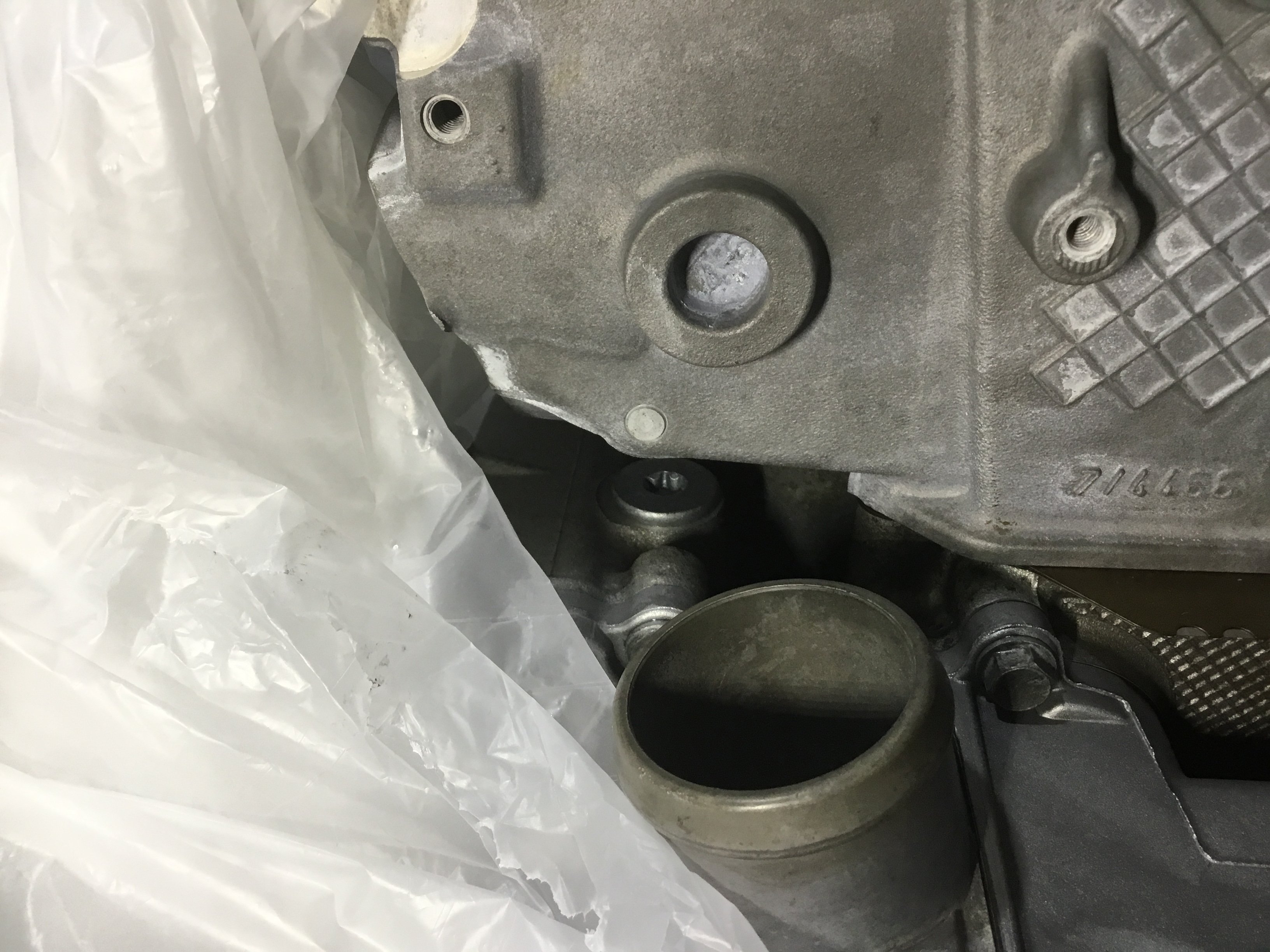
The attached picture shows bolt # 7 with the cylinder head above it.
The cylinder head is just sitting on the crankcase and as you will see from the photo it all but obscures access to the bolt head. Bolts # 8 and 9 are not obscured when the cylinder head 1-3 is in situ.
The Technical manual is providing contradictory information. Page 87/821 and page 235/821 refers
Thanks for your assistance

-
Hi
My engine has M96/ ....then 10 digits. The first five digits align with the Porsche documentation that came with the car.. I presume the remaining 5 digits are for the transmission ?
On another matter the work shop manual says that bolts # 7, 8 and 9 (https://nemigaparts.com/cat_spares/pet/porsche/996/21/101050/) are not supposed to be torqued until the both cylinder heads are torqued. The manual later on says that bolt # 7 must be torqued before the 4 -6 cylinder head is torqued. It would seem impossible, from an access perspective, to torque bolt # 7 after the head is on the crankcase.
Am correct in assuming that I must torque bolt # 7 it before 4 -6 cylinder head is torqued ??
thanks
-
Hi
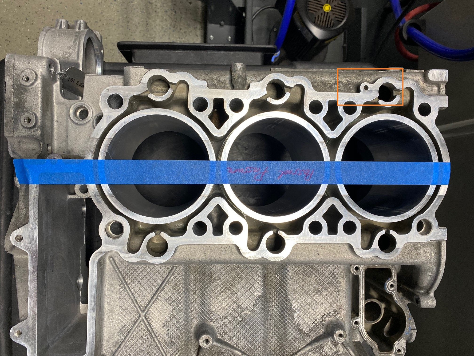
I obtained the answer from a friend at LN engineering. The attached picture denotes the hole for the 5X12 roll pin. My engine doesnt have the hole even though the VIN/PET says it does.
-
Thanks
Pelican parts helpfully checked against my VIN and the roll pins are listed. However there are no 5 milimeter diameter holes for the 5X12 roll pin in either the cylinder head or crankcase half in the area indicated by # 35. My engine does however have 2 holes for the 17X18.5 dowel pins (# 11) on each cylinder head/crankcase half.
I am not sure what to do at this juncture !!
-
Thanks.
I tried entering my Vin into the website you provided but as Loren suggested it doesnt work.............So it seems I will have to get advice from a dealership in my area.
-
Thanks very much Loren.
I was using the a PET PDF which was kindly given to me by a guy from Pelican Parts
I guess I will have to call the dealer unless someone in Forum knows anything further.
I cant see where the roll pin would fit, there simply isnt a 5mm hole in the crankcase or cylinder head surfaces
Cheers
-
Hi
This is probably a stupid question. PET (page 38) specifies a 5 X 12 roll pin (part number 900 095 137 01). The work shop manual (page 86) specifies no such pin and nor did I see any such pin when the engine was being taken apart. I have a 2003/3.6 litre 996.
I presume that this roll pin isn't needed for my engine ?
Thanks
-
Jake has a video on Youtube that shows how to use an endoscope thru the oil sump to access if cylinder scoring is, or has, occurred. I would suggest that you should check it out and determine whether you want to do that. Scopes are quite cheap and accessing the sump is quite easy.
cheers
-
-
Hi
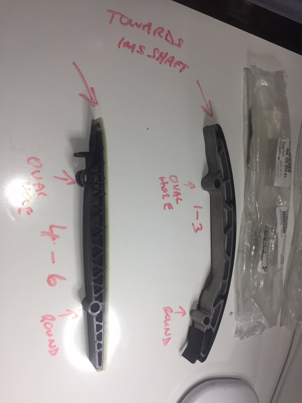
I have question on proper orientation of the timing chain rails for cylinders 1-3 and 4-6...the attached picture refers.
I have indicated what I think their orientation should be in relation to the IMS shaft in the attached picture.
If you enlarge the picture you will see that both bolt holes nearest where I have written "IMS shaft" are oval and the ones furthest away are round.
Please advise if I have the orientation correct

Much appreciated
-
To complete the loop. I had it checked for balance and it was near perfect. Thanks for your advice.
I now on to installing the new timing chain guide rails. Unfortunately Its been such a long time that I cant remember the orientation of the two rails which have two retaining bolts. I have two new rails so I know which cylinder banks (1-3 and 4-6) they are supposed to go in.
I presume the most tapered end of each rail which has the oval bolt hole should be inserted towards the crankshaft ?
cheers
-
The web link below has Flat 6 Innovations stating that they "weld and/ or pin every sprocket and drive. Overkill does not exist when I assemble one."
https://rennlist.com/forums/996-forum/928373-has-anyone-had-their-ims-gears-welded.html
My M96 IMS shaft has the larger sprocket pinned and 3 weld points on the two smaller sprockets. Each weld length is pretty much equal and spaced roughly equally around the sprocket circumferences
What is not clear is whether or not the shaft would need to be balanced after the tig welds are applied.
I intend to use the LN Engineering IMS Solution bearing. Not sure if that would make a difference as to whether the shaft should be balanced after welding or not ?
Your expert advice would be very much appreciated.
Thanks
-
Thanks, that makes perfect sense as did you explanation of torque to yield..
The Porsche workshop manuals are a bit confusing........... I still havent been able to figure out what I am supposed to check with respect to the sealing balls on the crankshaft carrier. There are 6 present but I have no idea what is meant by them being correctly caulked !!
-
Yes I agree !!
-
Hi again
When I asked this forum about their recommendations I had already logged a message with Pelican Parts on the micro encapsulated bolt issue.
I was more than happy with the two responses I received from this forum. For that many thanks.
I wish I had not asked Pelican !!. They just came back to me saying;
....... Best practice is to replace them with new microencapsulated ones. None of us have enough experience with reusing them to make a solid recommendation.
I intend to take your technical advice but thought you should know what Pelican had to say. .
cheers
-
Hi
Page 89 of the Carrera (996) Group 1 workshop manual has a diagram which illustrates where the drei Bond sealant is to be applied to crankcase half 4 – 6. This diagram differs from the one on page 232.
Does any know which diagram is correct for a 2003 996 3.6 litre engine. Additionally it seems a bit strange that both diagrams omit applying sealant in certain areas.
Aside from that both diagrams are a bit fuzzy. Maybe there is a better quality copy somewhere on line ?
Thanks for your assistance
-
Thanks. for that. I shall proceed as you recommend unless someone else has a contrary view !
cheers
-
Thanks....I meant to note that I intend to reuse the old bolts and just apply loctite .....is that Ok to do ?.. The bolts are the ones that attach to the crankshaft carrier to hold the chain guide and black plastic oil separato
thanks
-
sorry I meant loctite 243 or 263
fuel removal
in 996 Series (Carrera, Carrera 4, Carrera 4S, Targa)
Posted
Thanks Loren. According to the Bentley manual the fused rating was 25 amps up until 2000. It then changed for 2001 - 2005 models to 30 amps.
So I guess I assume that the relay jumper doesnt need to be fused ?
Cheers