Welcome to RennTech.org Community, Guest
There are many great features available to you once you register at RennTech.org
You are free to view posts here, but you must log in to reply to existing posts, or to start your own new topic. Like most online communities, there are costs involved to maintain a site like this - so we encourage our members to donate. All donations go to the costs operating and maintaining this site. We prefer that guests take part in our community and we offer a lot in return to those willing to join our corner of the Porsche world. This site is 99 percent member supported (less than 1 percent comes from advertising) - so please consider an annual donation to keep this site running.
Here are some of the features available - once you register at RennTech.org
- View Classified Ads
- DIY Tutorials
- Porsche TSB Listings (limited)
- VIN Decoder
- Special Offers
-
OBD II P-Codes - Paint Codes
- Registry
- Videos System
- View Reviews
- and get rid of this welcome message
It takes just a few minutes to register, and it's FREE
Contributing Members also get these additional benefits:
(you become a Contributing Member by donating money to the operation of this site)
- No ads - advertisements are removed
- Access the Contributors Only Forum
- Contributing Members Only Downloads
- Send attachments with PMs
- All image/file storage limits are substantially increased for all Contributing Members
- Option Codes Lookup
- VIN Option Lookups (limited)


hankster66
-
Posts
29 -
Joined
-
Last visited
Content Type
Profiles
Events
Forums
External Paint Colors
Downloads
Tutorials
Links Directory
Collections
Store
Everything posted by hankster66
-
Hi JFP, Project Update... good news, bad news. First, I just want to thank you for all your advice along the way. I did end up sending the heads to Len Hoffman; unfortunately, not until after doing some DIY trial and error that could have been saved if I just sent it to him to begin with... but better late than never. Good news: Got the car up and running. Felt great completing the project, and getting the car on the road with nothing "blowing up"! Bad news: durametric telling me a slightly different story about my results. Throwing o2 sensor fault codes ahead of cat P0150 (bank 2) and P0130 (bank 1). More concerning is my timing being off: Bank 1 -4.97, while Bank 2 is 0.00. I had taken the car for a few short drives to ensure fluid levels, oil pressure, etc. I put the durametric on it after a 30-minute drive at idle. On background, I changed all the IMSB/RMS, tensioners, chain guides, cam-to-cam chains, lifters, springs. Before the work my deviations were Bank 1 (-10.44) and bank 2 (-5.64). Don't know if it's coincidence or means something that the difference between the two banks is roughly the same before/after, and bank 1 continues to be the only/bigger problem. I find it interesting that I could even get bank 2 to perfect 0.00. Some have suggested that the long chain may be at issue, but since I'm in spec to just leave it alone (for now). Bank 1 seems to be on the outer end of the spec, so I wonder how long it will be before it's out of spec again. Curious if you have any thoughts or suggestions.
-
Working on a 996.1 C2 head refresh... replacing springs, lifters, etc. and doing the valve job. I can't seem to find a micrometer that fits the spring base, regardless of the height range. Tried the ProForm 66902 and 66903 valve micrometers, which appear to be licensed under other vendor names, but base are too wide. I know I can do the measurement with a standard micrometer, but wanted to do it with something that has less variability. Anyone ever do this or have an idea?
-
I hear you... I borrowed his video from a friend and it has great detail on assembly, but does not go into the build specs... I'll check it over again in case I missed it. Thanks.
-
Hi JFP, is there anywhere I can find valve specs to check guide wear, install height, etc. ?
-
Thanks for looking it over. I had pulled the sump early on as part of the LN checklist, including borescoping, etc. Found some particulate in filter (normal levels) but the sump was clean, except for some plastic from chain guides and a quarter-sized non ferrous piece of metal that everyone confirmed was a leftover from the manufacturing process. That's what drove me to go into the lifters to eliminate possible issues there. Like here, I had sent pics to LN to verify everything was ok before proceeding. As I tore down the engine, I did not find any particulates elsewhere in the engine... nothing in the heads, cylinder walls, on the chains, and never saw anything in the oil draining in the collection pan under the engine as I rotated it on the stand to do work. Everyone was speculating that I had the dual row, which is not always the case in these 2000s from what I've learned. Fortunately it was the more robust one that kept this engine going this long (90k). I guess I was lucky to have the clutch go out so soon after purchasing the car as it forced me to do this work probably much earlier than I would have otherwise.
-
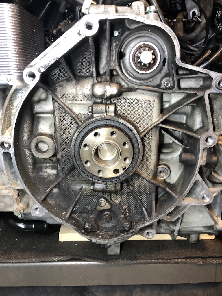
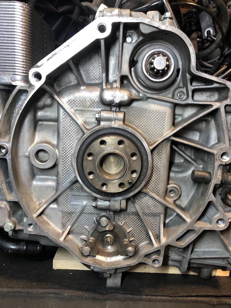
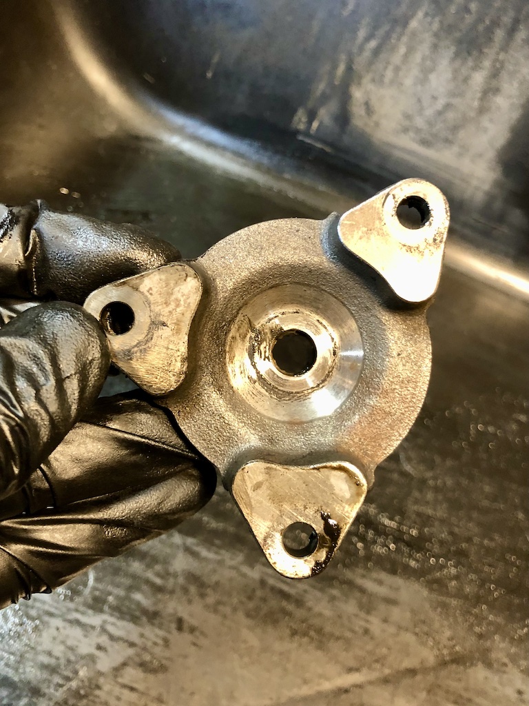
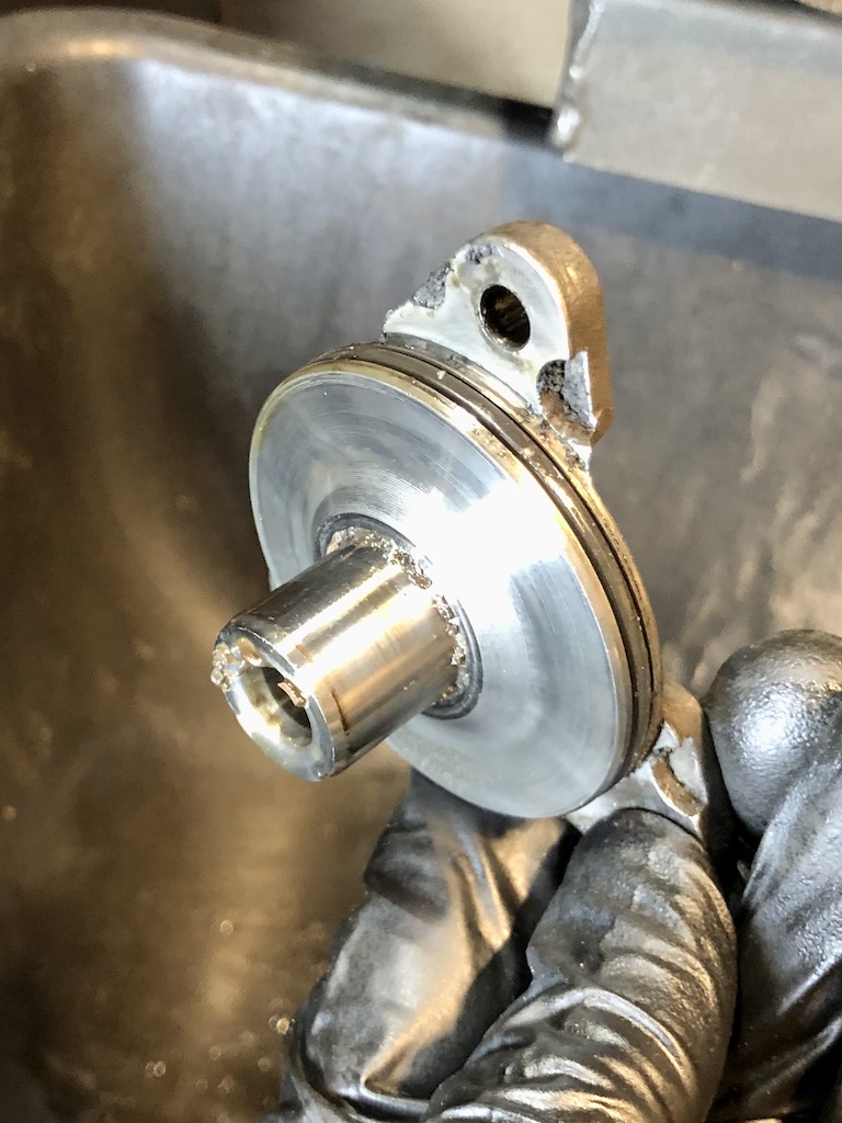
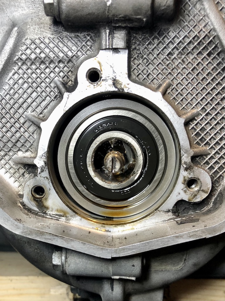
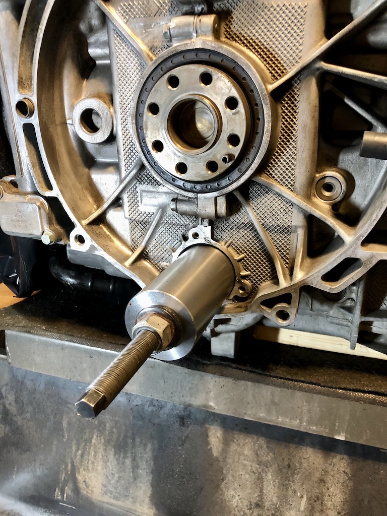
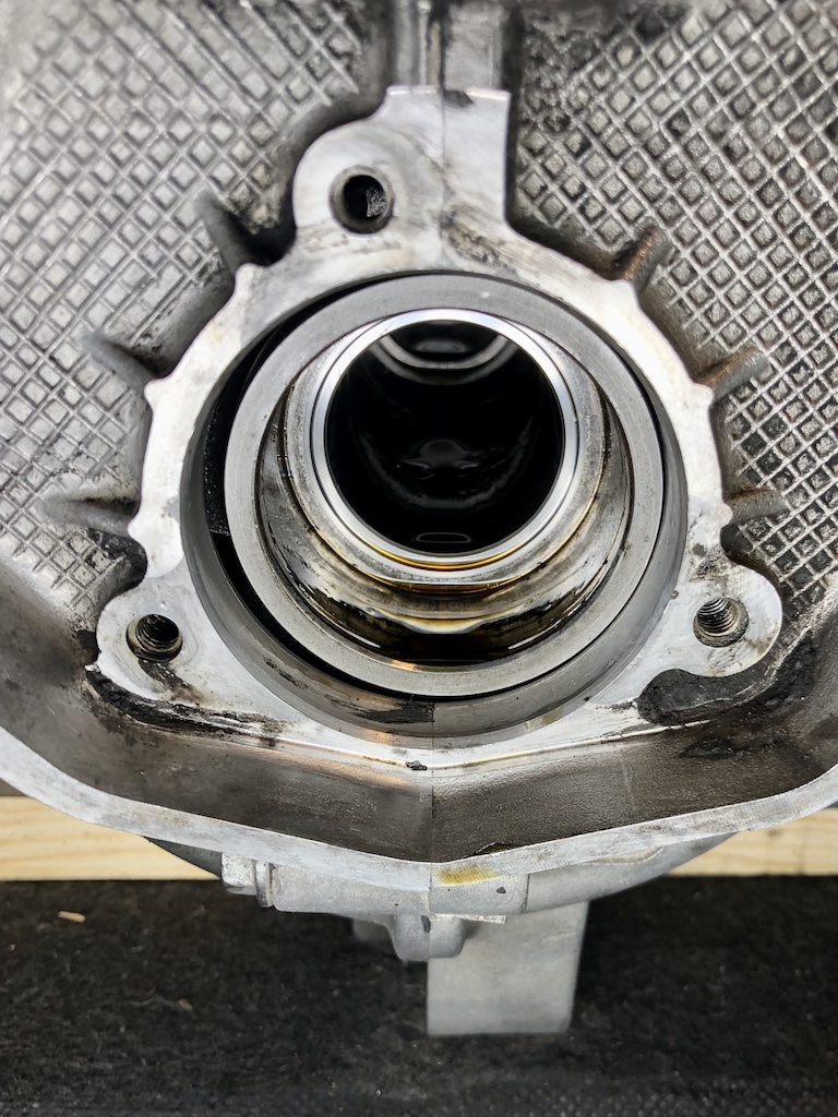
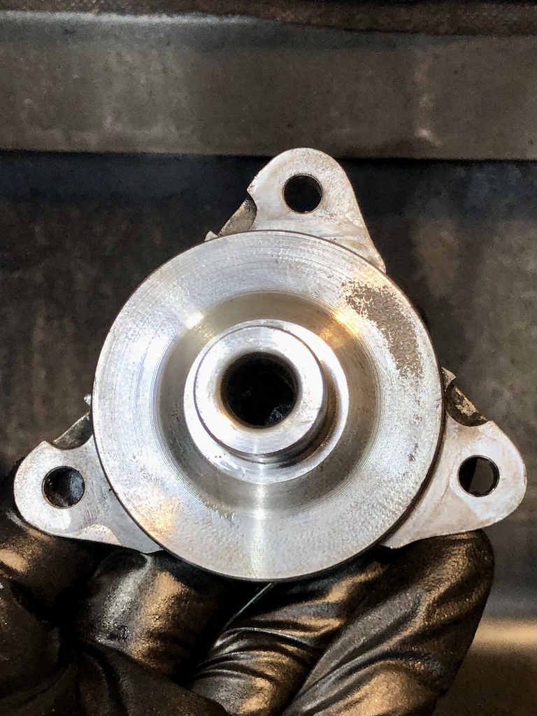
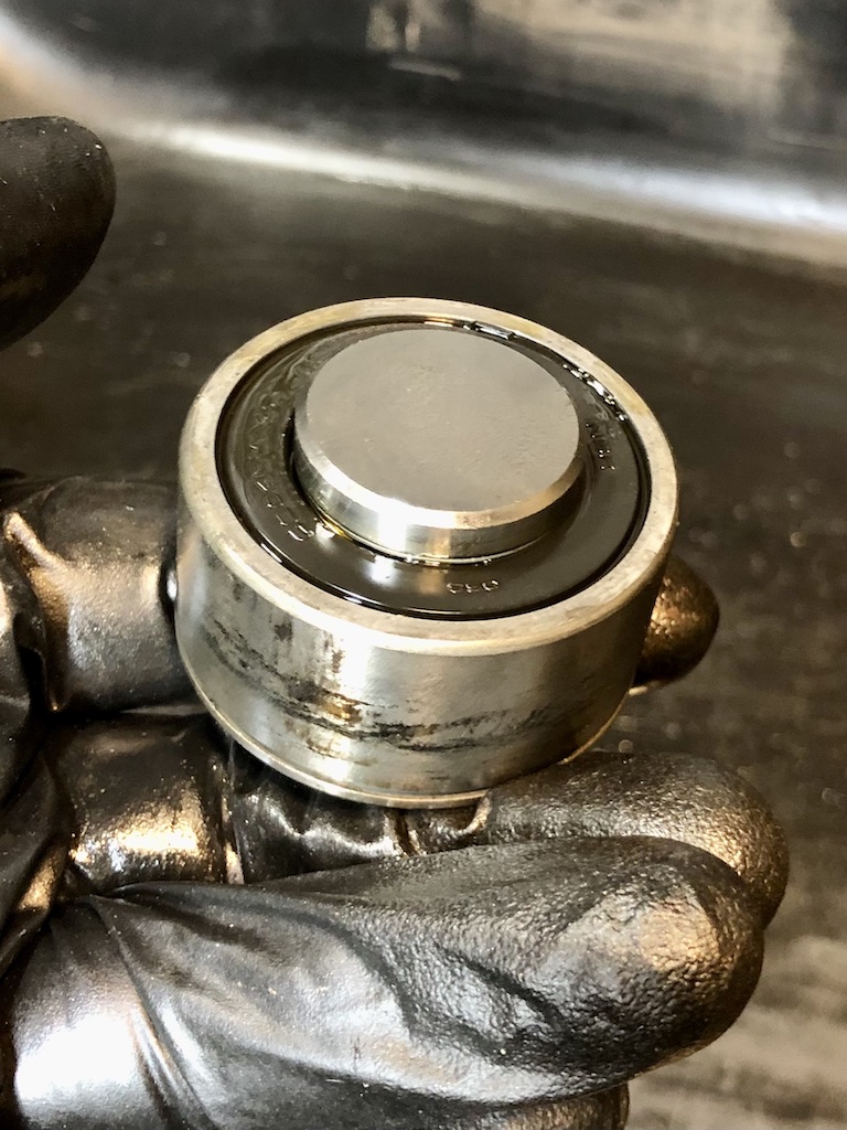
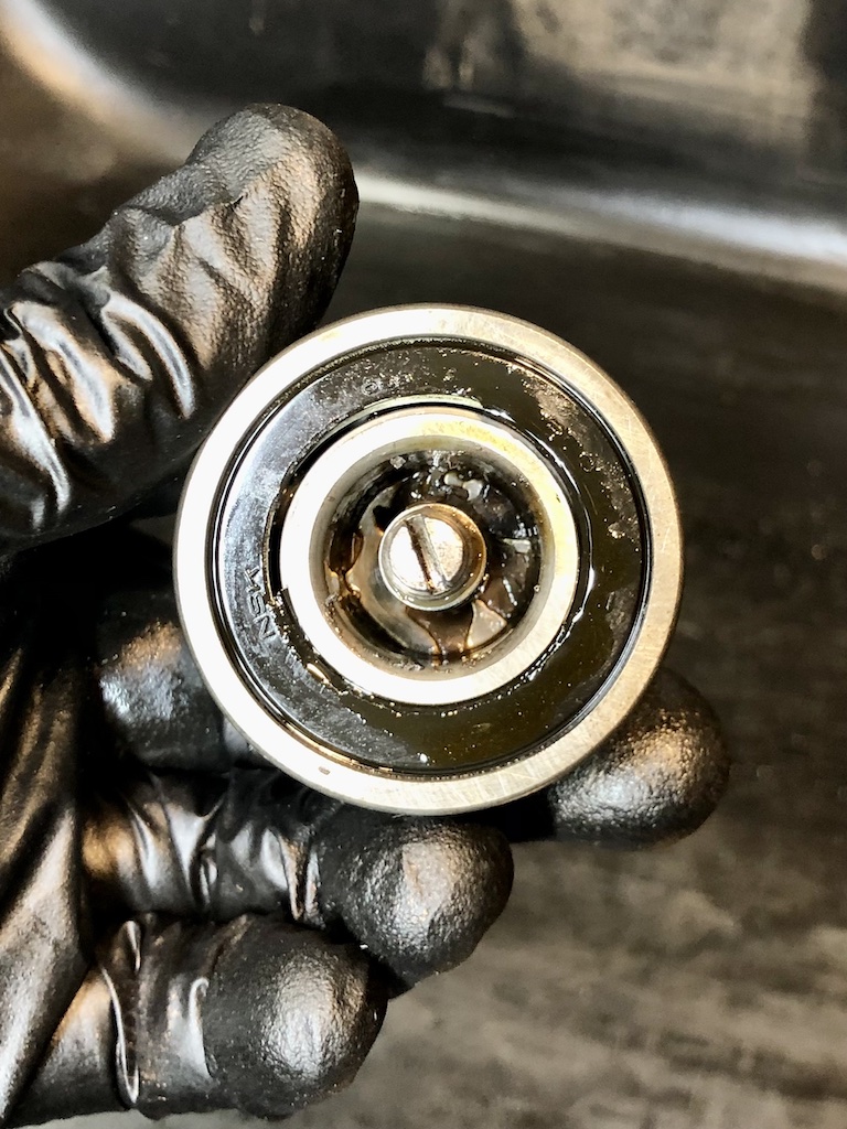
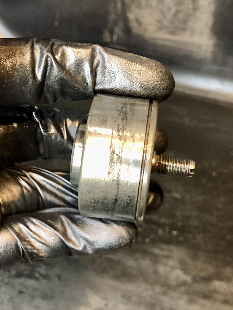
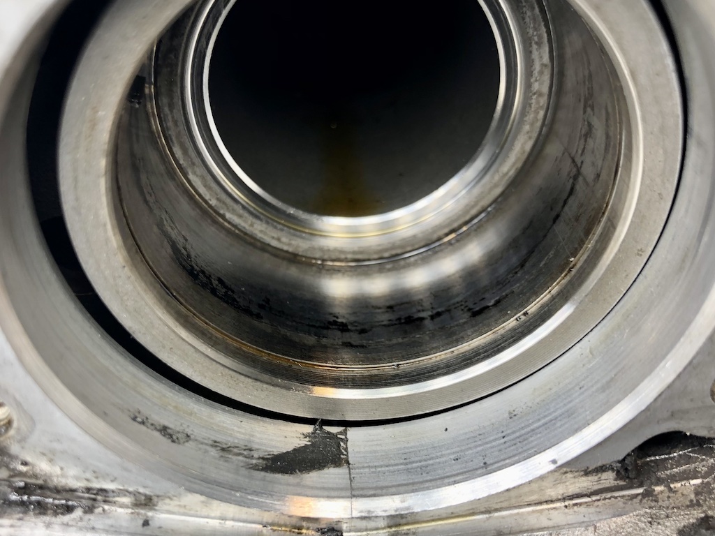
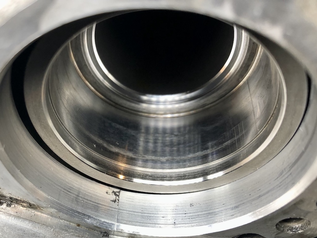
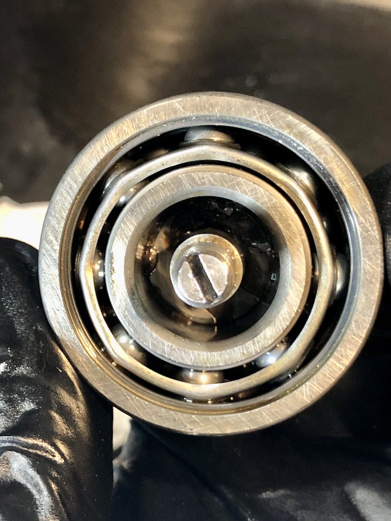
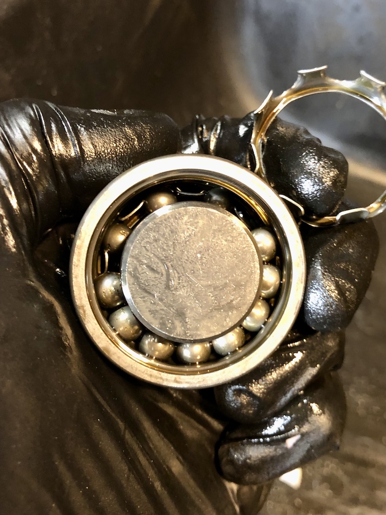
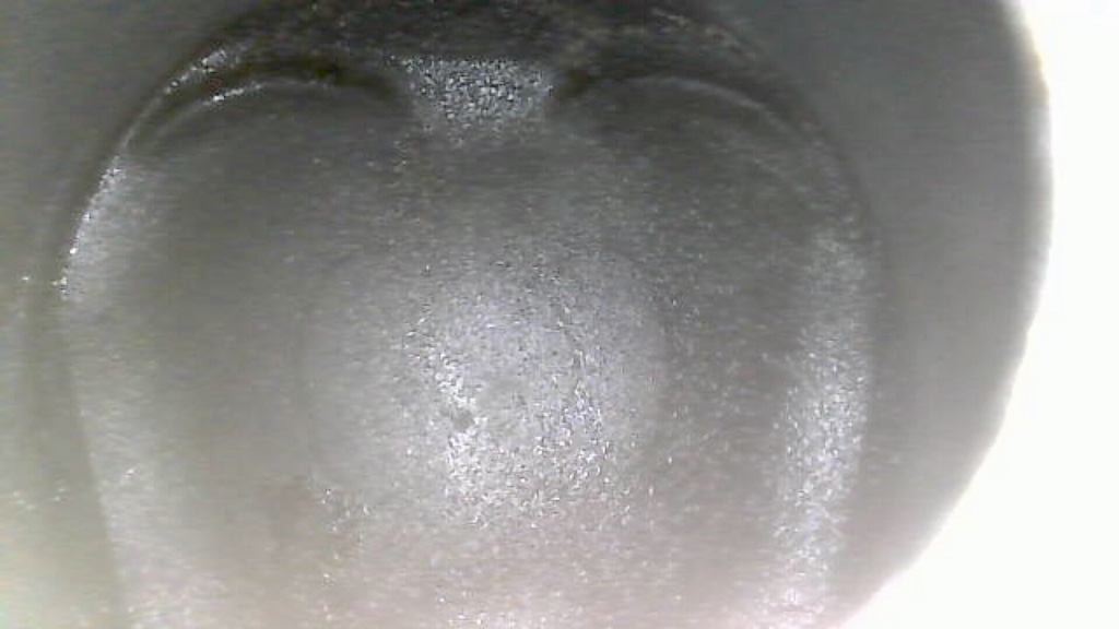
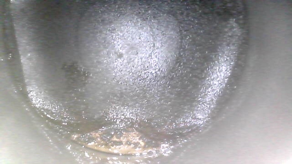
Pulled out IMSB, pics below. Everything looks like the bearing did not fail. Bearing spins, but not freely or necessarily as smoothly as it probably should. Some movement fore and aft, less so laterally. All bearings seems to be in tact, but some of the balls have loss of material, which likely explains the particulate I found inside the shaft. Curious what you think about the pitting on the inside of the flange and the black scuff marks on the out race of the bearing and inside of shaft end. It seemed to clean up nicely. Is the particulate I found normal or an indication of the bearing due for replacement?

-
Thanks JFP on recommendation. Having an exchange with Len and obvious after a few exchanges why you are recommending him. I was wondering before I keep going, if ok to do the IMS work now, my reasoning being if I discover issues with IMS, I may have to rethink what I'm doing with this engine. LN instructions call for locking cams presumably because most scenarios assume heads are in place. Do you see any issue with pulling and replacing IMS bearing with heads off if engine has been locked at TDC and chains are secured against the guides... or do I need to wait to have heads back on w/ cams, etc.
-
I attempted to spot check variation, and there appears to be some, but very difficult to confirm with springs in. Essentially, after thinking it through, I agree with you that I have to remove the heads. Even with the cams out, I'm getting air out of the exhaust, so have to resolve that. In addition to my question above regarding timing, questions below about head job... - Would you recommend I take the head to machine shop for resurfacing? - Is there anything I should do with the head before taking it to the shop? - Unless I find any obvious defects with guides, stems and springs, plan to reuse? Is there anything here that you would replace regardless? - I was thinking of lapping valves myself and checking that they properly seat and measuring for installed height, etc. Seems straightforward, but your thoughts? - Saw one of your old articles commenting on replacing head bolts. I see mixed comments and references to later 3.4 (mine is a 2000 C2) not needing to replace head bolts, especially as they don't seem to be a failure issue. I will likely be in this engine again (hopefully not to soon) to refresh the heads/rings and just wondering what I can get away with for now.
-
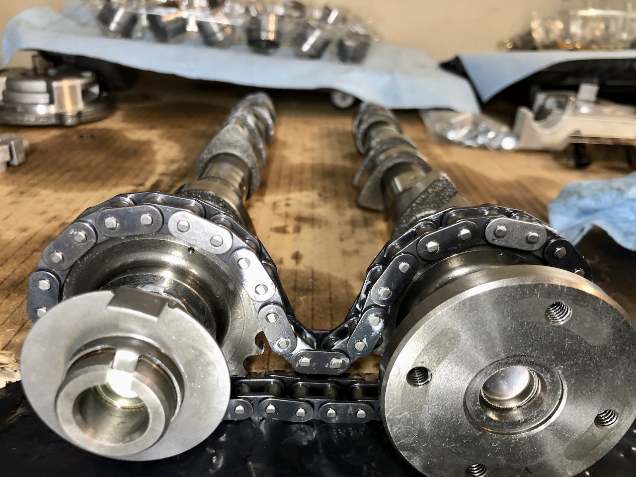
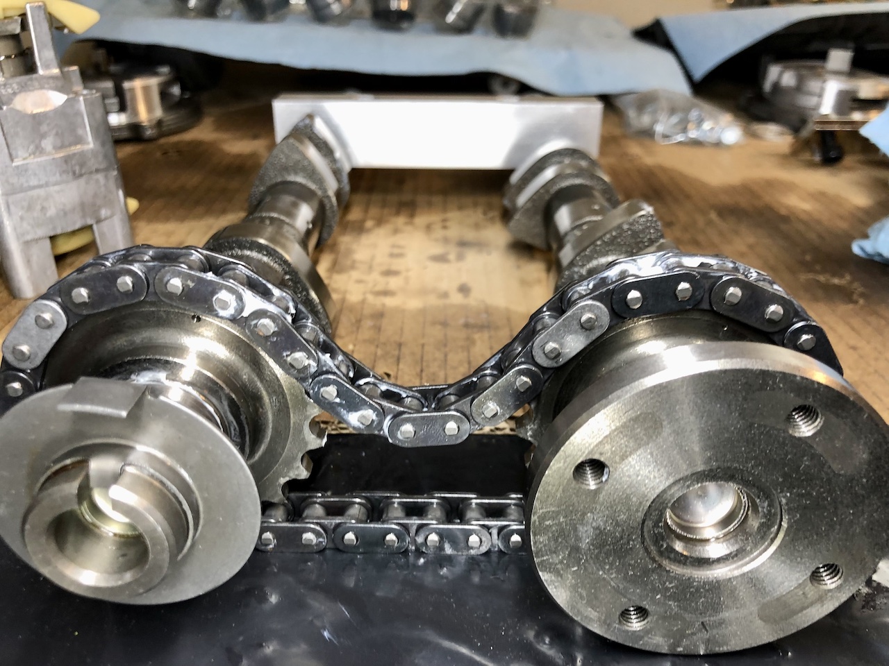
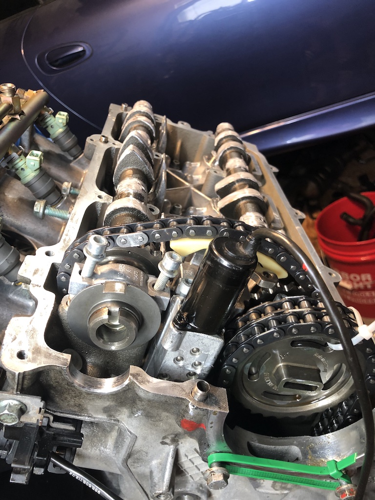
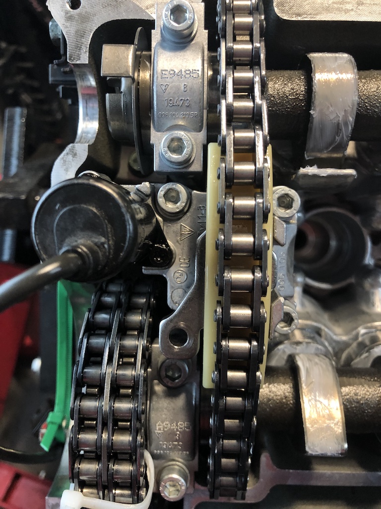
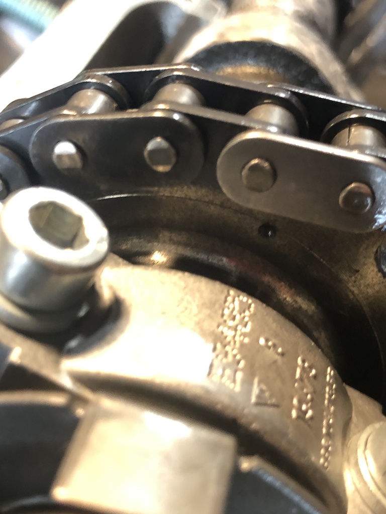
When installing... - confirmed correct cam allocation - lined up link to cam marks - assembled vario cam / cams, and checked link and mark aligned before/after install - put cam tools in place - torqued down variocam and caps - set long chain to sprocket to exhaust cam - released variocam compression tool - installed tensioner (pumped with oil) - torqued down sprocket bolts - confirmed timing marks - rotated engine 360 at TDC - confirmed cam timing with timing tool (but can't recall if I checked links / marks) Below are pictures of cams with chain in time and then after I rotate two times until cam notch is facing up (out). Again, outside of engine, confirmed cam allocation and even double checked that the new chains were exactly same as original, and that there were six links between marking links. Is it that the cams have to rotate x times before they return to the original alignment?
-
So I disassembled both banks to measure valve install height and I noticed that on both banks I was out of time (chain link to cam mark) on both banks. I assumed that they always lined up as the cams rotated back to TDC. When I took both cams out and removed the variocam to orient the chains to the cams again, I rotated by hand to see what happened and they don't line up after multiple rotations... had not read that anywhere. On the outside, both sets of cams remained in time (cam tool slotted in perfectly). Can you confirm what the behavior should be on the chains?
-
Thanks for taking a look. So I guess my next move is checking installed height. - I saw that the way to do this is with spring removed, but wouldn't measuring them in be similar or is the issue measuring from the space covered by the spring? - As I understand I'm looking for deviations from cylinder to cylinder, but is there also standard spec or range for installed height in these engines? - If by chance I see no deviations, I may still have to go in to resolve, but is there anything else I could have done in the assembly that might explain this?
-
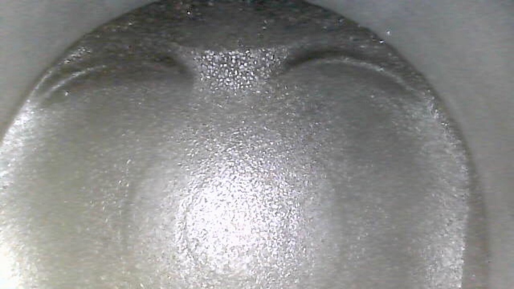
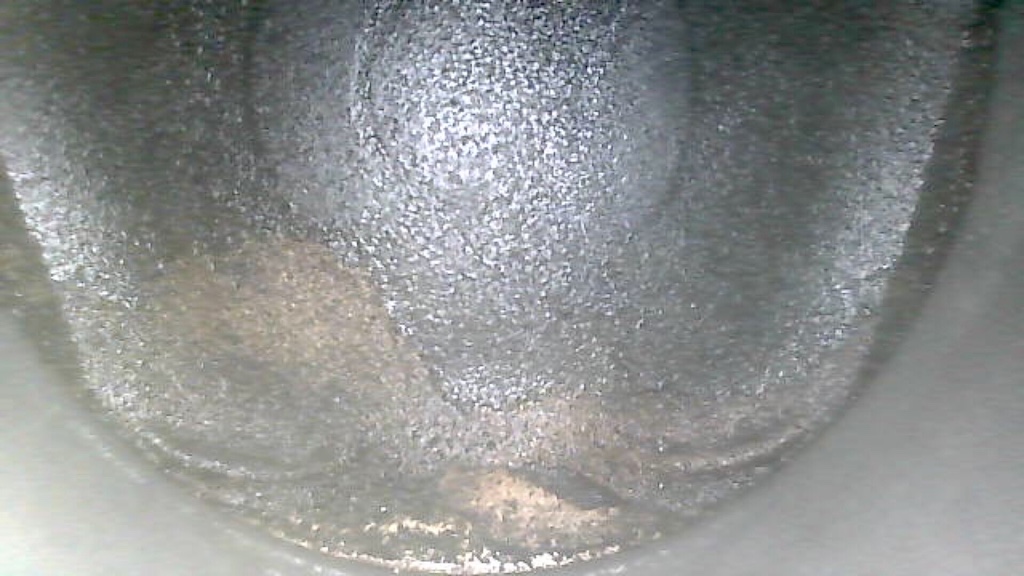
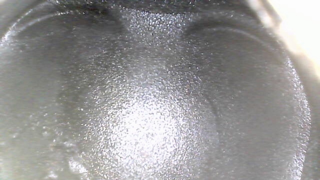
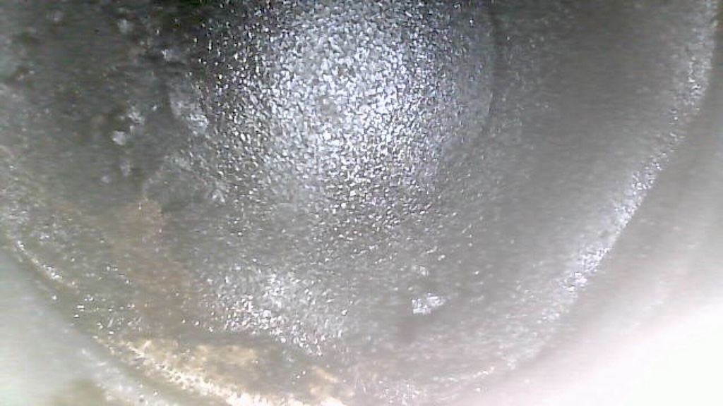
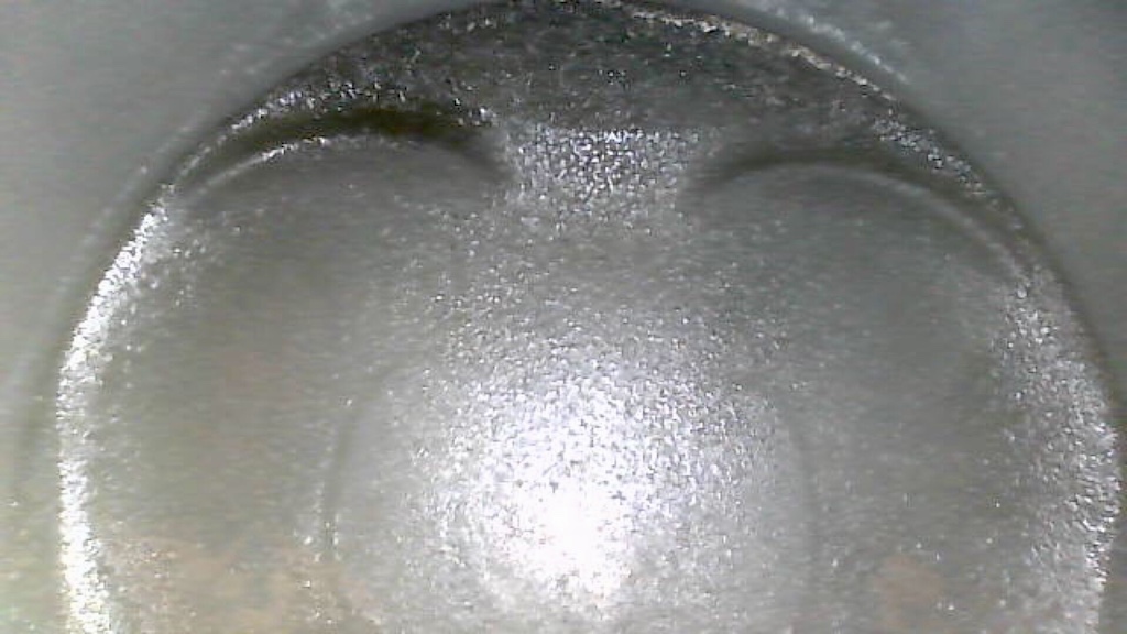
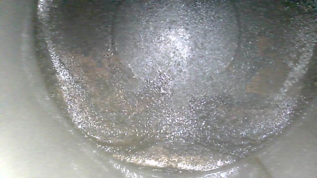
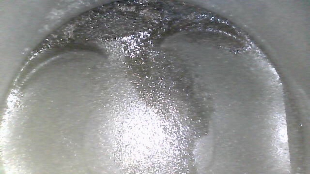
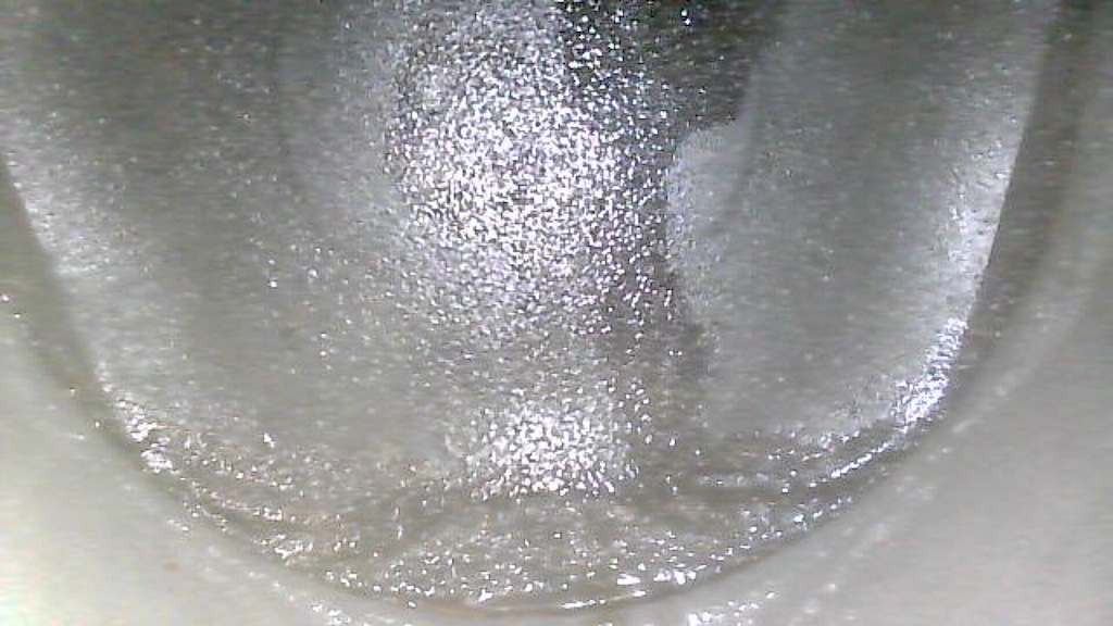
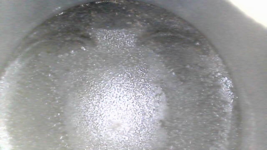
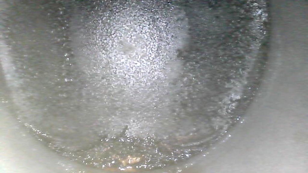
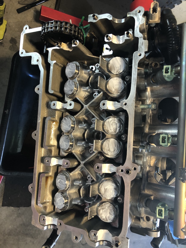
Thanks JFP. To confirm if there was piston impact, below are pictures, two for each cylinder in order from 1-6.
-
Isn't it odd though that multiple cylinders are leaking when there were no issues prior to disassembly. Assuming they're not burnt, I can see how something in the assembly process has hung them open, but again odd (although this is new to me) that multiple cylinders would be experiencing the same problem that was not pre-existing. If issue is hung open, is the only remedy taking the heads off?
-
Yes, checked twice and rotated additional 180 degrees. Same issue on bank 2. The valves are visually closed, but obviously not entirely sealed. I had checked leakage before tear down on all cylinders; no issues. to confirm, doing this with cam cover offer, with cam tools in place.
-
As a follow-up. I replaced all the lifters, set both banks timing as instructed. Confirmed respective cam notches and lobes are pointing appropriately at TDC... Everything looks good. My main concern now is if there is a simple way for me to validate that everything is operating properly. I tried to do a leak-down test (as that's what I have) but seem to get considerable air coming out of exhaust. I knew I would get more air escaping than when I did the test before disassembly because of lack of oil, etc. but not as much as I'm noticing. The only thing I can think of is that lifters may have leaked and will not "set" completely until engine is running. I just want to eliminate any potential mistakes I may have made.
-
Great... and yes, engine out. Can't imagine doing this work otherwise, at least with my abilities. And I understand need to lock TDC and cams for IMSB. To be clear about concern for potential valve damage when rotating engine by hand, I am understanding that to mean that when I set timing on one side, I need to have the cams on the other side in place, possibly with cover on as well to make sure engine components are moving in their natural state... do I have the right? (I have a 5-chain engine.)
-
Thanks. I'm seriously considering that route. Because I'm in wait mode (other parts / soaking bank 1), is it ok to open up bank 2 while bank 1 is open to do timing / refresh items, or is it best to have one side done before getting to work on the other side? I also have the water pump and oil drive / valve upgrade and just wondering about the best work sequence. I am assuming it's best to do the IMSB after I have everything timed as well. Thoughts?
-
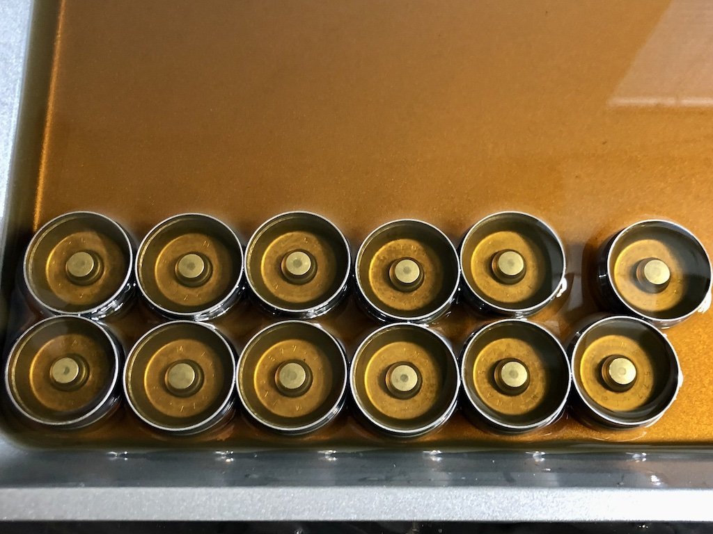
I'm doing a top-end refresh on my 2000 C2 as part of IMSB and timing correction. Looking for advice on how to evaluate / treat the lifters. Background... When I inspected the lifters, all look good cosmetically. When they came out of their cradle, they all were stiff as you would expect, except for one or two, but generally not squishy. At first, doing this for the first time, I thought that was a bad thing until reading up on it. As I understand it now, they should be stiff coming out of the engine and weep over time when outside of a pressurized environment. So when they remained "stuck" after being out for 2 weeks while I worked other items, I began to wonder if they were that way for all the wrong reasons. I worked them over a couple of days while I did other work, getting the old oil (very dirty) out of them. I gave them a hot bath in engine oil as some threads suggested to get the air out of them and to replenish with new oil. I was worried after a day that I should have left well enough alone as they were all still very pliable, so I did a repeat hot soak (forgive my novice terminology), depressing them each several times. After another 24 hours there's a huge noticeable difference. They're still not quite there yet, but maybe it's just a matter of time. The idea being if any cannot accept/retain the new oil, I'll replace them. I know that once in the car, if not damaged, they'll regain their appropriate state, but I want to make sure before they go back in that they have a likelihood of doing so. Questions... How long does it normally take for them to be soaking in oil before I can properly check them? How much play should they have / not have? If for argument sake, one or two are bad, do I need to replace the entire bank of them, all 4 associated with the respective cylinder, or just the bad one? I found the OEM INAs on eEuroparts for 16.97ea. roughly $400 for all 24, which isn't bad, but I'm trying to keep costs down on this project (without doing something stupid along the way).
-
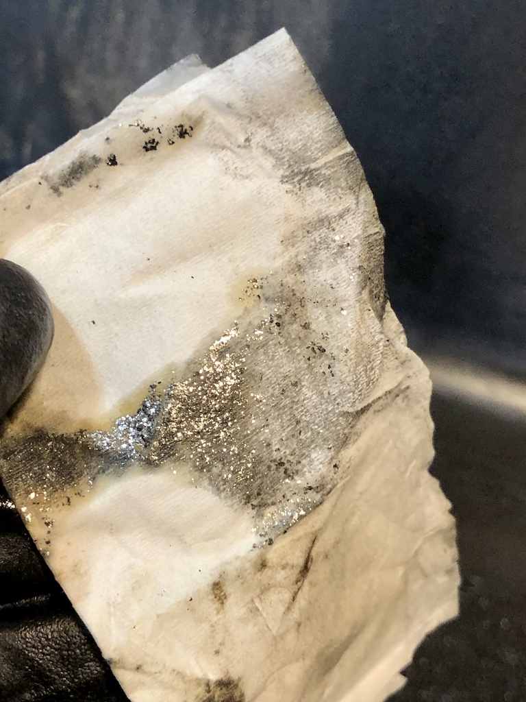
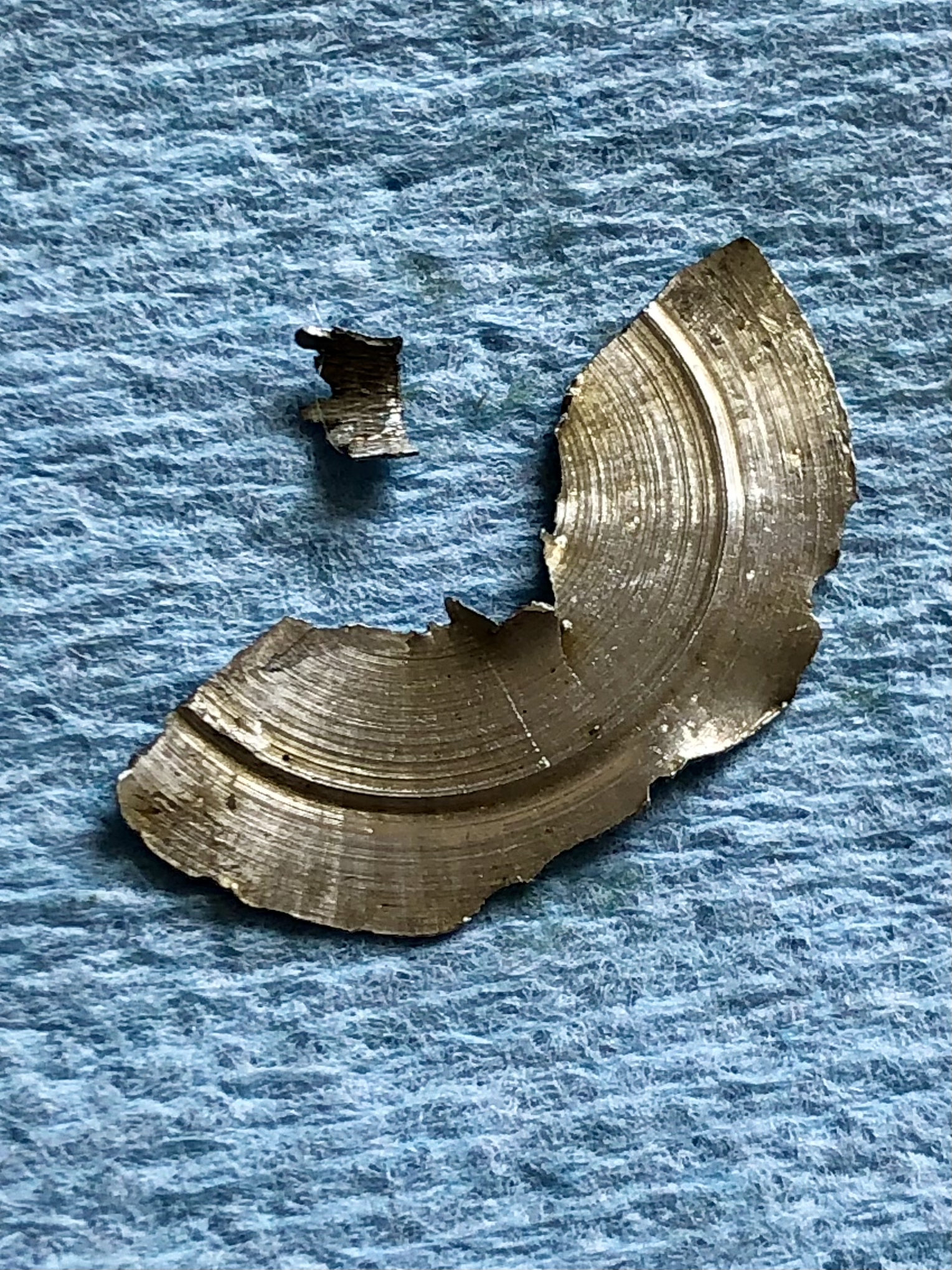
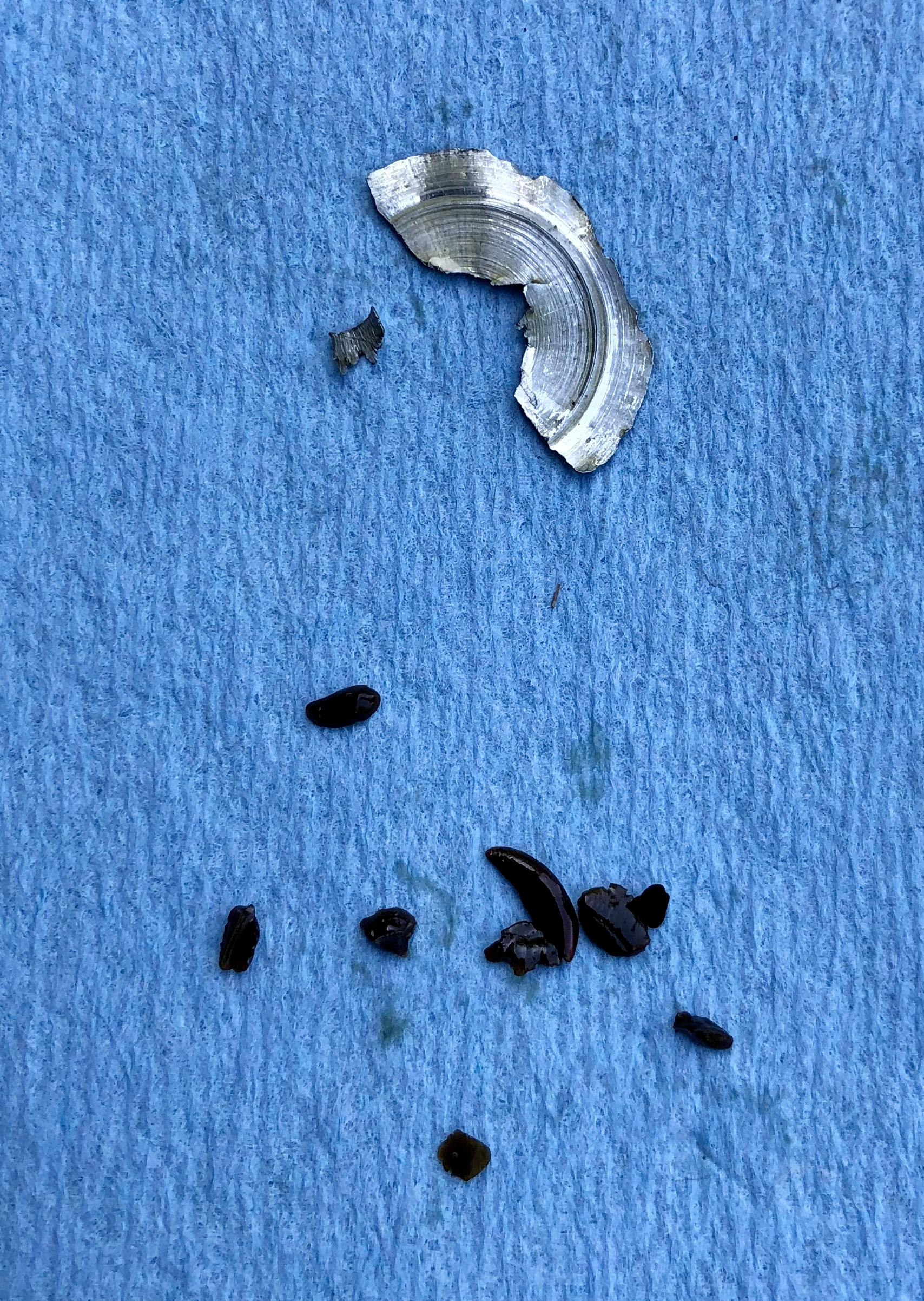
None of the bits are ferrous. The little dark ones appear plastic and likely from chain guides. The two silver ones are metallic, but non ferrous. The larger piece's diameter is slightly larger than that of a penny. The oil filter had some metallic specks but nothing extreme in size or quantity. I'm sending oil to blackstone to be evaluated. In all my research, just have not seen anything that looks like the larger piece of metal.
-
PROJECT UPDATE So finally got my project kicked off and in draining fluids, found the expected plastic timing guide bits, but also found two metal pieces, one rather large that I was not expecting. There was nothing in the filter. Found these at bottom of sump. Any thoughts what's going on?
-
Door Microswitches
hankster66 replied to Richard Hamilton's topic in DIY Articles - Carrera (996) - Common Fixes and Repairs
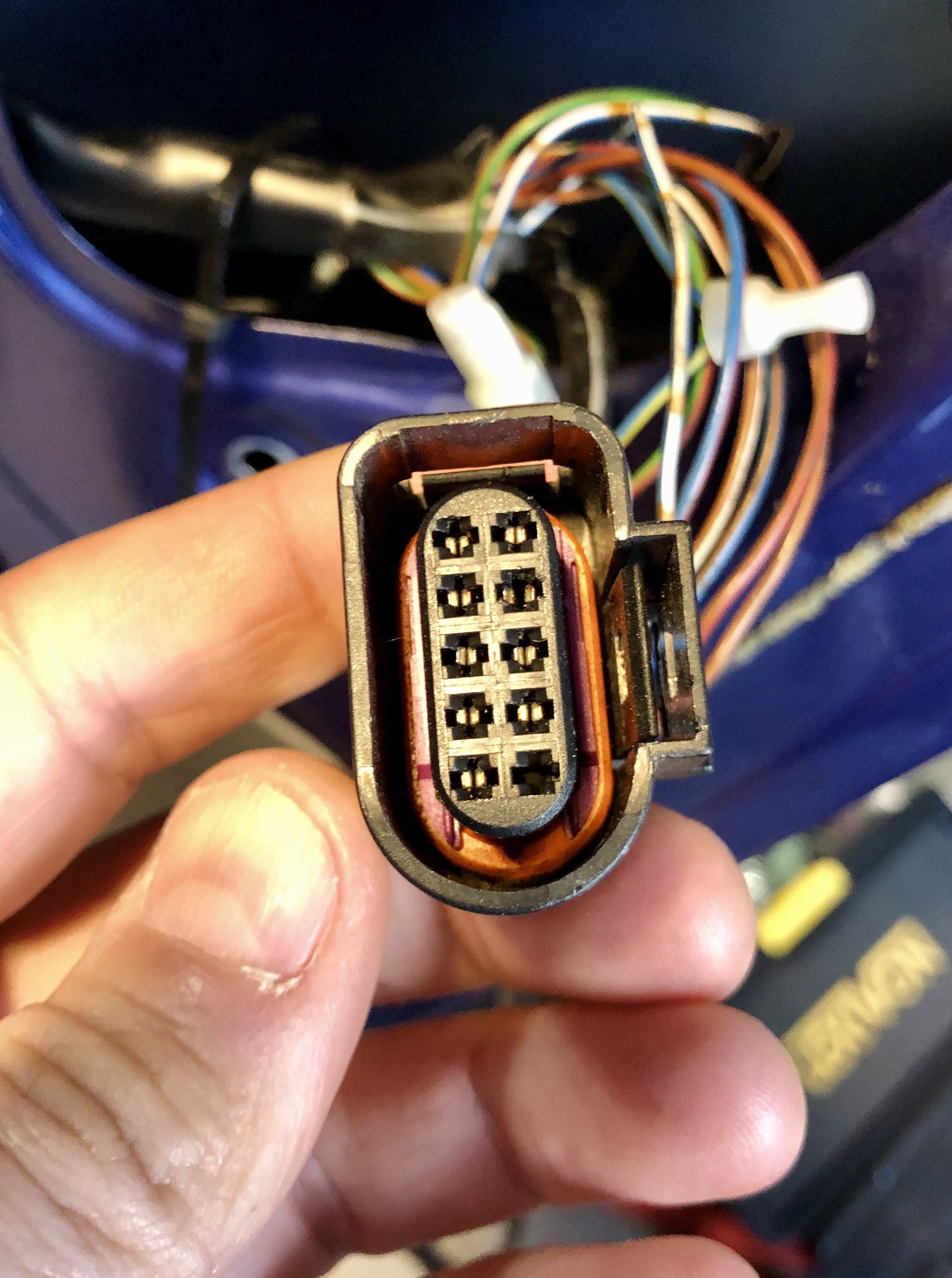
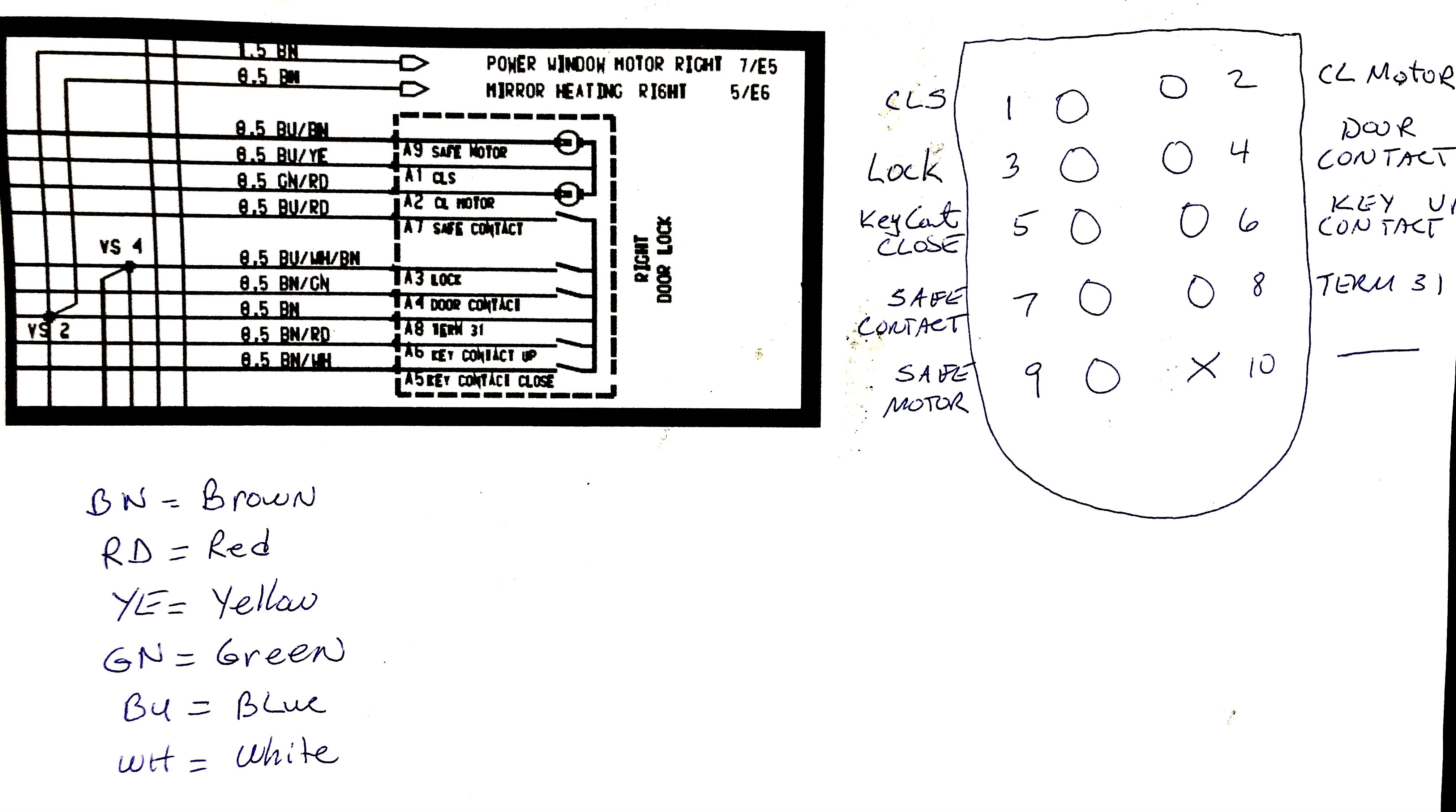
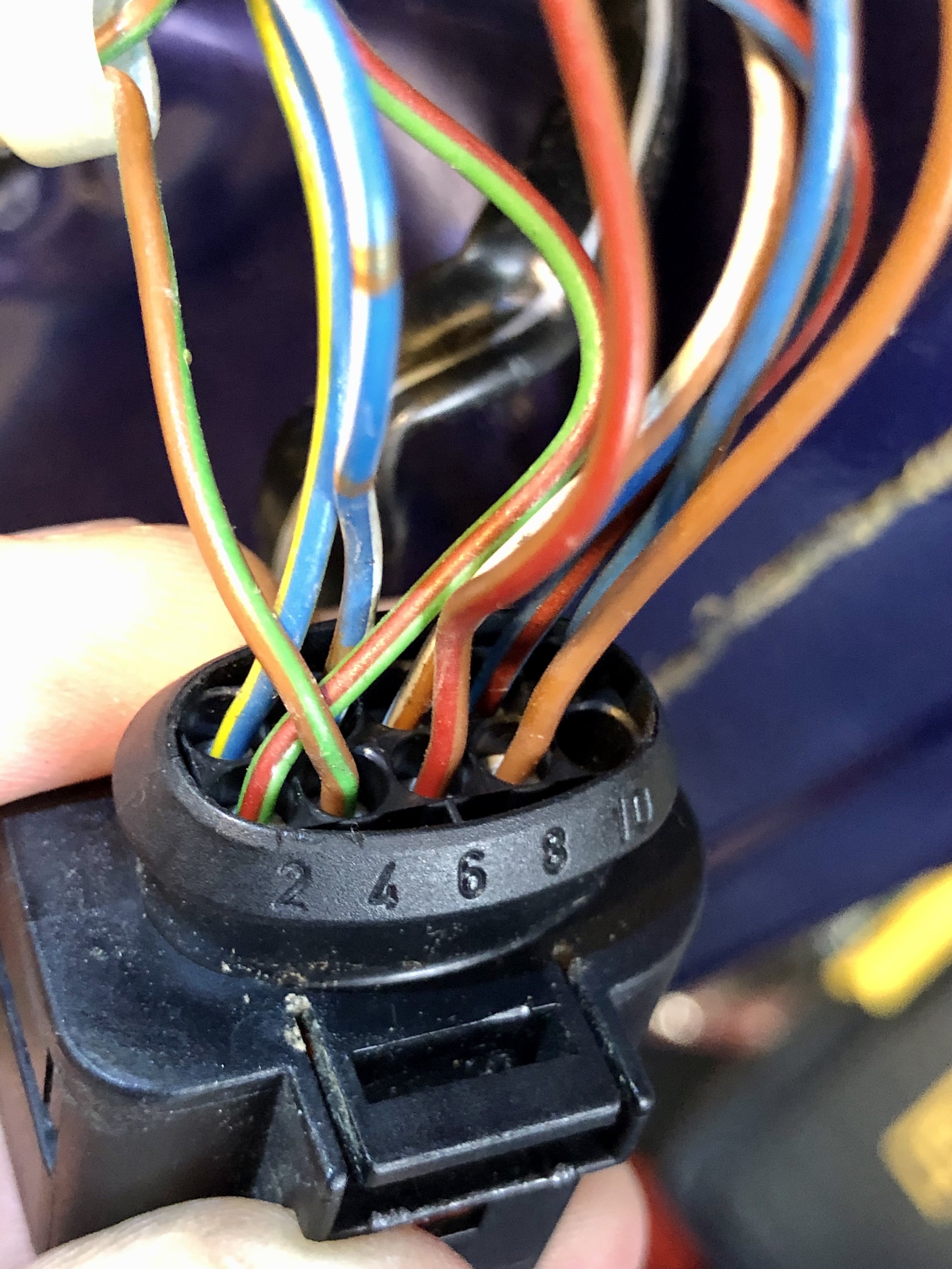
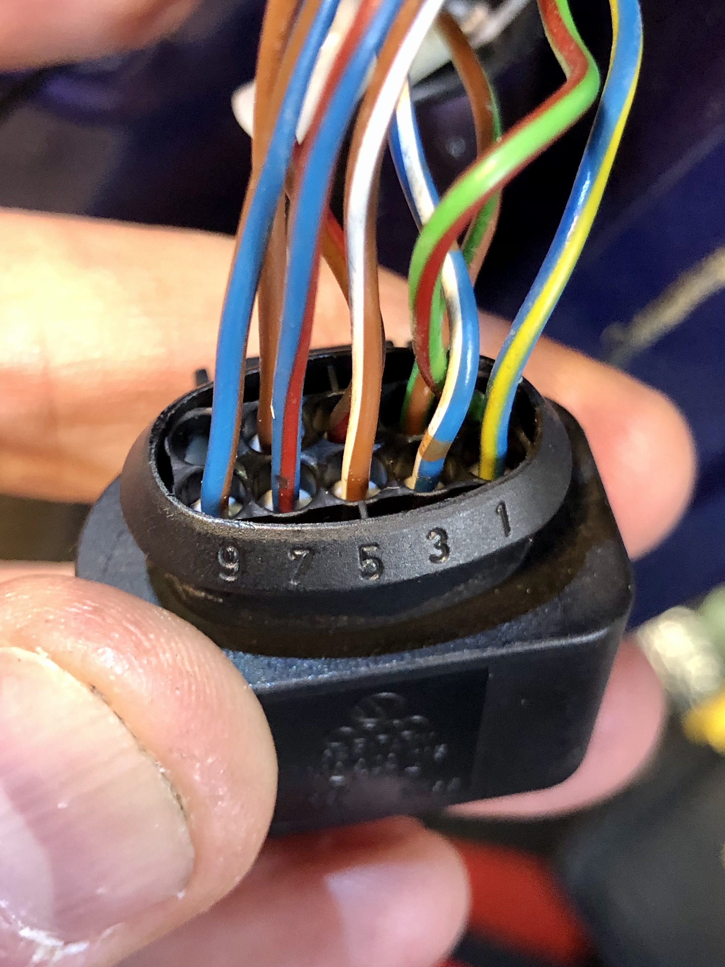
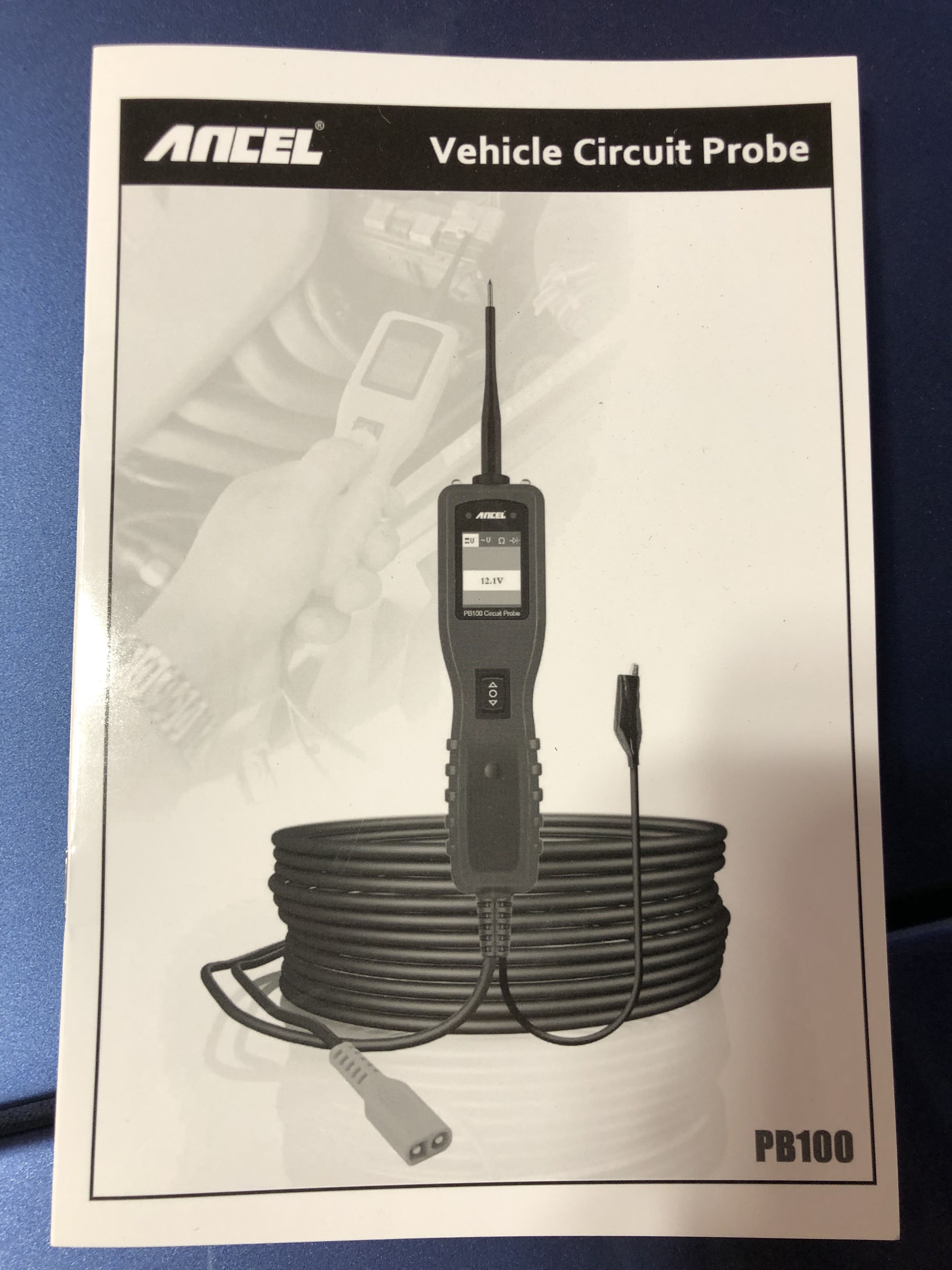
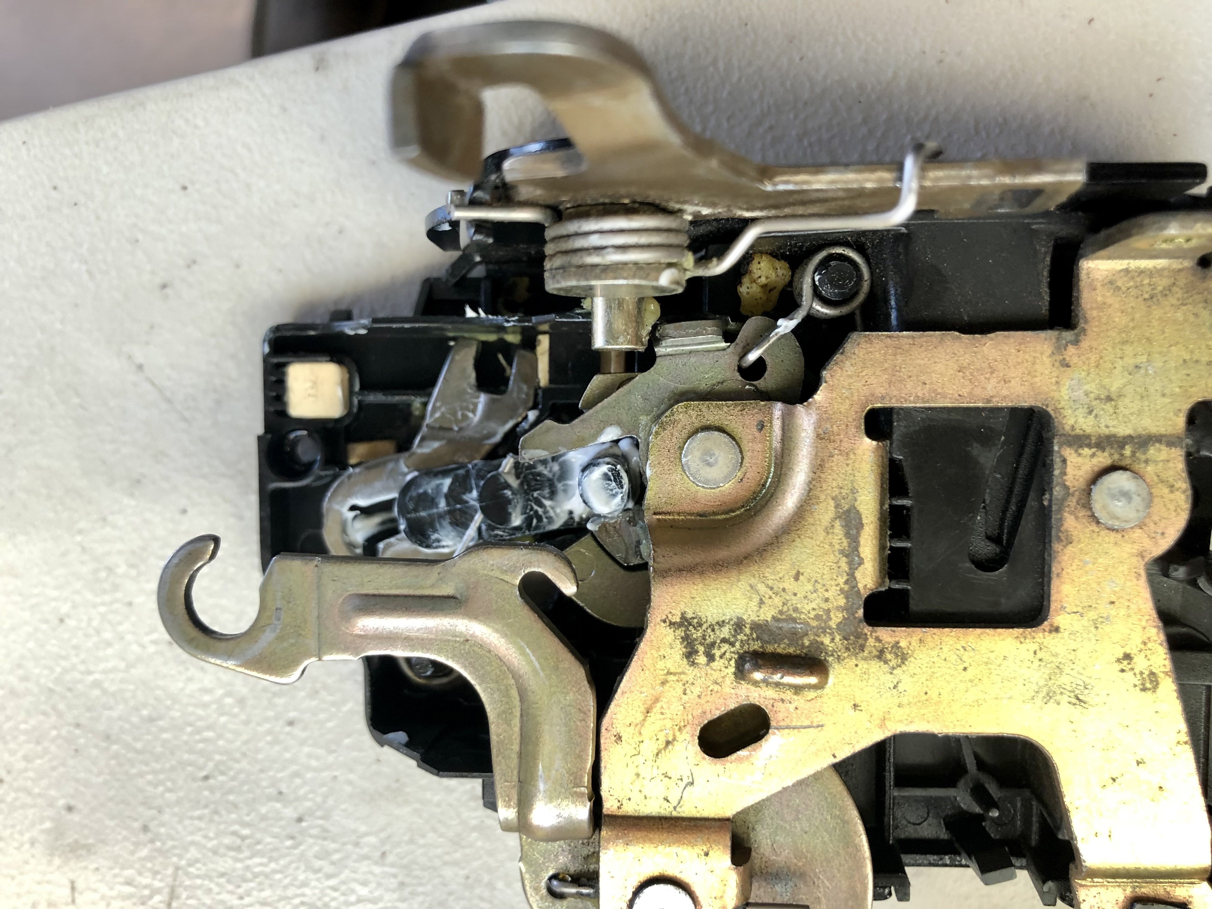
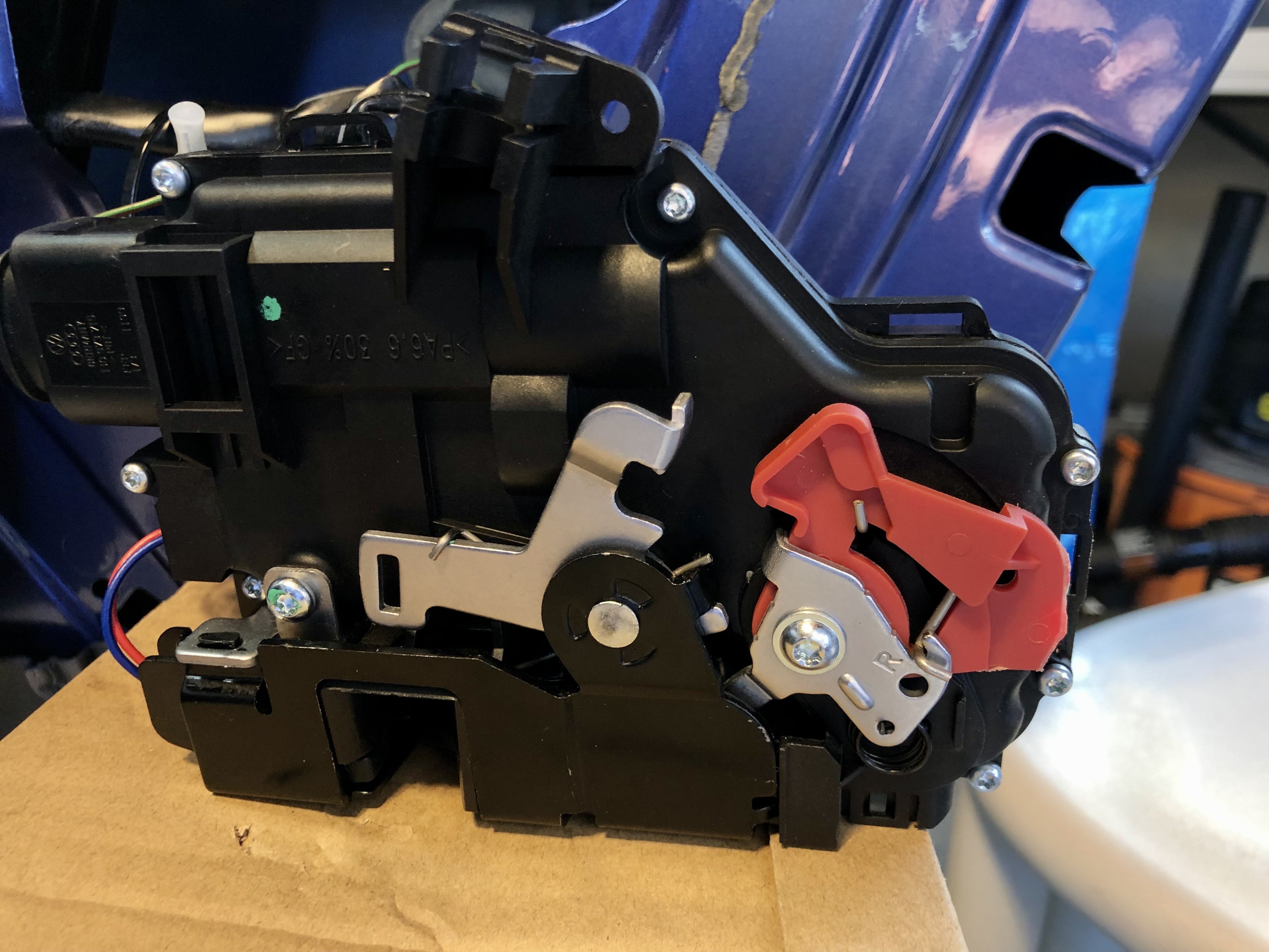
So I completed the project and will detail below, but quick recap here... Tested for ground fault (bad earth)... no issue which I suspected as window, door light, etc. were operating on passenger door. Taking Richard's diagram, I mapped out my own diagram to troubleshoot connector to locking unit was good... checked out ok. Because power was going to the unit and it would not lock/open when triggered, I new I either had a mechanical or sensor problem inside locking unit. I tried to see if there was anything obvious (mechanical) I could fix by taking it apart and reassembling, but nothing worked. Ordered alternative replacement (part) which I'll explain various options and why I decided on this approach. Job completed and for the first time since I purchased the car... no double-beeps and car locks/opens as it should. TROUBLESHOOTING ELECTRICAL As I'm not an electrician (accustomed to reading diagrams), I mapped out my own diagram in the form of the 9-pin connector so I could see what was happening with each wire to make sure something there wasn't a troubling contact or shorted wire to eliminate those before assuming it was the locking mechanism. Since this was my first project (of several to come) I researched and purchased an automotive circuit tester to test for ground (earth) and to check each of the connections on the connector. With car off, no key ignition and car door open: Connections #1,2,8,9 showed ground connection; and #4 had 12.8 v, while all others no signal. When triggering key fob, #5 and #7 would momentarily show voltage. I didn't go through the various permutations of door locked and ignition key, etc. to fully validate; with power and ground and no response from locking unit I felt that I had enough to point to the unit being the issue. I am sure there's probably a better / more methodical way to do this, but I primarily wanted to build some basic troubleshooting skills and have a better understanding of how the electronics work. There are scenarios that could involve circuit breaker and other trouble sources, but there were no indicators for me to research further. OPENING UP THE DOOR PANEL Having never opened up a door panel, I went on the search on youtube and found an excellent and highly details teardown video which I reference. I didn't run into any issues on teardown or reassembly... fairly straightforward. TROUBLESHOOTING LOCKING UNIT - MECHANICAL After gaining access to door components and eliminating source power/ground to locking unit, I researched next tier potential fixes. There were a couple of posts/videos out there on identifying and replacing specific sensors. I felt I had more of a mechanical issue going on, or could be dealing with both a mechanical and sensor issue, the latter of which I felt was beyond my capability and time investment interest. If you wish to pursue replacing/fixing sensor, I found this "Door locking mechanism rebuild" rennlist thread in the 996 Forum. Again, to advance my understanding of what I was dealing with I discovered the video below "Porsche 996 unlock door doesn't open" showing how a particular internal component can get stuck... solution was to shave down (using dremel tool) some of the material and apply lithium. When tearing my unit apart, I actually did discover I had a similar scenario. below the video is an after pic of my unit after shaving some of the material and applying lithium grease. While this appeared to solve this particular aspect, it did not ultimately solve for the lock not operating (pointing to some other mechanical issue and/or faulty sensor). The picture below is of my unit and attempted fix. In addition to greasing these related components, I did the same with other moving parts that appeared to be "sticky". While not ultimately successful in getting the lock to work, It was nice to check out the inner workings and other potential paths I could have taken. The video below is a helpful and more detailed guide of splitting and reassembling the unit. MODIFYING ALTERNATE REPLACEMENT After confirming bad locking mechanism, likely due to bad sensor, I proceeded to research replacement options. Below I list the pricing primarily from Pelican Parts so there may be different pricing available elsewhere, but just showing relative price options here for reference (specifically to right door): Genuine Porsche Replacement: $408 Pelican Parts Genuine Porsche (#9A783701503) 996 3rd Party Replacement: $150 Pelican Parts URO 996 compatible part (#8N1-837-015C) VW Alternative Part: $55 Ebay VW "alternative" part (#1TD837016A) There are number of threads advocating for Genuine Porsche replacement, which I totally respect, to a variety of other replacements. For roughly $55, I thought it was worth the gamble to "hack" a solution for a non-critical part. Obviously locking your car is critical and I certainly would not risk purchasing a component that could do more harm; I did not see any harm in a component designed for other german vehicles, other than the risk of winding back at square one... that was ok for my situation where I'm on a journey to tinker and develop knowledge with my "project car". The video below walks you through cutting the "excess plastic" (red colored part) from the VW alternative part. Another option to cutting the red, is removing it and replacing it with the piece from the original. I considered that, which requires adeptly putting back in place two sets of springs. To avoid the headache and frustrations I imagined, I decided to cut the excess plastic. If you're skilled at this kind of work and you want to preserve the option of returning the part, you might go a different route. I found this video imbedded in a step by step picture guide here. Below is a picture of my replacement unit after I trimmed the red part so as not to have any of it extend (to the right) beyond the edge of the unit. The video recommended use of a dremel tool, which I had but I did not have cutting wheel attachment. I used a combination of a utility knife to score the section I was going to cut away, and finished it with a wire cutter. I did not want to bend the plastic for fear of breaking off more than I wanted, so took it in small steps. The plastic is relative soft and not brittle, so you should not have any issues with whatever tool you have readily available. The only other adjustment required is transferring the (white) cable assembly from old to new unit. IN CLOSING 4 months into P-car ownership AND first time car tinkering, it was a pleasure to finally close out my first project. I've been working and prepping for what began as a clutch/flywheel/imsb to discovering I have to fix cam deviation, so now having to drop engine as well... much, much bigger than a door lock... but nice to have a "win" under my belt. Since new to P-car, also new to forums, which can have you second guessing everything you do... lots of noise (people with opinions), but often little objective insights (valuable information without judgment). I appreciate having discovered people like Richard Hamilton from across the pond who have in-depth knowledge, long history of helpful posts, and went out of his way to take time to respond to my newbie questions!!! I did this post to document my journey in trying to figure out how best to tackle the problem and learn along the way so that the next person could possible spend less time researching and not fall into analysis paralysis in figuring it out. My scenario is I can take my time (not a daily driver), which may not be yours, but now you have options and can choose what works best for you. Lastly, I am absolutely certain there are some things I missed and could have done, but here too I pointed them out for the next person to explore. Any other approaches I could have taken not listed above... by all means share!
-
Door Microswitches
hankster66 replied to Richard Hamilton's topic in DIY Articles - Carrera (996) - Common Fixes and Repairs
Thanks for taking the extra effort to educate! I ordered a circuit tester as I needed anyone anyway for general troubleshooting, but my hypothesis was that if windows and other things working on that side, likely not a ground fault. I'll test it anyway, but likely to proceed with replacing the locking unit, but waiting to open up the door panel and check things out before ordering anything. I saw some videos/threads that show how to tear down to fix the specific faulty mechanism/switch, but not sure I want to bother with that. The one option I'm considering to OE replacement is using the lower priced and quasi-equivalent vw door lock unit which appears to only requires a minor physical alteration... but again, want to see what's behind the door panel first. Again, thanks for all the info. -
Door Microswitches
hankster66 replied to Richard Hamilton's topic in DIY Articles - Carrera (996) - Common Fixes and Repairs
Thanks. I forgot to ask before, but when you say "bad earth"... is that a bad ground in the UK? Learn something every day. -
Door Microswitches
hankster66 replied to Richard Hamilton's topic in DIY Articles - Carrera (996) - Common Fixes and Repairs
...one additional observation regarding door locking sounds from outside the car... - On the driver side, I can hear and feel the mechanism trying to lock at the door handle area; - On the passenger side, unlike the driver side there are no sounds/vibrations coming from the door; instead I hear and feel switching immediately before the gas cap area. Again, totally new to P-cars and their workings, so just sharing in case this gives additional clues. -
Door Microswitches
hankster66 replied to Richard Hamilton's topic in DIY Articles - Carrera (996) - Common Fixes and Repairs
It doesn't show signals, but does provide actuations to test systems... - First correction to previous is that the right door does attempt to lock... I could only feel/hear it from outside the car; unlike the passenger side where it is obvious from inside the car, it's not obvious on the passenger from inside the car. - After clearing codes, and actuating door locks w/ durametric, does the same thing as before, but instead of giving me "60" fault code, it gives me two others: - 58: "Tank servo motor not energized despite relay activation"; this fault showed repeatedly after each actuation. - 47: "Control locking synchronization"; I realized that when I did the first actuation, I still had the driver door open; This showed up "red" when open and then "yellow" when closed.