Welcome to RennTech.org Community, Guest
There are many great features available to you once you register at RennTech.org
You are free to view posts here, but you must log in to reply to existing posts, or to start your own new topic. Like most online communities, there are costs involved to maintain a site like this - so we encourage our members to donate. All donations go to the costs operating and maintaining this site. We prefer that guests take part in our community and we offer a lot in return to those willing to join our corner of the Porsche world. This site is 99 percent member supported (less than 1 percent comes from advertising) - so please consider an annual donation to keep this site running.
Here are some of the features available - once you register at RennTech.org
- View Classified Ads
- DIY Tutorials
- Porsche TSB Listings (limited)
- VIN Decoder
- Special Offers
-
OBD II P-Codes - Paint Codes
- Registry
- Videos System
- View Reviews
- and get rid of this welcome message
It takes just a few minutes to register, and it's FREE
Contributing Members also get these additional benefits:
(you become a Contributing Member by donating money to the operation of this site)
- No ads - advertisements are removed
- Access the Contributors Only Forum
- Contributing Members Only Downloads
- Send attachments with PMs
- All image/file storage limits are substantially increased for all Contributing Members
- Option Codes Lookup
- VIN Option Lookups (limited)


fedmax
-
Posts
105 -
Joined
-
Last visited
Content Type
Profiles
Events
Forums
External Paint Colors
Downloads
Tutorials
Links Directory
Collections
Store
Posts posted by fedmax
-
-
Ok found a topic with the same problem: http://www.renntech.org/forums/topic/39768-glove-compartment-light/
-
Does anyone have instructions to do so that are a bit more specific? Where does the arm go`?
Thanks
Ronny
-
Does anyone know how the glove box sensor open/close works? I've worked at the glove box and a little metal bracket came off - I just don't know from where. Since then the car honks when I lock the doors.
Thanks
Ronny
-
"Follow the instructions to alter the wiring to stop the "check spoiler" light from lighting on the dash"
What is involved to do that? At the moment my rear wing hydraulics do not work and I'd like to get rid of the warning...
Thanks
Ronny
-
I have he same issue, driver side ram leaks. We added the 5ml of oil. It went ok for 2 days and then did not retract anymore. Apparently Porsche upgraded/redesigned the system since it was first built and recommends to replace the whole system. Another Porsche mechanic confirmed that statement. The system is easy to exchange (DIY job), the issue is that the set costs 1200 EUR :(.
-
You need to wait much longer before measuring the drain, and you need to do it with the car locked. Use a screwdriver to latch the front lid, so you can leave it open while you do the test.
Thanks Richard - very good list. But still my question: with all these fuses pulled (relating to all these consumtions listed in the document) what is still draining the battery i.e. which parts are not controlled in that fuse box?
-
Are you testing it with the central locking system activated?
It was deactivated I tested the car with open doors but wouldn't that be offline anyway after I pulled the fuse C3 for central locking?
-
Thanks JFP, I know the car quite well because I took a lot of it apart the last two years. All aftermarket stuff I did myself and that is wired to the fuse box, so...I have the work ahead that I don't want at the moment :-( So bring it to the shop most likely.
-
I have an interesting battery drain. I noticed that when I leave my car stationary for two weeks, it's enough to drain the battery. I Installed a CTEK Battery health indicator and noticed that it's rarely ever green.

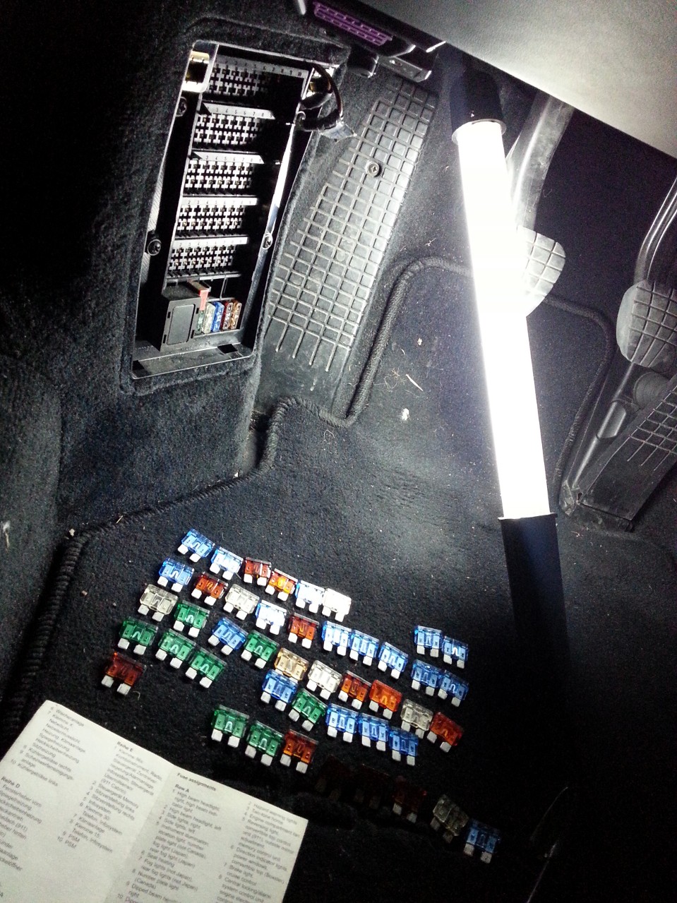
For those of you interested: the Ctek Health Indicator uses 2 mA.So today I started my investigation with a multimeter. I pulled all lamps (trunk, glove box, left and right door and made sure no other lights are on and waited till the speedo was off.
B1 pulled 167mA (Cluster Tiptronic, Diganosis and Power Top)
C3 pulled 123mA (CU Alarm System, Central Locking, Power Window)
D1 pulled 103mA (Power Window)
D8 pulled ended at 100mA (Radiator Fan 2)
So even after all fuses pulled I have still double the standby current left that it should have. At this point I have no idea where to look for as I have no accessory installed that are not going through the fuse box. The different accessories I have all end up in one fuse that I take power from (seat fuse).
Do you guys have any idea what I could try next?
Thanks
Ronny
-
sorry to hear that you have that issue. Mine went away after some time - as if the rollar had to run-in...no more sound.
-
Some of you may remember this from last year, a quick statistical 996TT review. My smart phone app hasn't changed since, nor my love for statistics.
2012 was a very good year, service and maintenance cost were about half of that in 2011, mainly due to (almost) no repairs in 2012. Repairs in 2012 included the following:
- Wishbone replaced rear right
- Light switch replaced
- Exhaust oxygen sensor replaced
- Clutch pressure accumulator replaced
What needs to be done but I just didn't get around to it this year:
- Oil pressure sensor needs to be replaced. Sometimes it drops to 0 and a warning comes on that it is broken. I found in a German board PFF that when you replace it you may also replace the seal below the oil filter housing because that should be the reason for the same oil leak I also have on my turbo. Here is the link to the forum and the picture:
- Second is the bigger problem, my rear spoiler stopped retracting and I discovered a very small leak. As a workaround I pulled the responsible fuse so that it does not come up.
Year 2012 Statistics, all the numbers:
- 22'236 km covered (13817 mls)
- 2780 liters of fuel burned (735.5 gallons)
- Avg of 12.4 liters per 100km (18.97 mpg US)
- Peak at 26.43 liters per 100km (8.9 mpg US)
- Low mark at 10.0 liters per 100km (23.52 mpg US)
- In this time I added 3 liters of oil
Top tip key learning of 2012:
Never ever use Falken 452 on a 996 Turbo if you go beyond 200km/h. I found in some strange car board that it works really well on the 996TT, well it doesn't. It's a good tyre for cruising and country roads but no high speeds on the autobahn nor on the race track. At 250km/h it gets really uncomfortable, at 270km/h I had to stop. On Pirelli tyres in 2011 I could have gone beyond 310km/h if that bend did not come up (GPS, not speedo). And that in a completely stable car that gives you a lot of confidence. Small difference in tyres...
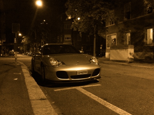
Unfortunately not so nice pictures in 2012, I had other stuff on my mind:
150'000km reached in March 2012 (Pierre would say it's almost run in)
Category every day car - DIY shopping
Still gives me a smile on my face with its beautiful shape.
Best fuel station ever I found in Lucerne: Yes you stand on a lane while you fill up...crazy.
Dirty and ready for skiing!
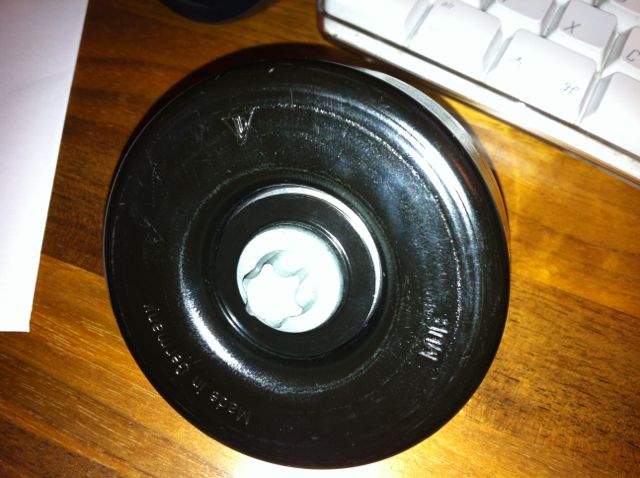
Found this little guy in the Porsche Museum in Stuttgart. No scratch so probably not used.
Happy new year to everyone and I wish you a good start into 2013!
Ronny
-
 2
2
-
-
Welcome to the club and year end greetings to Canada!
Ronny
-
Purge Valve Replacement - 03-06 Cayenne TT
I did this one a little while ago, but never had time to get these organized into a tutorial for others. Here it is. Comments are in each pic, for each step to do. Each picture is numbered in the order to be done. Hope this will help you make the replacement easier (especially if you are new to doing such work).
-
Author
-
Category
-
Submitted10/02/2012 12:55 PM
-
Updated11/11/2017 07:34 PM
-
-
Can there be any faults with mounting that tensioning roller? Maybe tighten it too much? When the engine is warm the stupid thing makes the same noise again :-( Or material defect?
-
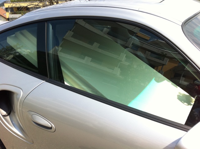
Recently my rear bumper got painted. One part that was heavily impacted from stone chips was the rear wheel arch as on the pictures below. As a have wheel spacers for the look there are many stones flying off at the painted piece.
As I couldn't find a stone chip foil for that area I did one myself. The result you can see below and even print and use as a model (PNG paper format is European A4).
-
Finally did the job last weekend, here is the DIY with pictures: http://porsche996turboblog.blogspot.ch/2012/07/issue-screech-noise-in-engine.html
-
Accumulator exchanged, everyting back to normal!
-
With only 400'000km, mine is barely broken in... :cheers:
Nice :)
-
I finally got round to replacing the roller and as Fedmax posted, the bolt does indeed hit the engine carrier. I was about to start removing the exhaust to get at the engine carrier bolts and engine mounts when the idea of a long block of wood as a lever against the engine block moved the engine carrier enough to remove the bolt and fit the new roller. Hope this helps anyone intending to tackle the job.
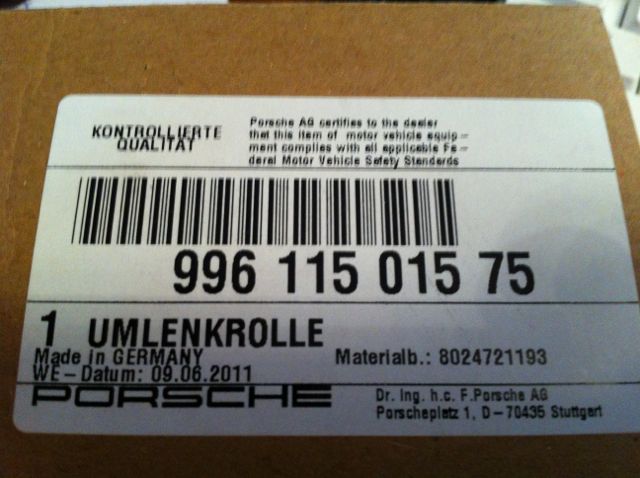
Thanks for the insight and good to know that it works. One thing that stopped me from trying was the new deflection roller has a torx rather than a normal wench screw. Was that the same in your case? Did you just use the old screw? Here are the pictures:
-
Thanks Loren, I hope its just the accumulator, I had the operating cylinder replaced about 20k mls ago.
-
Hi all
It's been some time since I had a strange issue, but one came up this week: After driving off I noticed something like vibrations when I pressed the clutch pedal. The clutch worked fine, opened and closed but a little later same drive the feel or let's say the amound of power necessary to press the clutch varied each time I pressed it. Sometimes with vibrations, sometimes without. I drove the car a few times since, the clutch works but the feeling is a different one almost every time. It feels normal from time to time for a few pressures but then again goes harder and I'm 90% sure the point where the clutch engages also varies a bit.
Remote diagnoisis anyone? Hope it's not a part failure...had enough of those ;-)
Thanks
Ronny
-
I did it last weekend, here are the instructions including pictures:
http://porsche996turboblog.blogspot.com/2012/04/solisto-iphone-mp3-interior.html
Solisto iPhone MP3 Interior Installation
Two years back or so I did a very easy installation of the Solisto device in exchange for the CD Changer in the trunk. Plug and Play. The downside is you cannot attach another device while driving or reboot it when it crashes.
The TomTom Navigation in conjunction with Spotify (or normal MP3 on the device) works really great. Music is turned down automatically when the TomTom lady has to say something, even on/off of the Radio pauses Spotify. Long story short I had to install the Solisto directly at the PCM unit.
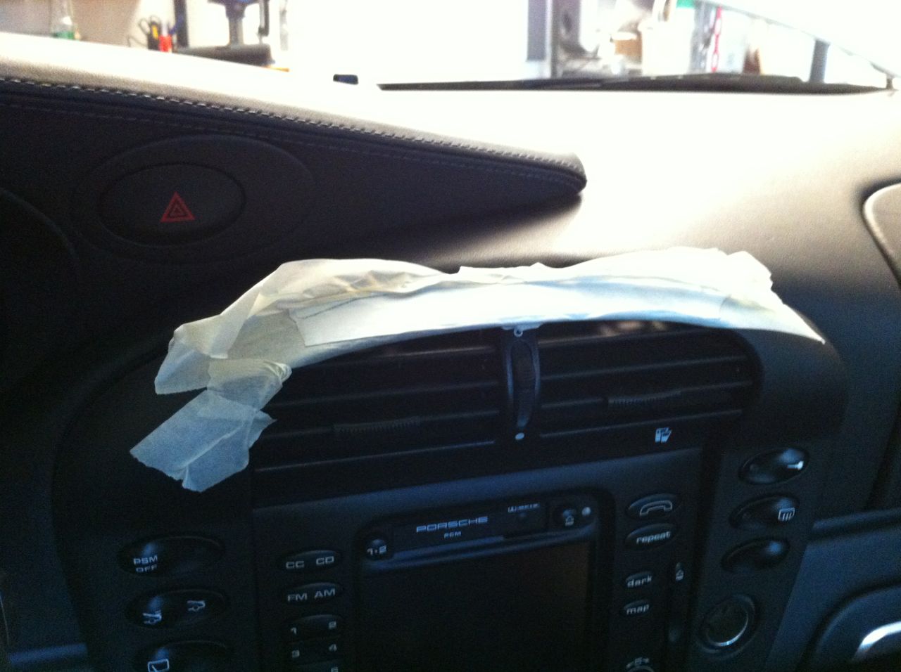
1. The toughest part is to get the cover around the PCM off. It is attached with a few hooks. Without tools I read in many forums to push down and pull forward. Depending on the car this might work. I think in my case the cover has never been off so with simple push and pulling it didn't work. To get more grip onto the top part I applied painter tape (to not damage the leather) and on top of it double sided tape. With all fingers on the tape I could pull the cover back, get a grip underneath and carefully pull the cover away.
Tip: apply painter tape to the whole cover so that you don't get any scratches in follow-on work.
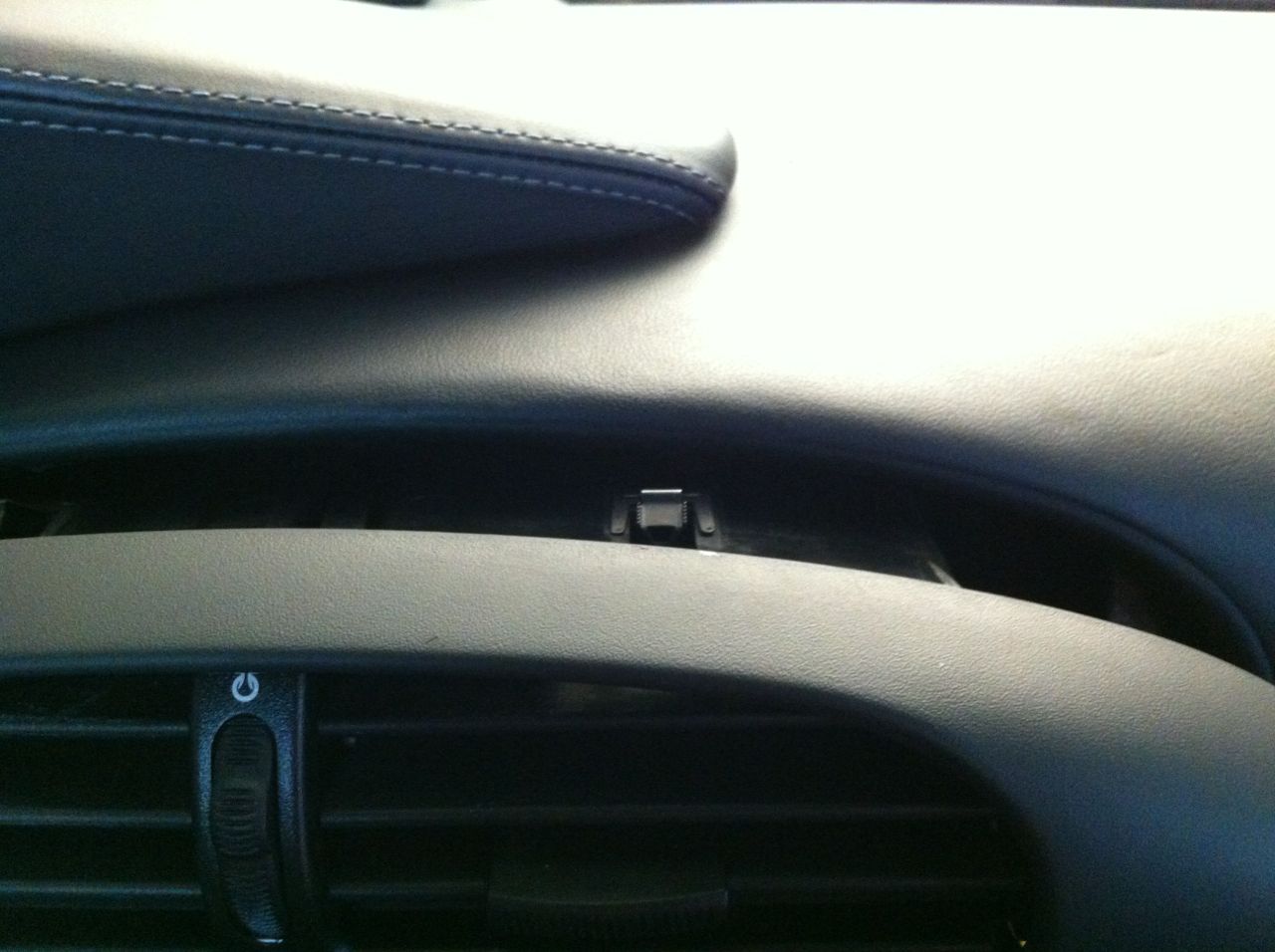
These are the hinges you need special tools for to pull them down and get the over out.
2. The rest is relatively easy. On each side of the PCM unit there is a spring. Push them inside and pull the PCM control unit out. There are no screws or anything, just the two springs in the middle of each side. Cover the car's sensitive areas with a blanket or so to not make any scratches.
3. The plug to look for is 'C' on the diagram. It is made up by three parts: yellow, green and blue. Remove it and take apart the plug. Remove the yellow part and apply it to the Solistor connector. Put it back in and re-attach the PCM unit. There is much space to run the solistor cable down behind the PCM CD Nav unit/ AC Unit. I decided to attach the Solisto with Velcro to the carpet between the cardan shaft and the air vents. There is also space behind the AC control unit. The iPhone cable went up to the telephone console. Done!
Reference: Porsche PCM1 Pinout
Borrowed from: Link Forum http://cuoresportivo.no
--------------------------------------------------------------------------------
Headunit
Naviunit
Disclaimer: THE PIN OUT CAN BE INCORRECT, USE AT YOUR OWN RISK.
All information is provided in good faith. Any modification you carry out, you do so at your own risk. No liability is implied or will be accepted. Please ensure that you are qualified to carry out any work detailed on this page and that you take all necessary precautions.
--------------------------------------------------------------------------------
Plug A
1 - Speed signal
2 - Free
3 - Free
4 - Terminal 30
5 - Terminal 30 for windscreen antenna
6 - Free
7 - Free
8 - Terminal 31
--------------------------------------------------------------------------------
Plug B
1 - Loudspeaker, rear right +
2 - Loudspeaker, rear right -
3 - Loudspeaker, front right +
4 - Loudspeaker, front right -
5 - Loudspeaker, front left +
6 - Loudspeaker, front left -
7 - Loudspeaker, rear left +
8 - Loudspeaker, rear left -
Note Plug B is assigned only if no amplifier is installed.
--------------------------------------------------------------------------------
Plug C
1 - Lineout, rear left
2 - Line out, rear right
3 - AF ground
4 - Line out, front left
5 - Line out, front right
6 - Terminal 30 for amplifier
7 - Control lead for CD changer
8 - Terminal 30 for CD changer
9 - Free
10 - Data lead
11 - Clock lead
12 - Reset lead
13 - Free
14 - Free
15 - Free
16 - Free
17 - Free
18 - CD AF, ground
19 - CD AF, left
20 - CD AF. right
Note Plug C consists of 3 parts.
Pins 1 to 6: yellow housing.
Pins 7 to 2: green housing.
Pins 13 to 20 : blue housing.
Pins 1 to 6 are the loudspeaker outputs to the amplifier. They are assigned only if an amplifier is installed.
Pins 7 to 12 are the control leads for the CD changer.
Pins 18 to 20 are the loudspeaker outputs of the CD changer.
Pins 7 to 20 are assigned only if a CD changer is installed.
--------------------------------------------------------------------------------
D-Antenna lead
--------------------------------------------------------------------------------
E-Fuse
--------------------------------------------------------------------------------
Plug I
1 - Video signal, red
2 - Video signal, green
3 - Free
4 - Free
5 - Free
6 - Terminal 31
7 - Free
8 - Free
9 - Free
10 - Terminal 30 for navigation
11 - Terminal 58 d
12 - Free
13 - Terminal 30
14 - Video signal, blue
15 - Video signal synchronisation
16 - Video signal ground
17 - Free
18 - Free
19 - Terminal31
20 - To combination plug IIIpin 6
21 - From combination plug IIIpin 11
22 - Free
23 - Fuel consumption signal
24 - Speed signal
25 - Free
26 - Terminal 30
--------------------------------------------------------------------------------
Plug II
1 - Diagnosis lead
2 - Terminal 15
3 - Terminal 86 s
4 - Data lead to navigation unit
5 - Free
6 - DSP (amplifier) ground
7 - Handsfree microphone ground
8 - Handset microphone
9 - Handset speaker
10 - Terminal 30, handset
11 - Free
12 - Voice output ground
13 - Voice output
14 - DSP (amplifier)
15 - Data lead from the heater / AlC unit
16 - Free
17 - Data lead from the navigation unit
18 - Free
19 - Free
20 - Handsfree microphone
21 - Handset ground
22 - Handset on-hook contact
23 - Free
24 - Free
25 - Free
26 - Free
-
Hi there
I'd like to remove my PCM 1 tomorrow to directly attach the Solisto Unit to the CD Changer port. At the moment I still have it in the trunk compartment including an iPod.
Is there anything special I need to look after? I searched the site and all DIY seem to be a bit different to my car:
1. I have cup holders
2. the panel that needs to be pulled forward is one piece from the cigarette lighter up above the airvents
Thanks!
Ronny
-
thanks amcleod1 for the post and videos! Great work. My noise stopped since it's above 0 degrees now and I don't bother till it stops again next winter :)


Glove compartment light
in 996 TT, 996 TT S, 996 GT2
Posted
I fixed the problem today, it was very much straight forward:
1) Remove the glove compartment dampers by carefully pulling them toward you, they are attached by a snap mechanism
2) Remove the 2 screws each side holding the glove compartment to the frame joint
3) the switch is top right, in my case the metal bracket just fell off
4) I removed the switch carefully with a flat screw driver, inserted the metal piece and fixed it with some epoxy that it will always stay there
5) works like a charm