Jump to content

Welcome to RennTech.org Community, Guest

There are many great features available to you once you register at RennTech.org
You are free to view posts here, but you must log in to reply to existing posts, or to start your own new topic. Like most online communities, there are costs involved to maintain a site like this - so we encourage our members to donate. All donations go to the costs operating and maintaining this site. We prefer that guests take part in our community and we offer a lot in return to those willing to join our corner of the Porsche world. This site is 99 percent member supported (less than 1 percent comes from advertising) - so please consider an annual donation to keep this site running.

Here are some of the features available - once you register at RennTech.org

  • View Classified Ads
  • DIY Tutorials
  • Porsche TSB Listings (limited)
  • VIN Decoder
  • Special Offers
  • OBD II P-Codes
  • Paint Codes
  • Registry
  • Videos System
  • View Reviews
  • and get rid of this welcome message

It takes just a few minutes to register, and it's FREE

Contributing Members also get these additional benefits:
(you become a Contributing Member by donating money to the operation of this site)

  • No ads - advertisements are removed
  • Access the Contributors Only Forum
  • Contributing Members Only Downloads
  • Send attachments with PMs
  • All image/file storage limits are substantially increased for all Contributing Members
  • Option Codes Lookup
  • VIN Option Lookups (limited)

Footwell Lights


Recommended Posts

I recently decided to place some bright white LED's in both the driver's side and passenger's side footwells of my '98 Boxster. The lights are super thin and come with a 3M adhesive. I placed the driver's side LED strip on the vent tube that runs horizontally and the passenger's side LED strip accross the bottom of the footwell foam cover in the natural grove channel. The foam cover is held in place by 2 screws with large heads. Both sets of lights are wired together and are joined together on the passenger side above the foam cover (and now new LED light) and connect to two (2) wires, positive and negative, that run up the passenger's side "A Pillar" trim piece, then accross the top and connect to the center interior light. The positive is soldered into the "Y" shaped copper rocker inside the light switch and the negaitve is wire tapped into the center wire entering the switch.

It has the same off/on properities as the door lights with the added flair of manual on/off by turning on the center interior light. The center interior light and now footwells can be always on, always off and door and locking activated.

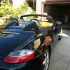
Here is a shot of the driver's side in my darken garage.

947578d9.jpg

Edited by kbrandsma
  • Upvote 3
Link to comment
Share on other sites

I have been researching this for a while. Very nice look and this would seem to be the simplest approach I have seen yet. Could you go into more detail about the LEDs? What brand? Where did you get them?

I purchased them from AutoZone for about $8.00. There are two (2) in a set. I have also seen them at PEP Boys. I'll snap a picture of them installed and post. They are each about 6" long and have 6 LED lights each. You can cut them in half at a determined spot that is clearly marked on each light. Each light has about 3 feet of lead wire attached. In the package they have a battery pack attached that allows you to test them before purchasing. They also come in other colors like blue, red or green. They are very thin (about the thickness of two quaters.)

Edited by kbrandsma
Link to comment
Share on other sites

Here are a couple of shots of the installed LED lights. The first photo is from the driver's side taken from the floor matt looking straight up. The light is attached to the bottom of the horizontal vent tube. The wire leads continue along the vent tube and then go through the center console and above the foam cover on the passenger's side. The second picture is the exact same shot on the passenger's side. The red/black wire leads on the passenger's side go through an opening I made with a pencil through the foam cover. To make sure there was good adhesion I used my heat gun to warm up the 3M tape as well as the tube and foam pad. You can see on the passenger's side that there is a natural channel that the lights are attached in.

Driver's Side:

d6c0a31d.jpg

Passenger's SIde

06bff5cc.jpg

I stand corrected. The cost was $15.99 not $8.00 for the pair and they are 8" long. I knew there was an eight in there somewhere. Below is a shot of an unopened package at AutoZone. You can also see where you can cut them to make them shorter. The next photo shows the thickness and the last shot is taken at night from the driveway with the car's parking lights on. They give you a good idea on how bright the LED's are when compared with the door lights.

635eeaa4.jpg

c97c0a29.jpg

c9065b7f.jpg

Edited by kbrandsma
  • Upvote 1
Link to comment
Share on other sites

  • 1 year later...
  • 1 year later...

Hi K.Brandsma,

I'm a new member and searching for info on footwell lighting for my 2003 Boxster S and found that you have done it on your car and I would like to know if you can share the wiring diagram and instructions so I may do it in my car as well. I would appreciate it if you can. Thank you!

artie400e

Link to comment
Share on other sites

  • 1 month later...

947578d9.jpg


1.  Per post #7 above, both sets of lights placed in the footwell are wired together.  The wires (positive and negative) meet on the passenger's side above the foam cover that is under the dash (foam cover is where the new LED light is placed on passenger's side).


2. These wires then are run up the passenger's side "A Pillar" trim piece, then accross the top trim of the windshield and connect to the center interior light switch.


3.  On the switch there is a "Y" lever that determines if the center light is always on, always off or only operates when the doors are opened. The positive wire from the footwell lights is soldered onto the "Y" shaped copper rocker inside the light switch.  


4.  The negative wire from the footwell lights is tapped into the center wire (ground wire) entering the switch. You can only do the positive wire to the switch and ground the negative elsewhere.  I chose to run them together. 


5.  The footwell lights now mimic the center console light including fading/diming after you lock the car. 

Edited by kbrandsma
Link to comment
Share on other sites

  • 4 years later...

Inspirational - but a couple things aren't quite right at least with my 98 Boxster. --- The forward and backward positions of the switch - but I got it figured out in case anyone else runs into this problem. I was trying to find out how to add door lights to my doors and where to power them - Found this posting and it set me on the right path. Saw the LED's in the footwells - great idea - could not find the exact ones but got something almost the same - tied the door lights and the LED's together - be careful to take note that the positive (+) must be run to the right connector(+) on the LED's or they won't work. Ran the leads up through the passenger A pillar - got them to the center light, tied the negative to the center wire on the connector and soldered the positive to the 'Y' rocker - door lights worked - no LED's - checked the center light with a voltmeter - found out the center wire on the connector is the positive and not the negative. After reversing them got the led's working, but the switch itself did not seem to be working exactly the way it should be. It "sort of" worked. Center worked with doors, and faded right but forward and backwards positions of the light did not seem to be working right. Also had a problem with the wire on the "Y" connector breaking pretty quickly - so I stopped to think about it. I took the switch apart and there are 2 small metal plates on either side of where the lightbulb attaches (+ and -) - that's the 2 connectors for the bulb and that's really what we want this to do - exactly what the center bulb does. 1 of these plates goes directly to the center lug of the connector (which is positive + not negative -), so if you splice the positive to the wire on the center connector that's good - but the other connector is actually the center lug BELOW the "Y" rocker - not the rocker itself - If you solder the negative to the "Y" the center position of the light works fine but the forward and backwards do not. If you solder the negative to the center lug BELOW the "Y" then BOTH wires that go to the doors and LEDS are tied to the same points as the center bulb. It also doesn't break the "Y" wire solder connection because there is no wire movement when the switch is rotated. It then does exactly what the center bub is supposed to do in all 3 positions, because the LED and door lights are then tied to the exact 2 connectors as the light bulb regardless of the "Y" positiion - which basically completes the circuit depending on position of the rocker switch - so you can turn ALL lights off or on at will - at least that;s how it ended up working on my 98 Boxster. It was a great help though because I didn't see anyone else explaining where to tie in the door lights, found the LED idea - and also liked the foot pedals and rest - so I bought something similar to that today also - thanks


Edited by jaz19
Link to comment
Share on other sites

  • 2 weeks later...

Create an account or sign in to comment

You need to be a member in order to leave a comment

Create an account

Sign up for a new account in our community. It's easy!

Register a new account

Sign in

Already have an account? Sign in here.

Sign In Now
×
×
  • Create New...

Important Information

We have placed cookies on your device to help make this website better. You can adjust your cookie settings, otherwise we'll assume you're okay to continue.