Welcome to RennTech.org Community, Guest
There are many great features available to you once you register at RennTech.org
You are free to view posts here, but you must log in to reply to existing posts, or to start your own new topic. Like most online communities, there are costs involved to maintain a site like this - so we encourage our members to donate. All donations go to the costs operating and maintaining this site. We prefer that guests take part in our community and we offer a lot in return to those willing to join our corner of the Porsche world. This site is 99 percent member supported (less than 1 percent comes from advertising) - so please consider an annual donation to keep this site running.
Here are some of the features available - once you register at RennTech.org
- View Classified Ads
- DIY Tutorials
- Porsche TSB Listings (limited)
- VIN Decoder
- Special Offers
-
OBD II P-Codes - Paint Codes
- Registry
- Videos System
- View Reviews
- and get rid of this welcome message
It takes just a few minutes to register, and it's FREE
Contributing Members also get these additional benefits:
(you become a Contributing Member by donating money to the operation of this site)
- No ads - advertisements are removed
- Access the Contributors Only Forum
- Contributing Members Only Downloads
- Send attachments with PMs
- All image/file storage limits are substantially increased for all Contributing Members
- Option Codes Lookup
- VIN Option Lookups (limited)


RJFabCab
-
Posts
106 -
Joined
-
Last visited
Content Type
Profiles
Events
Forums
External Paint Colors
Downloads
Tutorials
Links Directory
Collections
Store
Posts posted by RJFabCab
-
-
The clutch hydraulic system on a TT is filled up with PENTOSIN hydraulic fluid, look out with that. The canister is located under the trim on the left of the battery. If a bleeding of the clutch system is not necessary, let it like it is.
That's interesting info. I just got done reviewing PET diagrams and it looks like the following:
1. In the 996 non-turbo cars, including the 996 GT3, the brake lines and clutch operating cylinder are run off the same fluid, brake fluid, with a common reservoir.
2. The 996TT and 996 GT2 have separate circuits with different reservoirs. The brake lines are fed with brake fluid while the clutch hydraulic lines are fed with PENTOSIN.
3. The 997 non-turbo cars, including the 997 GT3, appear to have the same setup as the 996 non-turbo series. Brake lines and clutch lines have a single brake fluid reservoir.
4. The 997TT, same as the 996TT, has separate circuits. Brake lines are fed from the brake fluid reservoir while the clutch hydraulic lines are fed from a separate reservoir containing PENTOSIN.
Thanks, RFM. I really didn't want to stick my arm way up under there anyway! :lol:
-
Loren et al,
I plan on changing the brake fluid in the 997TT with a Motive Power Bleeder.
Is the clutch bleed valve in the 997TT still accessible and in the same location as in the 996 series (top of the tranny)?
Are there any significant technical/procedural differences that I need to be aware for the 997 series?
I haven't actually gotten up under the car yet, but the procedure surely can't be that much different from the 996.
Cheers
-
Motorcycle mode: 14.4 Volts at 0.8 A (Primarily for batteries of the less than 14 Ah)
Car mode: 14.4 Volts at 3.3 A (for all batteries greater than 14 Ah)
Excellent.
Thanks, Loren!
-
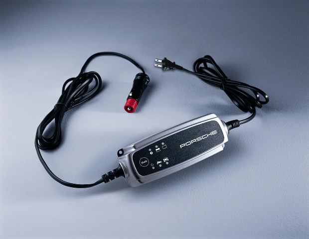
Does anyone know the charging specs for the Porsche battery maintainer? Specifically, what are the spec differences between motorcycle and auto modes?
I'm talking about the long, slender maintainer that looks just like a CTEK unit (see pic). I have 2 of these and I can't find the owner's manuals. I also can't seem to find the exact same CTEK model to reference specs. Is the manual online somewhere?
I just picked up a Braille AGM sealed battery for the GT3 and need to know if the Porsche maintainer will be appropriate for use with the Braille battery.

-
I wish I did...
I'm still trying to figure out why 15W-40 Mobil 1 came off the approved list after being - practically the only approved oil for 5 years.
I guess further testing of oils and engine wear must lead to this (along with Mercedes and BMW having longer intervals too).
Thanks for the response, Loren.
So, is PST2/PIWIS the only way to reset my service indicator? Durametric's website doesn't have a tool listed for the 997TT... only the base 997 and the 996TT are mentioned.
Can the dealer reprogram my service indicator to go off in 2 year intervals?
Interesting... I just got back from Wally Mart with a case of 15-40... j/k!!! :D
-
This is in reference to my 2007 997TT.
My maintenance schedule booklet dated 5/07 lists 'first minor maintenance (years 1, 4, 7...)', 'second minor maintenance (years 2, 5, 8...)', and 'major maintenance (years 3, 6, 9...)'. Each service includes an oil change... which means the oil needs to be changed once per year if mileage limits are not met.
My service indicator in the OBD is telling me to head in for service (one year has passed).
The maintenance schedule booklet here on Renntech is dated 9/07 and alternates between a minor service (years 2, 6, 10...) and a major service (years 4, 8, 12...) which means oil changes every 2 years if mileage limits are not met.
Why the difference and why the change? Per the latest 9/07 schedule, I should just head in for the dealer to reset the service indicator.
It looks like my '02 C2 cab required annual oil changes if driven < 9K miles/yr, and then in 2004, Porsche recommended oil changes every 2 years for the base Carrera and even the 996 GT3, and then my 5/07 booklet says annual oil changes again, and then the 9/07 document says every other year for oil changes.
WTFrick is going on here???
Loren, do you have a good explanation for this one? :P
Thanks! :renntech:
RJ
-
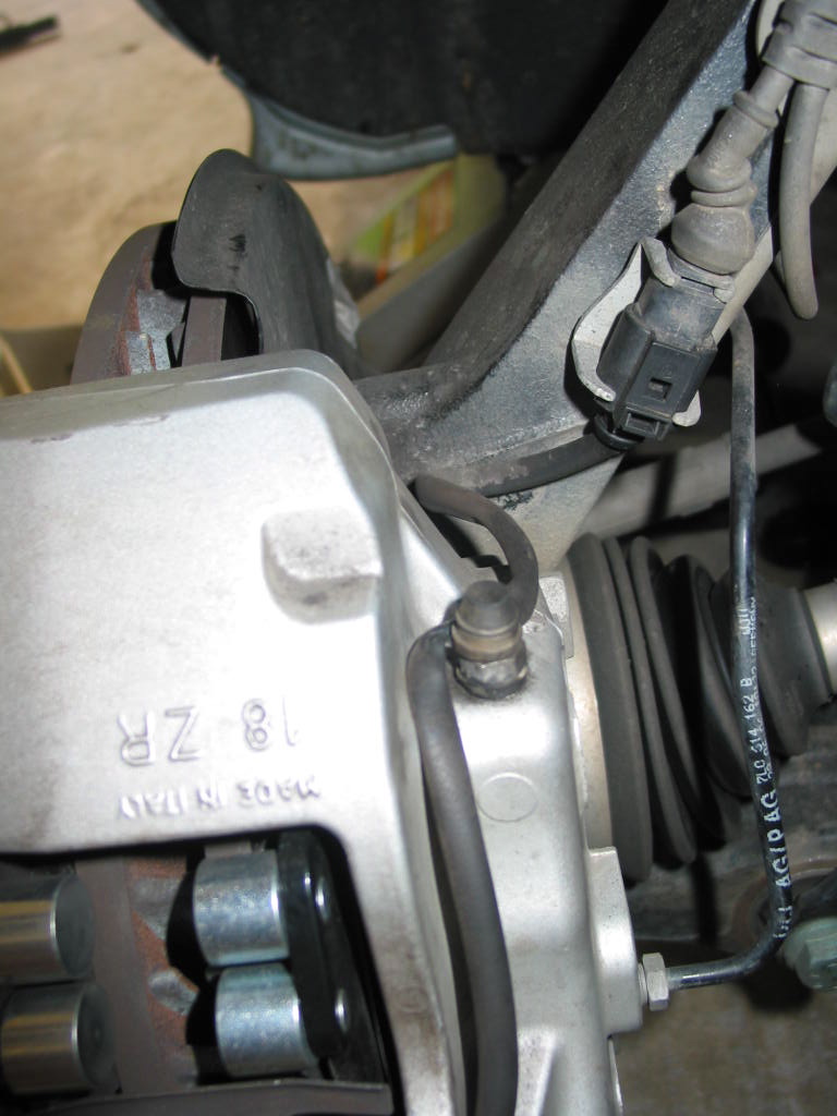
I completed the brake fluid flush with ATE Typ 200 and a Motive power bleeder. It was a little difficult to keep an eye on the fluid level in the reservoir due to the gold color and the hidden nature of the reservoir, but the procedure was very straight forward.
I could have done the entire job with one liter, but I wanted to be extra thorough with all the bubbles and debris flying out of the nipples, so I ended up using 1.25L. Interestingly, "ATE" is molded into the brake fluid reservoir.
The only point of interest, sort of, is that the factory routes the brake pad sensor wires through the rubber covers for the bleed nipples as shown below.
-
 1
1
-
-
I sent you a PM.
Thanks, Loren. I did the right rear and then it started to RAIN!!! LOL So, I just moved the truck inside the garage... and onto the left rear. Since I'm working solo, I'm not pumping the brakes while bleeding.
When I moved the truck inside, the pedal felt fine. I use the Pepper to tow and noted quite a bit of debris in the fluid at the right rear (15K miles on the odo) but no bubbles.
I can't imagine the pumping the pedal procedure being necessary unless there was a significant amount of air in the system.
Thanks again for the help. :renntech:
-
I have much experience on 996 brakes and recently changed the front pads on the Cayenne S. Now, I'm about to flush the Cayenne S brake system with new ATE Typ 200 DOT 4 fluid.
Renntech search yielded one pertinent hit RE MY2004 Cayenne brake flush and Loren's response was that the procedure is basically the same as a 996. Cayenne manual states that the flush takes about 0.95 liters.
A couple of Q's:
1. Do the same pressure rules apply for the Cayenne? Keep the Motive bleeder less than 20 psi at the master reservoir?
2. It's a Tiptronic. Are there any other lines connected to the brake fluid reservoir that need to be bled besides the 4 calipers?
Cheers
-
Loren, do you know of any failures (either in the case or at the tranny interface) related to jacking the vehicle from the case? Surely, the case wasn't 'designed' for that.
I have been dealing with GT3 Cup cars and street cars since the first Cup cars came over from Kadach (German firm that sells used Cup cars) Not one time have I seen a failure or heard of one (and I deal with shops and race teams 24/7)
You are correct in saying: the case was never designed for that, but it was also not designed for 1000hp twin turbo setups (but they work fine)
I'll see if I have a recent pick of your "Made in Spain" engine case and show you the internal webbing. You'll see quickly that is "Ok" to lift them there. Your case really isn't much different than all the cases before it (66-98) and we have been lifting 911's like this since 1966 (not me.. I was born in 70.. lol) but you get my point.
Now, that being said, The tech who lifted the car should be *shown* how to use a small piece of wood in the center of the jack pad to keep this from happening.. or they need to BUY the proper pieces for their lift if they are going to TOUCH 986/996/997 chassis'
I'd be miffed also
B
Thanks, Brad.
It was a loooooooooong day at work and I'm just now catching up on all this! As noted in my response to Craig, I felt some ridges near the indentation last night and was too tired to figure out what was really going on... I thought those ridges may have been something bent or compromised. Later I realized that the ridges are cast into the case.
The 'dent' looks cosmetic. BUT IT STILL P*SSES ME OFF!!! LOL
Thanks for the reassurance and if you find those pics of the inners of the Spain cases please post them. :thumbup:
-
Hi RJ.... There is a lot of disagreement on whether it's OK to lift the rear of a 911 (with the classic engine case, not the flat bottom as Loren points out) with a floor jack under the engine case. I've seen 911's lifted that way forever with no obvious damage......I've seen factory trained techs lift them that way.....even Turbos and recent GT cars that are heavier in the rear than the early cars. I've seen our local trusted certified tech list my own GT3 a few inches to get it on his lift. BUT, all that said, I don't lift my own car that way myself and don't ever plan to. Personally, I just think it's safer not to. If you have ever had an air cooled (or later GTcar) engine apart, you can envision the engine case structure. It's there to support the crank, barrels, heads, flywheel, etc. There is a nice mating flange to the two side of the case, but, it is definitely not a factory intended lift point. I've never seen any factory material recommending the case as a lift point. I can just imagine the lifting forces radiating through the case material from a localized lift/contact point on the bottom of the case. Also, Porsche has gone to great lengths to lighten the rear end of a 911 over the years (magnesium cases for engine and transmission come to mind) and I'll bet they have not added extra material to the engine case to accomodate lifting there. I'm sure others might have different opinions on the subject....this is just mine. That said, and given that I've not ever seen obvious damage as a result of lifting at the case, I'd say that no obvious damage has been done to your car.
Craig, thanks for the reply.
I know guys have been lifting from the case for years... I'm just not a big fan of the procedure for the reasons you list above. It is reassuring, however, to have the input from Brad's post.
The indentation from the jack looks cosmetic. Late last night when I was trying to look at the case I felt some ridges near the indentation but I didn't really get a good look at things since it was late and I was dog tired. I thought something may have been bent or compromised, however, I later realized that those ridges are simply cast into the case.
I'm peeved that the guy didn't use something to protect the case like a piece of wood or a hockey puck!!!
-
Jeez... tell them to buy a hockey puck.
I think you are ok if there are no further cracks on chips.
Thanks for the feedback. I'm angry at myself for not keeping an eye on them... but should I HAVE TO??? :angry:
Loren, do you know of any failures (either in the case or at the tranny interface) related to jacking the vehicle from the case? Surely, the case wasn't 'designed' for that.
The mechanic is from a Porsche race team in the 80's out on the west coast. Unbelievable.
-
Take a good look at my crank case and tell me what you think. There are three pics.
The car was at a local shop for a tech inspection and while they were loading it onto a nice Rotary lift, I was checking out some of the old P-cars in the shop.
I turn around and guess what I see... the arse of my car is in the air being jacked up by the bottom of the crank case! :soapbox:
No, I'm NOT a fan of jacking up the car by the case.
The car was too low to get on the lift, so they jacked the rear from the case to get the lift under the four jack points. I didn't notice them jacking up the rear since I was checking out other rides. :eek:
When the inspection was done, they had to jack the rear again to get the car off the lift.
I checked the case bolts and all seems tight. No obvious cracks or leaks in the case anywhere, however, there is a large indentation in the vertical fin of the left side of the case (outlined in the link above). I think the indentation is where the rough edge of the jack met the case.
Should I be worried about the crank case or is this just a cosmetic issue that should never have occurred in the first place?
-
the oil is too clean to see when the level is on the stick, anyway. I just use the electic dash read out to evaluate oil level.
Craig, thanks for the reply.
I did a thorough draining and then refilled her with 7.75 US quarts... just to be safe. I couldn't see squat with the dipstick for the very reason you mention above. :blink:
But the dipstick proves it... I have a Cup car! :lol:
Anyhow, .25 quarts more and the e-gauge read about one bar above the middle of the range. I barely got in 8 quarts. It's far too easy to overfill the engine. I ended up filling the oil with the dipstick removed.
Cheers
-
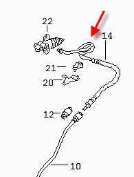
The 2 parts in your pic are technically all you will need to go back to stock. However, your OEM plastic bushings were discarded with the B&M install. Just mount the OEM shift stalk within the B&M aluminum bushings.
The EVO link is simply replaced by the OEM spring loaded connector in your pic.
The job is a straightforward DIY, but I would recommend getting the plastic centering tool to help you realign the cables with the install. Also, get some grease to help the spring loaded connector back onto the ball end of the shifter stalk.
-
The oil filler tube contains a dipstick inside of it.
When you're adding oil to the car, do you leave the dipstick in place and then pour around it?
Or, do you take the dipstick out and then pour down 'both' tubes?
The manual is not clear on this.
It seems like it would take forever to add 8-9 liters with the dipstick in place.
Cheers
-
Bingo. I finally got to the valve... what a PITA. <_<
I tried to access it with the rear up on tire ramps. I could see it, but I couldn't reach it.
With the left rear wheel off, I could reach the valve with my arm stuck all the way through to the top of the tranny.
7 mm (6 point) hex wrench was a tad too big, but a 7 mm (12 point) hex wrench fit perfectly.
Cheers
-
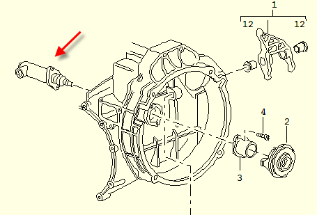
Yes, hydraulic line.
Clutch slave cylinder goes here (roughly).
Thanks, Loren!
:cheers:
-
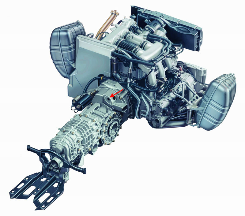
It should be in about the same postion. Very high near the bell housing. You should be able to follow the hydraulic line to it - it has a loop or two in it.
Loren, am I going blind? Ok, don't answer that. :P
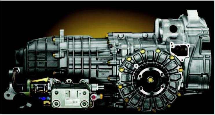
This is a shot of an '04 GT3 tranny from a Porsche pdf document. I am oriented to the diagram you attached, but can you see the valve in the following pic?
When you mention "loops", are you talking about loops in the hydraulic line?
I'm going to try and go after it tomorrow.
-
Hey, Loren... would you happen to have a pic or diagram of where the clutch bleed valve is located on the Mk2 GT3?
I bled the brakes today, but I couldn't find the clutch valve. It was pretty tight up under there, and I looked all around the driver's side of the tranny. I did see what appeared to be maybe a 5-6mm hex on top of the tranny, but I wasn't sure if that was it.
On my '02 C2, the clutch bleed valve is in plain sight, but I couldn't find it today on the GT3. :eek:
Cheers
-
996 GT3: Replacing front rotors
Instructions for changing the left front rotor: Proceed at your own risk. B) 1. Lift and safely support the vehicle. 2. Remove the left front wheel. 3. Turn the steering wheel to the right to facilitate exposure of the rotor and caliper assembly. 4. Loosen the brake pad retaining bolt (13 mm hex) and depress the retaining flat spring. The 13 mm hex head is on the inside edge of the caliper (not visible in the pic below). Take note that the flat spring is VERY stiff. 5. Remo
-
Author
-
Category
-
Submitted07/30/2006 11:07 AM
-
-
Thanks, Loren!
I cut straight to the chase and missed the 'edited' line about the supplement #98.
Thanks for the clarification.
BTW, I'm ready to put together the DIY GT3 rotor post.
RJ
-
I just noticed in the DIY section that when bleeding the clutch, the instructions mention "pumping the pedal". Please help clarify the following:
"Open the clutch bleeder valve until clear, bubble free brake fluid emerges (at least 30 seconds according to Porsche). Remove the wood. Then, pump the pedal again very slowly by hand for a further 60 seconds. After pressing the pedal down fully about 10 to 15 times, leave the pedal in its normal position. After allowing a fill time of 90 seconds, check that no more air bubbles appear at the bleeder valve (use a collecting bottle with a transparent hose). Then close the bleeder valve. Wipe off the area and replace the rubber protective cap over the bleed screw.
You may notice that the clutch pedal does not return... so carefully pull it up (slowly) to it's normal position. Then depress it (slowly) a few (at lease 5) times. In a few cycles the feel should return"
Does this mean the following:
1. Motive bleeder is hooked up and pressurized.
2. The clutch pedal is fully depressed.
3. The clutch bleed valve is opened and then closed once bubble free fluid emerges.
4. The brake pedal is pumped very slowly by hand 10-15 times over the course of 60 seconds?
5. Wait 90 seconds, and then rebleed the clutch valve until bubble free fluid emerges. Close the clutch bleeder valve.
6. Slowly pull up the clutch pedal (I do it over about 1 minute) and then cycle the pedal slowly several times until the clutch pedal 'feel' returns.
7. Move on with bleeding the rest of the system.
This question arises because I don't remember the "pump the pedal" portion of the DIY instructions. I have had to rebleed my clutch on more than one occasion due to spongy feel related to air in the clutch only.
So, the brake pedal should be pumped while the system is under pressure (with the Motive bleeder) and the clutch bleeder valve is closed? Or, should the clutch bleeder valve be open while pumping the brake pedal and the system is pressurized?
The latter seems to make more sense.
Cheers
-
Pictures from Oakland.
Jeff, thanks for the pics. I was tired and moving fast... :eek: djantlive, thanks for the reply.
I installed the new element and then the filter housing over it. As I tightened the housing I felt the crunch that speed123 described. That made me wonder if I had pushed the new filter element up high enough into the engine. So, I took the filter housing off again, and this time the filter element came off with the housing, and the filter was sort of stuck in the bottom of the filter housing... like something was holding it in place (this must have been the spindle assembly mentioned in Loren's DIY).
So, I took the filter out of the housing and reinstalled it to the motor after making sure that it couldn't be pushed up any further. The filter element just sort of hangs in mid air. Then, I reinstalled the filter housing cover, felt the slight crunch again, and continued to torque it down to spec.
Apparently this is all part of the process and normal. Thanks to all.


Question: OBD code P2099
in 997 TT, 997 GT2
Posted
This is in reference to my '07 997TT with FVD sport headers and FVD sound version exhaust with 200 cell cats. Everything else on the car is bone stock including the ECU program. She runs just fine.
The car is low miles and the full exhaust has been on the car for over 3 years. I get random CELs, only 2-3 times, with OBD code P2099 "Post Catalyst Fuel Trim System Too Rich Bank 2".
These are my thoughts:
1. Cat going bad
2. O2 sensor going bad
3. 'Occasional' random CEL due to the high flow setup
4. Bad gas
My guess is that it's not a big deal, and I have reset the code. I will probably have the dealer check it out just to be sure all is good.
Am I missing something here? Any other thoughts to add? I hardly drive the car... it has 10K miles on the clock.