Welcome to RennTech.org Community, Guest
There are many great features available to you once you register at RennTech.org
You are free to view posts here, but you must log in to reply to existing posts, or to start your own new topic. Like most online communities, there are costs involved to maintain a site like this - so we encourage our members to donate. All donations go to the costs operating and maintaining this site. We prefer that guests take part in our community and we offer a lot in return to those willing to join our corner of the Porsche world. This site is 99 percent member supported (less than 1 percent comes from advertising) - so please consider an annual donation to keep this site running.
Here are some of the features available - once you register at RennTech.org
- View Classified Ads
- DIY Tutorials
- Porsche TSB Listings (limited)
- VIN Decoder
- Special Offers
-
OBD II P-Codes - Paint Codes
- Registry
- Videos System
- View Reviews
- and get rid of this welcome message
It takes just a few minutes to register, and it's FREE
Contributing Members also get these additional benefits:
(you become a Contributing Member by donating money to the operation of this site)
- No ads - advertisements are removed
- Access the Contributors Only Forum
- Contributing Members Only Downloads
- Send attachments with PMs
- All image/file storage limits are substantially increased for all Contributing Members
- Option Codes Lookup
- VIN Option Lookups (limited)


996noob
-
Posts
243 -
Joined
-
Last visited
Content Type
Profiles
Events
Forums
External Paint Colors
Downloads
Tutorials
Links Directory
Collections
Store
Posts posted by 996noob
-
-
What is the equivalent to the ATF fluid used for the 997.1 Tiptronic?
Can we use the same fluid as the 996 Mk2?
Out of curiosity, does anyone know what the 997.1 Trans is based on? ZF of some type, or MB of some type? This info could help identify the proper ATF fluid to be used.
-
Indeed C14 was very clearly marked! Thanks for the help.
Unfortunately there is no readilly available switch I am familiar with. The switch you see in my post was self made along with the bracket , I made a few kits up as spares to sell to anyone that wanted to save the time and hassle of making their own. D6 is a pulsed input from the switch panel. A11 is feedback from the DME to illuminate the PSE switch. When you remove the plugs from the DME its easy to see which chamber is C14 if you look closely at the plug the chambers are labelled at each end eg 11 and 20. Just make sure you remove the correct plug and carefully SLIDE the block connectors from the cover before trying to add any new cables. If you decide not to use the DME to control the PSE you can wire directly from a 12V switch to the PSE actuation solenoid , the other side can connect direct to ground/ earth.
-
I know that the Mk1 996's with ZF automatics and the 987 Cayman/Boxster S 3.4L use LT71141 ATF. What do the 997's use? The same as the Mk2 996's?
Is the 997 Tiptronic Mercedes Benz based too?
Sorry, you will need a PIWIS and and ATF charging unit to top up the Tiptronic.
-
After battery disconnect, I get fault code 4444 read by PIWIS, steering angle sensor not initialized, on a 997.1. I folllowed the repair manual procedure which is, start engine, turn left 20 degrees, turn right 20 degrees and drive more than a certain speed for more than 6 seconds in the straight ahead position. There is no error on the instrument cluster anymore. However, 4444 isstill read by PIWIS, and the details of the error seem to indicated that PSM is active, etc. Is this error code just temporary and will be erased after awhile?
-
After re-reading your post, I am trying to differentiate between the momentary (non-latching) input of D6 and A10/A11, which you have mentioned are responsible for internal DME latching of the PSE solenoid earth wire.
Also, another question that comes to mind is, if I go the conventional swicth way, using a switched 12V as power while controlling the earth to trigger the PSE solenoid, is there a part number to nice looking conventional switch that has an exhaust logo that I could use? (Porsche or even other car brand)
The 987 and 997 use the same rear DME , the DME switches to earth on pin C14 and D17, so the PSE needs to have a live feed to one side of the solenoid and connected to the DME (ground) on the other. I used the 997 and 987 PSE install instructions to determine which pins needed to be connected. It depends on the model year of your car as to which pin is used , C14 if its 2005 and D17 if its 2006 or later. I believe the differences are around whether the PSE control wiring is present in the engine bay (ie brown plug that connects to the PSE solenoid is pre wired back to D17 on the DME)
The dashboard switch for PSE activation comes either from the sport button (if sport chrono is already fitted) or from a separate PSE button for which you need a mini wiring loom and new switch panel with the button . In either case the input to activate the PSE goes into chamber D6 on the DME plug. This input in turn activates an internal relay which switches either C14 or D17 to ground so making the PSE active or inactive. C14 and D17 are automatically switched by internal logic between 30 and 40 mph so the PSE becomes "quiet" to satisfy european noise regulations.
A10 and A11 are the switch panel. One side of the switch is the input to the DME ( a pulsed input from the switch, the DME does the latching control of the output C14/D17 ) the other is the LED that illuminates when the button is active. As a result there is no way to replicate the switch control into the DME using a simple latching switch , you have to bypass the DME control and install a dedicated 12V circuit , direct to the PSE solenoid.
If you dont have sport chrono (or the PSE mini loom and new switch panel) you need to find a switched live supply to feed the PSE solenoid and fit a simple pushbutton to activate it. If you do not use a switched 12v supply (most of the wiring loom is actually permanent 12v on the 997/987) then you run the risk of flatenning the battery if you leave the PSE switch depressed (ie in quiet mode) as the solenoid constantly draws power.
If you subscribe to the forum (become a contributor) you get access to all the tech bulletins including the one for the 997 PSE install. The install on planet 9 you refer to was written by myself . The picture of the grey plug is not the C plug , its just for reference only , hence C14 is populated in the pic. Sorry for any confusion
-
Hi Berty,
Thanks for the clarification! Indeed, the grey connecter with the populated C14 threw me off.
I am a contributing member and have the TI for the 997 PSE install. Thankfully, my 997 has Sport Chrono, so I only have to wire up to the DME and no additional wiring to the switch is necessary. However, before I get there, is C14 clearly marked on the C plug? That is basically my only question, other than how difficult is it to get through that large rubber grommet in the engine bay. I've done the 996 install before, as Orient pointed out, but that is only through the small rubber grommet, quite manageable, compared to the large one tucked away in the corner of the engine bay of the 997 that the wire is supposed to go through.
Thanks in advance.
The 987 and 997 use the same rear DME , the DME switches to earth on pin C14 and D17, so the PSE needs to have a live feed to one side of the solenoid and connected to the DME (ground) on the other. I used the 997 and 987 PSE install instructions to determine which pins needed to be connected. It depends on the model year of your car as to which pin is used , C14 if its 2005 and D17 if its 2006 or later. I believe the differences are around whether the PSE control wiring is present in the engine bay (ie brown plug that connects to the PSE solenoid is pre wired back to D17 on the DME)
The dashboard switch for PSE activation comes either from the sport button (if sport chrono is already fitted) or from a separate PSE button for which you need a mini wiring loom and new switch panel with the button . In either case the input to activate the PSE goes into chamber D6 on the DME plug. This input in turn activates an internal relay which switches either C14 or D17 to ground so making the PSE active or inactive. C14 and D17 are automatically switched by internal logic between 30 and 40 mph so the PSE becomes "quiet" to satisfy european noise regulations.
A10 and A11 are the switch panel. One side of the switch is the input to the DME ( a pulsed input from the switch, the DME does the latching control of the output C14/D17 ) the other is the LED that illuminates when the button is active. As a result there is no way to replicate the switch control into the DME using a simple latching switch , you have to bypass the DME control and install a dedicated 12V circuit , direct to the PSE solenoid.
If you dont have sport chrono (or the PSE mini loom and new switch panel) you need to find a switched live supply to feed the PSE solenoid and fit a simple pushbutton to activate it. If you do not use a switched 12v supply (most of the wiring loom is actually permanent 12v on the 997/987) then you run the risk of flatenning the battery if you leave the PSE switch depressed (ie in quiet mode) as the solenoid constantly draws power.
If you subscribe to the forum (become a contributor) you get access to all the tech bulletins including the one for the 997 PSE install. The install on planet 9 you refer to was written by myself . The picture of the grey plug is not the C plug , its just for reference only , hence C14 is populated in the pic. Sorry for any confusion
-
I've done a 997.1 PSE install, but haven't got to the electrical bit yet which will be "part 2".
Going through the Technical Information on the electrical connection to the DME, I need to tap onto A8 and connect to C14.
Before I get into the actual DME connectors I was wondering if the the pin numbers are clearly marked on each connector.
What threw me a bit off was this Boxster PSE install on Planet 9 http://www.planet-9.com/reviews/miscellaneous/p294-retrofitting-factory-pse-and-overide-switch-porsche-sport-exhaust-pse.html .
Grey/Green C14 needed to be connected in this case as well. If you look at his connector it looks like he added the Grey/Green wire to C17 instead, yet he mentions he needs to wire to C14.
Anyone done the 997.1 PSE install can shed some light on this?
Also, how difficult was it to route the wire through the rubber grommet on the right side of engine bay to the car's interior? Any tips?
-
What's the difference between the PSS10 you've given the link to, and B16 Damptronic that is designed to work with PASM? Or are they one and the same?
Most guys just get the stiffer pss10 shocks like below.
http://www.automotio...ml?dept_id=4994
A gt-3 is about 1" lower. It would be alot cheaper to buy a gt-3 then
to buy all the gt-3 suspension parts. You may even need to buy gt-3
half shafts for the suspension to work.
Paul
-
Was referring to the springs/shock absorbers from the GT3 (w/PASM), and if the PASM will work when they are connected to the C2S.
A few guys have added lower GT-3 suspension links. They
have adjustments that you can make at the track.
Paul
-
Can the GT3 suspension w/PASM work on the 997.1 C2S w/PASM? Are the PASM on both cars the same?
-
I'm ordering this kit for a friend. However, supplier says kit number is 997 044 201 03. This puzzles me. Is it the latest number now?
99704420002Thanks Loren in advance, sent a portion of my contribution over today as well for all the help
Sam
Thank you again for your contribution.
Sport exhaust for MY05-08 997-1
997.044.200.02 replaced 997.044.200.01
and
997.044.200.03 replaces both.
So,
997.044.200.03 is the current part number.
Any difference between the 3 numbers?
I just purchased the 02 for my car and got a pretty good deal on it (am I allowed to post prices?) I got it from an OPC down in Jersey and it is getting shipped to me this week. Comes with Mufflers L/R, PSE tips and wiring.
I've been trying to contact the guys at "suncoast" but they're giving me a bit of trouble, not providing me quotes unless I sign a CC authorization with them for an amount prior to my order which makes no sense to me.
I would love to use them, but the lack of service is changing my mind.
Sam
Most likely just vendor changes. One is likely as good as the other.
-
The routing and attachment of the vacuum lines for a 997 PSE is identical to that of a 996. Here is a link to the description of my 996 PSE install and the vacuum line routing.
I'm thinking of embarking on an interesting project. Could I use the circuit from the 996 PSE to control the 997 PSE changeover valve, so that regardless of the 997 DME setting, I can have a latching switch turn on or off the exhaust (like the 996).
Somehow take the whole circuit with relay, and put that in a 997 to control the PSE. But could I use the Exhaust Button from the 997 instead of the oval 996 one?
Any thoughts/advice?
-
Noob:
IIRC, ALL Porsche part numbers that have a different part for the left side and for the right side generally use the convention that has an EVEN number for the part on the right side and an ODD number for the part number on the left side in the three digit number before the version number.
Regards, Maurice.
Thanks!
-
Their have been 4 upgrade/updates to the rotors.
Here is what I show for the latest parts:
Left front - 996.351.031.095
Right front - 996.351.031.095
Left rear - 997.352.031.00
Right rear - 997.352.031.00
Fronts have an MSRP of about $4200 each - rears about $3600 each
Did you mean;
Left front - 996.351.031.95
Right front - 996.351.032.95
Left rear - 997.352.031.00 (some places list 997.352.031.01)
Right rear - 997.352.032.00 (some places list 997.352.032.01)
I'm still in a state of confusion, and worried about getting the wrong part.
-
Model and year of the car you want to put these on please?
And, is this new or replacement?
Replacement on a 2003 996 GT3 already equipped with PCCB.
However, the catalogue says up to '04 cars use rotors ( A ), and '05 onward use rotors ( B ), which in turn are superceded to rotors ( C ).
Pads, Calipers, Bearing Carriers (uprights) seem to be the same throughout all years, so it would be good if I could go straight to rotors ( C ), especially if they have improved design.
Advise really appreciated. Thank you, sir.
-
What do you mean by different versions? There is one set of PCCB and another set of steel rotors.
PCCB rotors:
Front Left: 996.351.031.92
Front Right: 996.351.032.92
Rear Left: 996.352.031.02
Rear Right: 996.352.032.02
Need some urgent help in this department.
According to the parts catalogue, there are:
Front Left:
( A ) 996 351 031 02 -04
( B )996 351 031 03 05-
( C ) 997 351 031 00 supercedes ( B )
Front Right:
( A ) 996 351 032 02 -04
( B ) 996 351 032 03 05-
( C ) 997 351 032 00 supercedes ( B )
Rear Left:
( A ) 996 352 031 02 -04
( B ) 996 352 031 03 05-
( C ) 997 352 031 01 supercedes ( B )
Rear Right:
( A ) 996 352 032 02 -04
( B ) 996 352 032 03 05-
( C ) 997 352 032 01 supercedes ( B )
we can conclude that ( C ) supercedes ( B ),
but does ( B ) supercede ( A )?
If it does, then it is much easier, just get ( C ) in all cases.
Can someone with the knowledge advise?
Since the value of these parts are so high, I don't want to make a mistake!
Thanks!
-
I just replaced my water pump on my 1999 996. I was wondering if I should have replaced the thermostat as well? I'm a bit concerned that I did not.
Thanks,
Harry
Harry:
It's only four 10mm bolts, one radiator hose clamp, and a partial coolant drain to replace the T-stat. If you have tackled the water pump yourself, it should be an easy DIY for you.
If you are only replacing the T-stat, I understand that a special tool is required to remove the T-stat from the housing, but IIRC the tool can be improvised.
Regards, Maurice.
How to improvise the thermostat tool? Does anyone have pictures?
-
Read the intro at the top and there is your answer. But, briefly, remove the right side air vent, unscrew the air duct which then loosens the black pipe underneath the dash. Remove this pipe; lay on your back in the passenger footwell and with a 13 mm socket, take out the air bag bolts. - About 30 minutes or so.
Tools -wise, anything special required? Is that a Torx driver? What sizes of Torx were needed?
-
The differential part of the Tiptronic use a manual gearbox/differential oil, 75w-90 should be fine, so certainly do not use ATF for the differential part. Only the older Tiptronic have a drain plug, you can suck out the old oil using the filler plug in case you decide to service the differential oil on a younger type.
Thank yoiu RFM, for the info. I'll look out for the differential drain plug when I do my ATF fluid change. I guess its location is obvious when I'm there?
-
Just a little off topic here, hope you don't mind. For a '98 996 with the ZF tiptronic, is there a separate gear oil for the differential? Or does it share the oil with the ATF (I hope not) ? Is there a DIY prosedure somewhere on the Forum? And what is the gear oil spec? 75W-90 GL5?
Is this the same case for the newer version Tiptronic (MB based transmission) as well (apart from the difference in ATF type used)?
Haven't seen this topic being posted before, so I thought I should ask.
Thanks in advance.
For a 2003 996, everything I've read says Mobil 1 synthetic ATF is more than compatable w/the required ATF 3353. Your thoughts/experience in the synthetic ATF arena is greatly appreciated.
Thanks,
Denny
-
Thanks Maurice, I'll rememebr to do that.
-
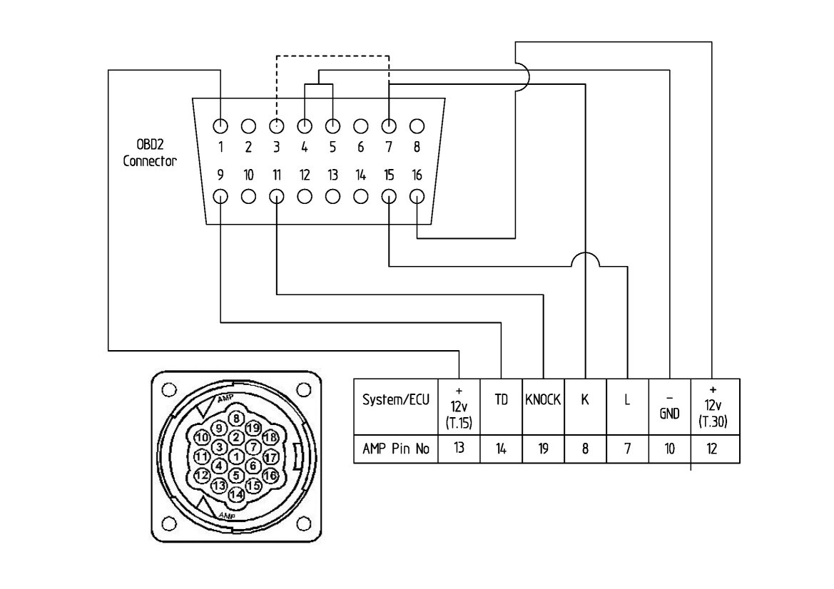
I have seen one of those with all pins populated, and it was rubbish. The connections were TOTALLY wrong and there was no chance of it working. The plugs are moulded on, so you would have to destroy it to get it apart. I suggest you cut the cable and splice the correct wires together.
Where are you located, that the shipping was more expensive than the part?
Yes, I was going to cut the wires, and connect the correct wires accoridng to your diagram, and then dremel out the unwated pins. I'm located in Singapore.
Thanks for the help!!
-
I know he has used it on a PST2 and it is OK. As Loren says, the PIWIS uses the older PST2 software for the earlier cars, so I think it would work.
The Knock wire is for knock detection, and the TD connection for engine speed. I don't think the PIWIS would use these signals though.
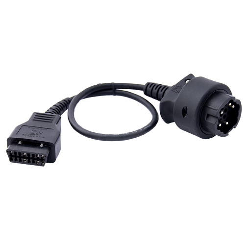
Where are you getting the 19-pin plug from? Do you have a link?
Sensolutions has one here:
But shipping was excessive to my country. So in the end I went with a 16pin to 19pin adapter from ebay (china) like mentioned by Porschelibrarian, that may or may not work, and when I have it in hand I'm going to dissect it and wire it according to your diagram. It is fully pinned, all 19 pins, so I will attempt to remove the extra ones. I am not comfortable having all the pins connected even though they are not needed!
A search on ebay will turn up quite a few of these adapters.
-
Perhaps I am confusing you. When I refer to an adapter cable, I mean one like the Sensolutions/Durametric one, which converts the OBD2 cable into a 19-pin cable. This has an OBD2 Socket on one end, and a 19-pin plug on the other.

I dug out my notes, and here is the schematic I used for the adapter/converter lead:
Note that the 19-pin diagram is a view looking at the socket. The dotted line between pins 3 and 7 of the OBD2 plug is to join two K-line connections. In both my PST2 and PIWIS cables there is already a wire joining these two connections, so I had no need to put it in my adapter cable. I guess I should add that you try it at your own risk, but it worked for me.
Edit: The PIWIS instructions list: "Diagnostics adapter cable for diagnostics lines with round plug socket" Part number: 000 721 971 81
Edit 2: I remembered that a friend of mine has a Sensolutions adapter, so I got him to check the connections. It is wired the same as my schematic, except that the Knock and TD (engine speed) wires are not connected. All the important diagnosis ones are though.
Fantastic info, just what I needed! Thanks Richard.
I have a 19 pin round connector on order and will be attempting this shortly.
I did consider the Sensolutions cable but when ordering, the shipping was more than the cable itself. Not that the small amount of money is a problem, I wasn't assured if it was the right cable in the first place. It was helpful that your friend managed to check out the connections on his Sensolutions cable. Would you know if he has ever tried it with a PIWIS?
What do the Knock and TD connections do, and would the PIWIS be able to use them?
bleeding air in radiator
in 986 Series (Boxster, Boxster S)
Posted
Noticed something interesting on my car. When it is hot, the valve is "up" by itself, even though the metal wire is in the down position. Is this normal?
Lately, my car has been running hotter than normal, so I was wondering if the bleeder valve is abnormal and has something to do with it.