Welcome to RennTech.org Community, Guest
There are many great features available to you once you register at RennTech.org
You are free to view posts here, but you must log in to reply to existing posts, or to start your own new topic. Like most online communities, there are costs involved to maintain a site like this - so we encourage our members to donate. All donations go to the costs operating and maintaining this site. We prefer that guests take part in our community and we offer a lot in return to those willing to join our corner of the Porsche world. This site is 99 percent member supported (less than 1 percent comes from advertising) - so please consider an annual donation to keep this site running.
Here are some of the features available - once you register at RennTech.org
- View Classified Ads
- DIY Tutorials
- Porsche TSB Listings (limited)
- VIN Decoder
- Special Offers
-
OBD II P-Codes - Paint Codes
- Registry
- Videos System
- View Reviews
- and get rid of this welcome message
It takes just a few minutes to register, and it's FREE
Contributing Members also get these additional benefits:
(you become a Contributing Member by donating money to the operation of this site)
- No ads - advertisements are removed
- Access the Contributors Only Forum
- Contributing Members Only Downloads
- Send attachments with PMs
- All image/file storage limits are substantially increased for all Contributing Members
- Option Codes Lookup
- VIN Option Lookups (limited)


vmimarine
-
Posts
11 -
Joined
-
Last visited
Content Type
Profiles
Events
Forums
External Paint Colors
Downloads
Tutorials
Links Directory
Collections
Store
Everything posted by vmimarine
-
Direct Bypass of HiFi Amp
vmimarine replied to vmimarine's topic in 996 Series (Carrera, Carrera 4, Carrera 4S, Targa)
This is the same issue I ran into. The DSP controller is resident in the PCM in this setup. There is a separate wake up signal AND a data signal that are needed for the DSP to function. Unfortunately, there is no way to "convince" the amp that the DSP controller is in the loop and thus the amp won't produce sound due to the fault condition. I have not not found a way to avoid replacing the amp with an aftermarket solution. My project is on hold until till then. -
Direct Bypass of HiFi Amp
vmimarine replied to vmimarine's topic in 996 Series (Carrera, Carrera 4, Carrera 4S, Targa)
Well, experiment finished and suspicion confirmed. No sound signal is allowed through the amplifier with the DSP not in the loop regardless of whether it is turned on or off (powered or not). So the M680 is indeed incompatible with an aftermarket amp when controlled through the PCM1. Seeing no easy way to direct wire past the amp, it would seem that I am going shopping for an amp. Is the impedance of all of the installed speakers 2 Ohm? -
Direct Bypass of HiFi Amp
vmimarine replied to vmimarine's topic in 996 Series (Carrera, Carrera 4, Carrera 4S, Targa)
So I called the audio installer (purchased an installation item from there that I will post as I go too) where I saw this note: "PCM (factory double DIN) equipped vehicles with DSP of all years require a replacement amplifier when upgrading the radio. The factory DSP amplifier is not compatible with aftermarket radios. You can identify a DSP equipped vehicle by looking at the amplifier in the trunk. It will have DSP written on it." So after talking to him,referencing a pinout listed in another forum post here about a PMC1 to CDR220 swap and a post about upgrading to an M680 amp, and then pondering the issue some more, I think I have arrived at: 1. The DSP "controller" in my setup is the PCM1. (intuitive I suppose based on the PCM1 DSP Options) 2. The PCM communicates with the DSP amp through PINS 6 & 14 on Plug II: "DSP Ground" (-) and "DSP Amplifier" (I assume data not 12V+) respectively. 3. Unless the DSP controller is in the loop, the amp potentially will not pass through a signal. So I am wondering if the PCM requires power to support the data loop. In other words, if I turn the DSP off before I disconnect power from the PCM, will I get a pass through signal on the amp? Doubtful I think, but I suppose it's time for an experiment because...why not? I'll let you know how it goes. -
Direct Bypass of HiFi Amp
vmimarine replied to vmimarine's topic in 996 Series (Carrera, Carrera 4, Carrera 4S, Targa)
With any luck I can give it a shot this weekend and see how it goes. Regardless I am going to disable DSP on the PCM before I unplug everything. I'll let you know how it goes. Really appreciate the input. Thank you. -
Direct Bypass of HiFi Amp
vmimarine replied to vmimarine's topic in 996 Series (Carrera, Carrera 4, Carrera 4S, Targa)
M680 is definitely on the sticker in the boot, and I have access to DSP options (that do affect the audio playback) via the PCM1. However, there is definitely not the control panel in the passenger compartment you are talking about. -
Direct Bypass of HiFi Amp
vmimarine replied to vmimarine's topic in 996 Series (Carrera, Carrera 4, Carrera 4S, Targa)
Thanks Richard. I appreciate the response. For the sake of clarity, I have a 2000 C4 Cab Tip with M490 and M680 installed. From an interior view, there is just the PCM with the tape deck and the Nav disk unit below. A/C controls are already located on the bottom due to the PCM and Nav consumption of real estate. I have not started disassembling anything. If I can retain and use the factory amp for the time being, that is fantastic, maybe not for sound quality, but certainly for time, money, and personal preference reasons. My current plan is to leave the PCM1 in place, and put a single-DIN unit in place of the NAV controller (upper slot on lower console). I purchased the unit (Pioneer DEH-X8800BHS) from Crutchfield and it has been shipped with a Metra 70-1787 harness as well as an antenna adaptor. After perusing the uploaded wiring diagram (borrowed from another thread…appears to be the correct one) and then comparing it to the wiring diagram for the Metra harness (unsure whether it could be posted here as the diagram is a Crutchfield product), in my layman’s point of view it would appear that with some slight modification, the harness should “connect” the radio to the amp in such a way as to function. However, I have read in several places that the amplifier is not compatible with aftermarket head units. The statements have been that generic, so I have no other details as to why at this time. So in light of that, below are my assumptions as to the connections. If you wouldn’t mind giving them a onceover, it would be greatly appreciated. 1. Anti-theft connection will have to be disconnected and permanently insulated once the PCM1 is actually removed. 2. C1 Connector (Yellow)* PIN 1: Rear Left (+) ---> connects to ---> Violet RCA on Red Metra Harness PIN 2: Rear Right (+) ---> connects to ---> Green RCA on Red Metra Harness PIN 3: Ground (-) ---> connects to ---> Black wire on Red Metra Harness PIN 4: Front Left (+) ---> connects to ---> Gray RCA on Red Metra Harness PIN 5: Front Right (+) ---> connects to ---> White RCA on Red Metra Harness PIN 6: 12V+ Switched ---> connects to ---> Blue and white wire on Red Metra Harness 3. A Connector (Black)* PIN 1: Unassigned (normally speedometer but not with M680 installed) PIN 2: Unassigned PIN 3: Unassigned (no phone prep on my car) PIN 4: Terminal 30 (12V+) ---> connects to ---> Red wire on Black Metra Harness PIN 5: Antenna Booster ---> connects to ---> Blue wire on Black Metra Harness PIN 6: Terminal 58d** ---> connects to ---> Orange wire on Black Metra Harness PIN 7: Ignition Lock, Terminal 86s ---> connects to ---> Yellow wire on Black Metra Harness PIN 8: Terminal 31 ((-) Ground) ---> connects to ---> Black Wire on Black Metra Harness *Crutchfield wiring instruction for Metra harness indicates yellow and red wire functions are reversed on my model year. Colors listed above to match correct pinout using that assumption. **Not entirely sure what this is…labeled as illumination on Metra Wiring Diagram Thanks again for the help. Hoping this is all that is necessary for the moment. I drive my car A LOT, and the added features of the new head unit would be most welcome. 996_Group_9_Circuit_Diagrams_Part_1 Radio.pdf -
I have a 2000 C4 (w/ PCM1 and HiFi package (non-Bose and speakers in door)) to which I am starting to do some audio upgrades. While there are many methods with which to attack the problem, I am swapping the head unit first for personal preference. I have read that the current amp will not function with an aftermarket radio, but want to make sure that is indeed the case. In that event, I have contemplated using the Metra harness at the head unit and then just wiring a direct bypass at the amp (in theory, thus simplifying the process of installing an aftermarket amp in the future). Has anyone ever done this, and if so, how?
-
High mile role call
vmimarine replied to violaGT3's topic in 996 Series (Carrera, Carrera 4, Carrera 4S, Targa)
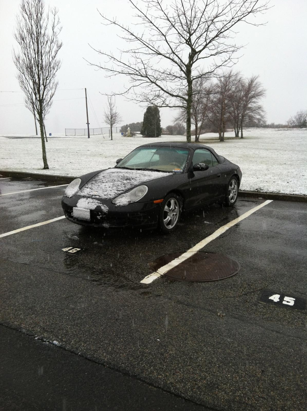
Her name is Ada - 80,600 miles. She currently prowls the roads in NC daily, and runs like new thanks to Robert and his team at Lüfteknic in Richmond, VA! I found her lonely and alone in northern VT on the fast road to the junkyard. Since the beginning of our relationship, she's seen sun, rain, snow, endless highways and byways, and the rutted roads of the eastern seaboard. Looking forward to the road ahead...
-
996 Hardtop
vmimarine replied to vmimarine's topic in 996 Series (Carrera, Carrera 4, Carrera 4S, Targa)
Good to hear. My father is actually picking it up for me as he lives closer to it than I do. His concern was "how" it would sit. For example, will the rear part of the hardtop fit between the front of the bed and the wheel wells so it sits relatively "level". From your reply I would guess that the answer is yes. -
Does anyone know the exact dimensions of a 1999 Carrera Hardtop for the Cabs. Just bought one off of eBay for a great price but need to determine if it will fit easily in the bed of a full size pickup. Specifically interested in overall length, width, and the length from the bottom of the rear window glass to the back of the door window glass (plane to plane). Trying to figure out how/where it will sit in the pickup bed.
-
cell phone charger for 2000 C2
vmimarine replied to moondoggy's topic in 996 Series (Carrera, Carrera 4, Carrera 4S, Targa)
Suncoast Porsche has a cigarette lighter retrofit kit for less than $30. The kit replaces the European-sized receptacle with a US-sized one. The kit took me less than 15 minutes to install in my 2000 C4.