Welcome to RennTech.org Community, Guest
There are many great features available to you once you register at RennTech.org
You are free to view posts here, but you must log in to reply to existing posts, or to start your own new topic. Like most online communities, there are costs involved to maintain a site like this - so we encourage our members to donate. All donations go to the costs operating and maintaining this site. We prefer that guests take part in our community and we offer a lot in return to those willing to join our corner of the Porsche world. This site is 99 percent member supported (less than 1 percent comes from advertising) - so please consider an annual donation to keep this site running.
Here are some of the features available - once you register at RennTech.org
- View Classified Ads
- DIY Tutorials
- Porsche TSB Listings (limited)
- VIN Decoder
- Special Offers
-
OBD II P-Codes - Paint Codes
- Registry
- Videos System
- View Reviews
- and get rid of this welcome message
It takes just a few minutes to register, and it's FREE
Contributing Members also get these additional benefits:
(you become a Contributing Member by donating money to the operation of this site)
- No ads - advertisements are removed
- Access the Contributors Only Forum
- Contributing Members Only Downloads
- Send attachments with PMs
- All image/file storage limits are substantially increased for all Contributing Members
- Option Codes Lookup
- VIN Option Lookups (limited)


KevinH90
-
Posts
254 -
Joined
-
Last visited
Content Type
Profiles
Events
Forums
External Paint Colors
Downloads
Tutorials
Links Directory
Collections
Store
Posts posted by KevinH90
-
-
I need to take some of the pins out of this connector without damaging them:
I'm thinking that a pin extraction tool for a female molex might work, but I would like to be certain before I order a tool. Here are a couple that look promising:
Molex Extractor for Male Female 0 093" 0 062" Pins | eBay
Molex Type Pin Extractor for 093" Size Pins Plunger Type Pin Remover | eBay
I've read some on line reviews of other products and it appears there are some cheap tools out there that break before they can complete the job. I also received a recommendation for an entire kit, but I prefer not to make a big investment at this time.Thanks

-
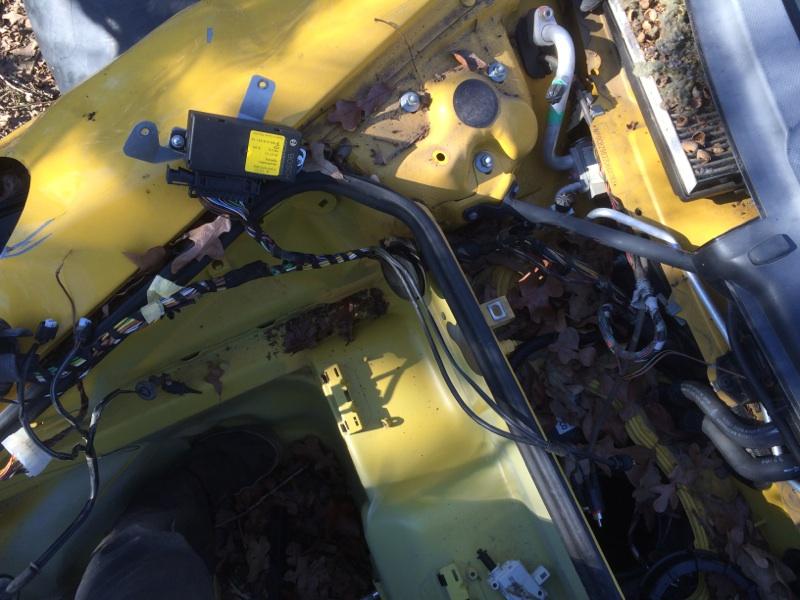
So, I will need to tap into the gray wire at some point after it comes through the firewall. There is are two gray/black wires on the connector pictured in post 47, but I'm assuming those won't do the job.
I cannot find any information that explains why the speed input is needed. I wonder whether you would notice a difference if you drove a factory litronic-equipped car back-to-back with your car. Since you seem to be living happily without it, I will ignore it. I can confirm that the harness I have (removed from a car with factory litronics) has a orange/blue wire in pin 9, gray wire in pin 10 and a white/brown wire in pin 11.
My test plan is to leave my litronics and ecu in the car and hook up the sensors temporarily. I will then vary the relative positions of the two sensors. That way I will be able to see what happens when (1) the front sensor is higher; (2) the rear sensor is higher; and (3) when the sensors are level. I should also be able to observe the start up routine.
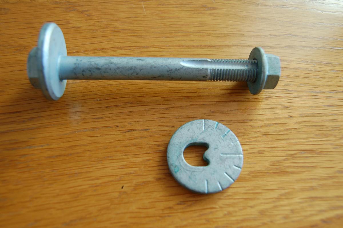
Regarding the washers - I don't have the parts. I need to start planning and budgeting time and money for a top (or as you might say hood) replacement. I normally plan my projects carefully, but the litronic upgrade was done on impulse when I spotted someone selling a damaged pair for a good price. One thing has led to another on this project, but I have limited time and I need to put it to good use. You can read about my litronic project here: http://986forum.com/forums/general-discussions/54697-advice-used-litronics.html
Cheers
-
So, it is the yellow and white wire for the light turn on signal. I won't have any problems hooking into that.
It is also nice to know the ECU's are identical. I won't have to remove the one I have. I'll wait to sell the other one until I'm sure I won't be needing it.
I'm wondering why there is a provision for the engine speed signal if it isn't necessary. Does it affect the amount of headlight rotation. Since it is the engine speed, not the vehicle speed does it rotate the headlights down slightly to compensate for the effect of acceleration and deceleration? The front of the car does point up a little when you are accelerating and down when braking, but the sensors on the suspension should pick that up. Maybe it is a early warning system. If you take your foot of the gas, the car gets ready to correct a downward inclination.
Also, I think the pins in the connector are molex pins. So, I may need a molex pin extractor. http://www.amazon.com/Connector-Remover-Computer-Extractor-Sleeving/dp/B0094MIS9U/ref=sr_1_3?ie=UTF8&qid=1423950285&sr=8-3&keywords=molex+pin++and+removal+tool
-
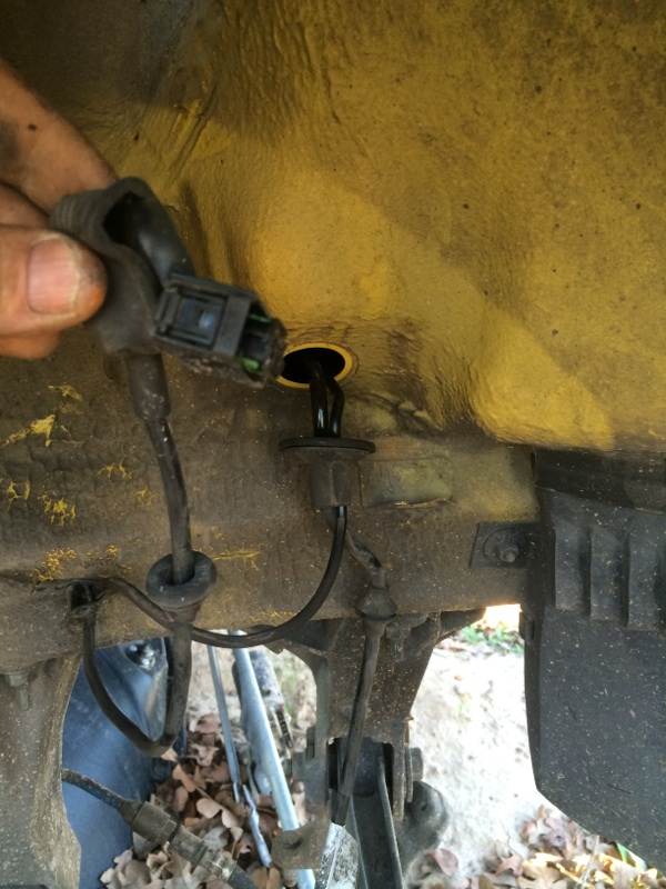
I think you may have saved me some head scratching. If I don't find a way to tell the system that the headlights are on, the system would be dead in the water.
So, it looks like I have two options for telling the system to turn on:
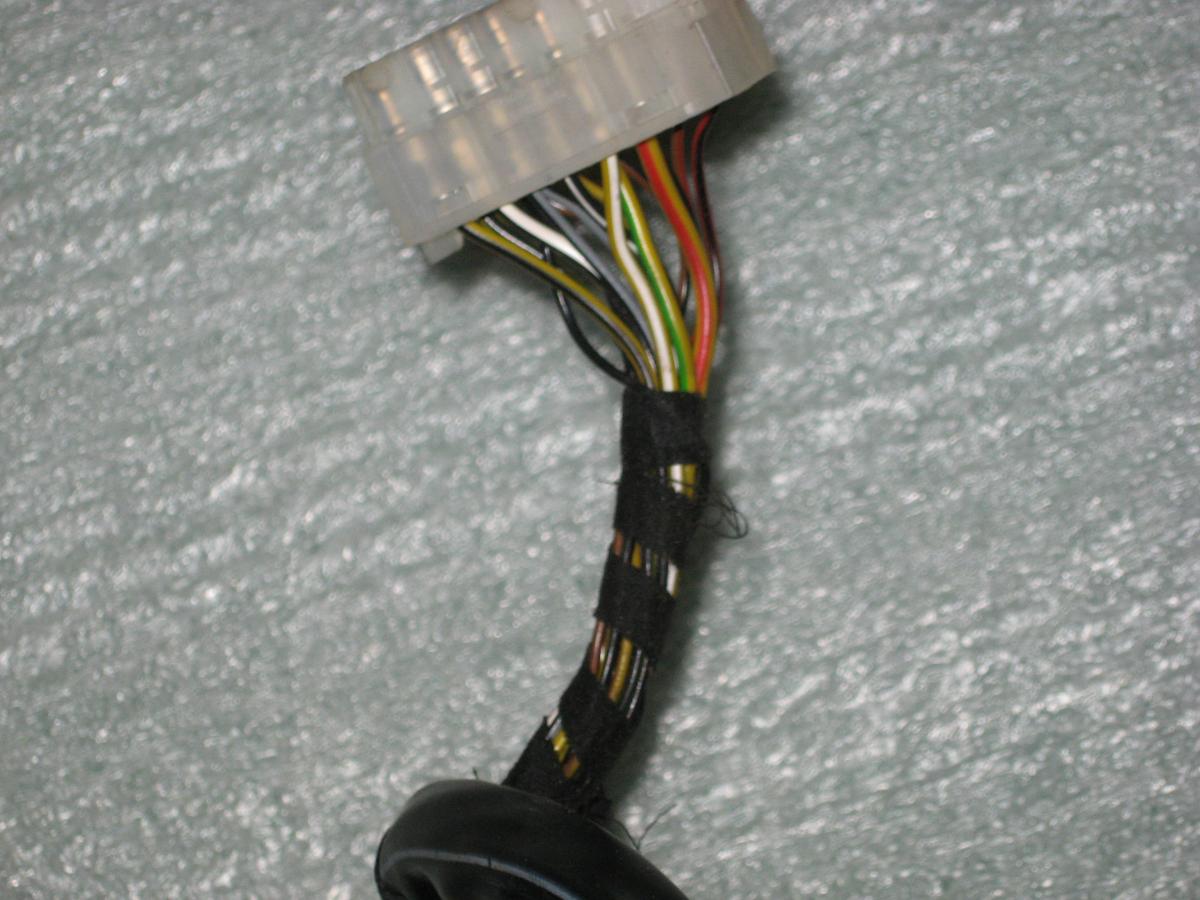
1. Trace the gray wire from the back of the cluster and connect it to pin 10.
2. Tap into the connector that I used for the high beam on signal for the retrofit kit and connect that to pin 10. I have attached a photo of the connector. It appears that the yellow/white wire is the one to use.
Regarding the ESO/Pin 11
It appears that I will need to access the ECU in the rear trunk or find some other location to pick up the Engine Speed Output Signal. If I recall correctly, when I installed the Navigation unit in my dash, there was a speed signal in that loom. I'll need to check if that is a better option. I have a 2000 Boxster and the only wiring diagrams in it are for 1998 and 2001 models. However, it appears that I have the DME 7.2 and that there is a "Speed signal output" on pin 17 of the 40-pin connector D.
That still leaves Pin 9 unused, but it appears I could hook that up to the diagnostic plug under the steering wheel and hope for the best.
Thanks for the pointers. I'll keep puzzling this out.
-
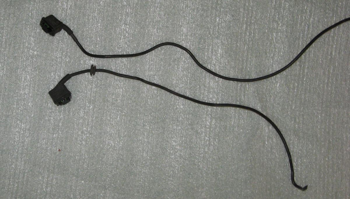
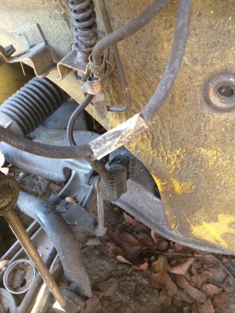
I received some of my parts today. The sensors and brackets will probably arrive next week. Since I like to plan as much as I can and anticipate challenges, I'm going to start asking questions (see the bold items) even though the earliest I can start the installation is about 2 weeks from now.
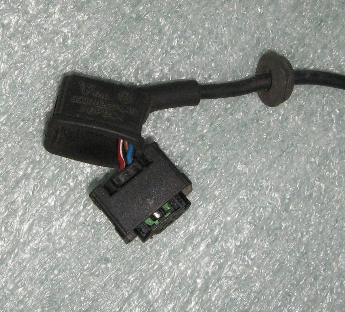
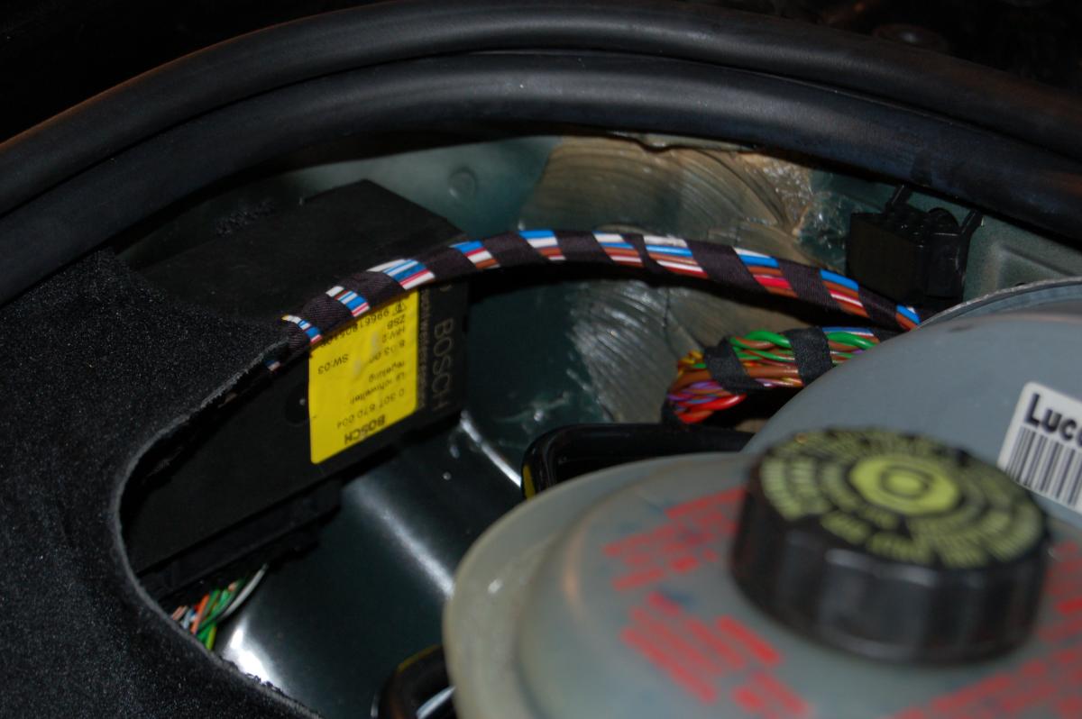
The first photo shows what I'm assuming to be the connectors that fit on the sensors. The second photo shows a close up of the connector with the red/white, blue and brown/black wires. This configuration matches the wiring diagram in my Bentley manual.
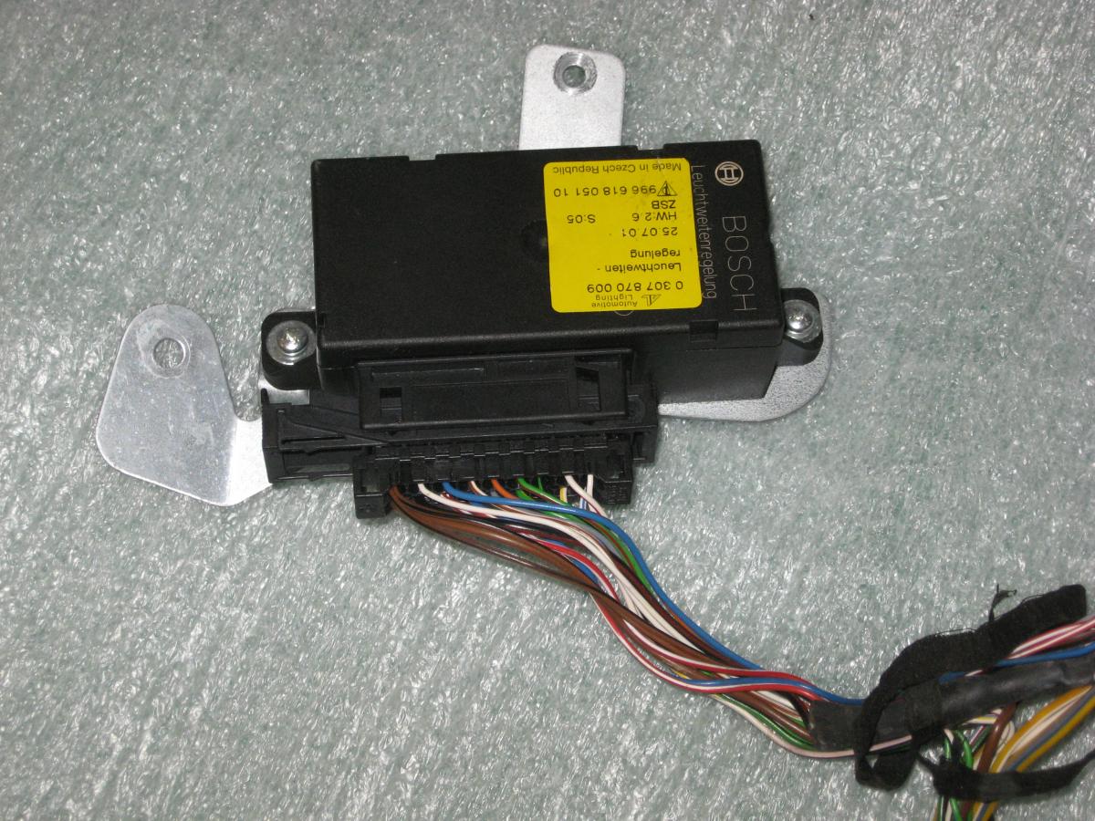
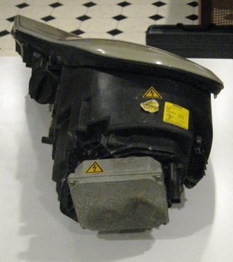
The third photo shows the control module and 18 pin connector. I think the connector is identical to the one I used in the retrofit kit. I cannot be certain that the control module is the same, so I'm going to have to test to be sure. I have both types available and I'll eventually sell the one I don't need.
The fourth photo shows the pins in the connector. Pins 1-8 are for the wires that run to the connectors on the back of the litronic headlights. They activate the drives in the unit. I'm planning to use the connector I installed with the retrofit kit since it is already in the car and I know that it works. I will then remove pins 12, 13, 14 and 17 from the harness in the picture and use them as part of the wiring loom that connects to the sensors. Does anyone know which type of pin removal tool I need to remove the pins?
Here's the pin assignment in the connector based on my research in the Bentley manual and my experience installing the retrofit kit.
Pins 1-8 As mentioned above pins 1-8 go to the litronic drives in the headlights.
Pin 9 - Diagnostic (Blue/Orange) Not used because of the risk of throwing codes
Pin 10 - Signal on light (Gray) This looks like it runs to the cluster terminal 58, but I'm not sure what it is for
Pin 11 - ESO (Engine Speed Output) (White/Brown) This appears to run to CP (Connecting Point) 88
Pin 12 - Front sensor (Blue)
Pin 13 - Rear sensor (Blue)
Pin 14 - +5V power supply to both sensors (Red/White)
Pin 15 - Signal on high beam (White) - I already tapped this for the retrofit kit
Pin 16 - Power (Red/Black) - I already tapped this for the retrofit
Pin 17 - Ground to both sensors (Brown/Black)
Pin 18 - Ground (Brown) - Already done for the retrofit
So, right now, it looks like I am not going to be using pins 9, 10 and 11.
Everything else looks pretty straight forward. When I receive my sensors, I plan to connect them as described above and test the system before I install the sensors on the car.
All feed back and suggestions are welcome.
Thanks in advance.
-
Thanks JFP
Duffy - I may need the pin extraction tool to remove the wiring harness I installed to activate the low beam rotation function. The connectors on the back of the headlights are too big to fit through the holes in the side of the trunk. If the harness I receive from the breaker works OK, I'd like sell the one I have to recoup my funds.
I should receive the harness on Friday or Saturday, so I'll post some pictures this weekend. It may be several weeks before I have time to crawl under the car and actually perform the installation. So, please check back from time to time in case I am in desperate need of advice.
-
Thanks for the reply.
Right now, I would have trouble telling the front sensor from the rear one, but I understand what you mean about it being obvious when you have the parts in hand. However, I may have more obvious questions when I start working on the project.
I think one of the reasons very few people have tried this is that there are many posts on the Internet saying it cannot be done. I think you are the first person to indicate a successful outcome. Also, the pictures you posted were helpful in explaining to the part sellers what I needed. I'm not sure that they would have identified them so easily without the visual information.
I'm tempted to connect it to the diagnostic system and see if I can test it with my Durametric. I'll need to think about that before I do it.
-
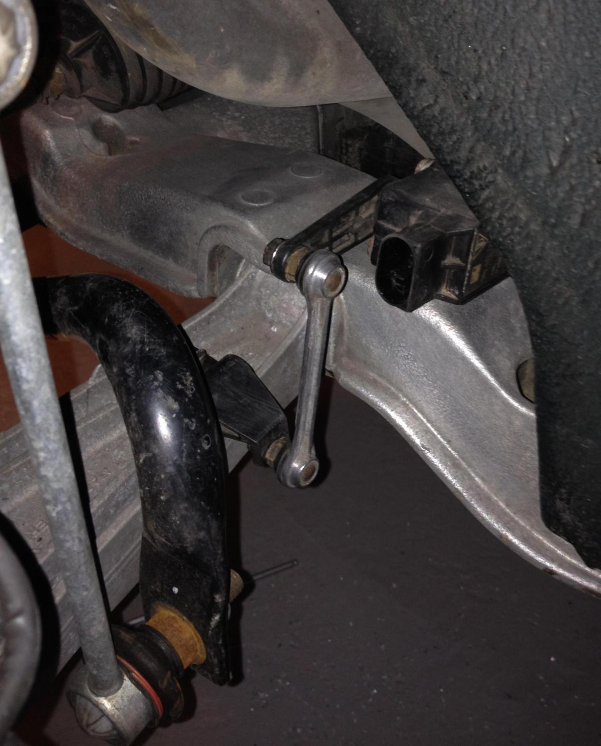
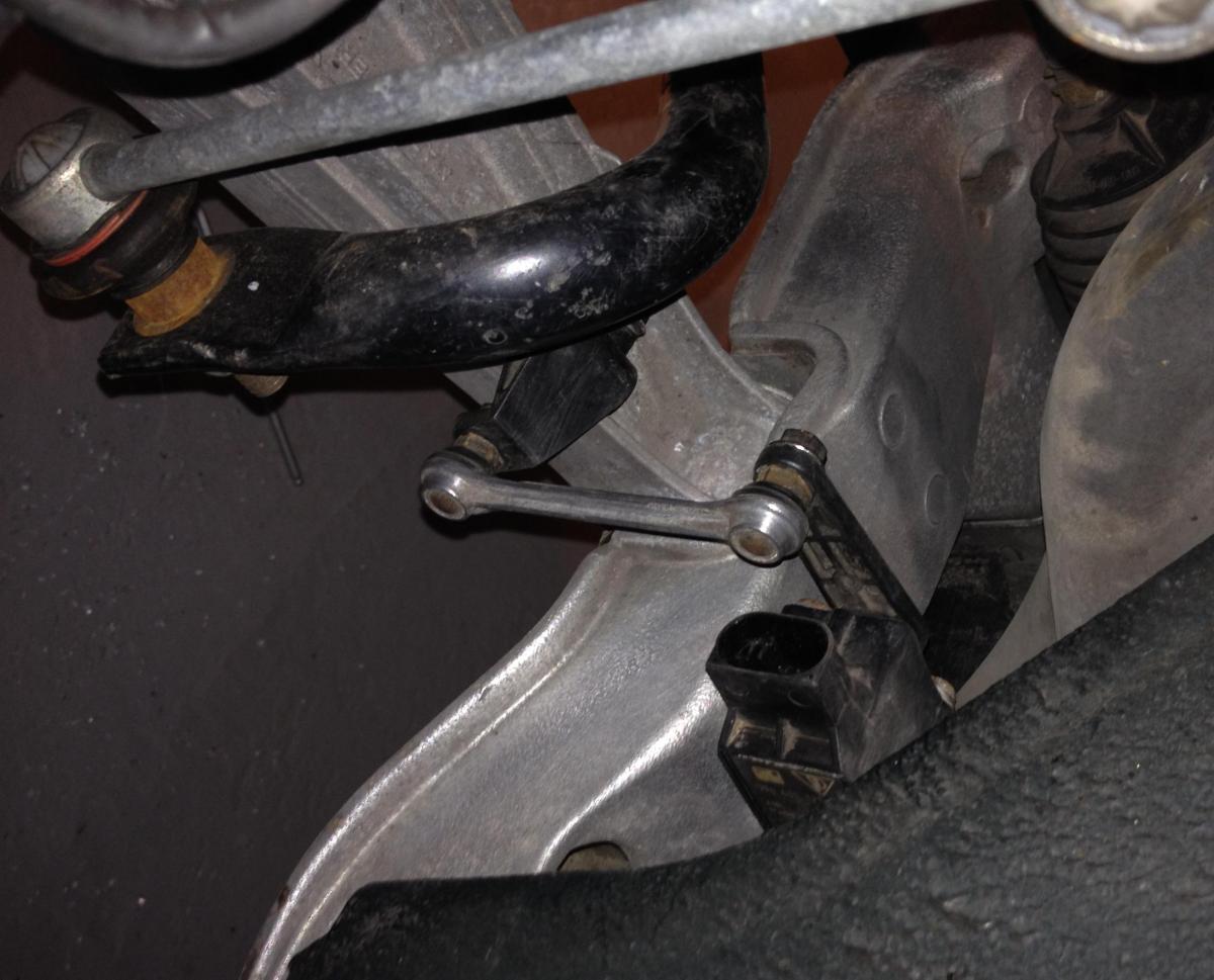
I managed to find a source for for the automatic dynamic headlight beam adjustment (ADHBA) system components. I'm buying them from a couple of gentlemen who are parting out cars. I'm going to attempt to install the fully functioning system in a few weeks after the parts arrive and I have some time to check out the components and plan the installation.
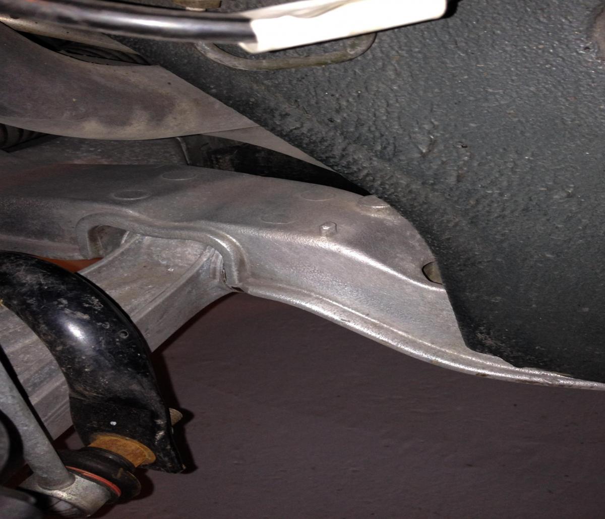
I reviewed Duffy3074's posting on Boxtanet and it helps. The part sellers also sent some pictures of the components as they removed them. I've posted them here. I would appreciate assistance with some of the details including precise guidance on positioning and orienting the sensors. For example, are the mounting holes already drilled or will I need to locate and drill the holes.
It will probably be easier to figure out once I have all the parts, but I would like to start thinking this through right now.
Also, since I already have the high-beam rotation feature, I may have the control module and wiring harness from the retrofit kit for sale if anyone is interested. I was wondering if there is a tool that can be used to help remove the connectors from the plugs that fit into the sockets on the lights. JFP an Steve discussed putting them on one of the threads. I may want to take them out.
Like I said, any help, suggestions or photos will be eagerly reviewed.
-
When I was working on my project, some folks recommended North Hollywood Speedometer and Palo Alto Speedometer as being the experts for repairing VDO gauges - the brand found in our cars. You may want to see if they have encountered your issue before and see if they can suggest a repair. I've heard that replacement parts for the Porsche VDO gauges are not available, but perhaps they have a source.
Good luck.
-
I posted instructions for programming the cluster here: http://www.renntech.org/forums/tutorials/article/377-programming-a-carrera-instrument-cluster-for-transplant-to-a-boxster/
If you damaged one of the components in your cluster, you should be able to reprogram the circuit board from a 986 or 996 to work in your cluster.
-
That is exactly what I was looking for.
Thanks
-
Sorry to dredge up an old thread, but this is intriguing.
I just finished assembling a set of litronic headlights and a retrofit control unit from various sources. After some repairs and restoration of the headlight covers, I have a nice looking set of litronics with the high beam raise function operational. You can read about it here:
http://986forum.com/forums/general-discussions/54697-advice-used-litronics.html
and here:
http://986forum.com/forums/general-discussions/55119-986-litronics-plug-play.html
if you are interested.
Rather than quit while I'm ahead, I'm intrigued by the prospect of adding the dynamic leveling function. I have found a pair of the sensors, but before I spend the money, I was wondering whether you have any additional information including a step-by-step write up and a final decision on whether connecting it to the DME is a viable option.
Thanks,
-
The information in that DIY document was developed by an electronics hobbyist and is not standard Porsche technical service bulletin information. You can read more about how this was developed on the 986 Forum:
http://986forum.com/forums/general-discussions/43017-carrera-gauge-swap.html
and another thread showing a cluster similar to yours' here: http://986forum.com/forums/general-discussions/52581-996-c4s-cluster-install.html
Unless you run into a particularly adventurous Porsche technician, I don't think a dealership will do this for you.
You need to either:
1. Take the plunge and purchase the equipment to do it yourself - several folks on the 986 Forum did, or
2. Find an electronics shop that can program an EPROM (Erasable Programmable Memory) chip.
I see that you are in Dubai, so I'm not sure what resources are available to you. Maybe a computer repair shop can help you.
I think it can be done, but you just need to find the right person.
Cheers,
-
Here's a link to instructions for programming a 996 cluster. http://www.renntech.org/forums/tutorials/article/377-programming-a-carrera-instrument-cluster-for-transplant-to-a-boxster/
While these instructions were specifically written for coding a 996 cluster to work in a 986, they discuss the inner workings of the cluster program.
I don't claim to be an expert on this, but I suspect that the Porsche service tool that your dealer is using cannot access all of the code that needs to be changed. Although it is not something the dealer would be willing to do, you could copy the code from your cluster to the new cluster and see if it would work. The instructions in the link tell you how to do it. If you can find someone in your area with experience programming an EPROM chip, you should be able to get it to work unless the cluster is defective.
Good luck.
-
Programming a Carrera Instrument Cluster for Transplant to a Boxster
Working with the EPROM on Porsche Boxster - illustrated - old and new style clusters(1)-1.pdf Working with the EPROM on Porsche Boxster - illustrated - old and new style clusters(1)-1.pdf
-
Author
-
Category
-
Submitted12/31/2014 08:24 PM
-
-
I was able to get this done. If anyone wants the full details, you can read them here: http://986forum.com/forums/general-discussions/54697-advice-used-litronics.html
Basically, I found another used light with a bad wiring harness and swapped the parts to make one good headlight. Looks good and works well.
-
Here's a post on swapping the 6-channel amp for the 4 channel. They used the Haes amp, but the Nokia may be similar. I used this post when I made the swap on my 2000 Boxster. I expect it is similar for a 97.
http://www.renntech.org/forums/topic/3389-pinout-for-6x40-m490-amp/
-
I bought a set of used litronics that I knew were not in very good shape. My plan is to refurbish them if possible and install them on my 2000 Boxster.
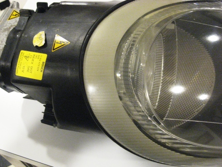
The passenger-side headlight appears to be in decent shape. I'm planning to use the Sylvania headlight restoration kit on it to take the discoloration off the outside of the lens and just clean it up. I'll check to be sure it works before I expend the elbow grease. Here are some pictures:
You can see the oxidation at the top of the lens here:
The driver-side headlight is a little rougher. The lens needs more restoration than the passenger lens:
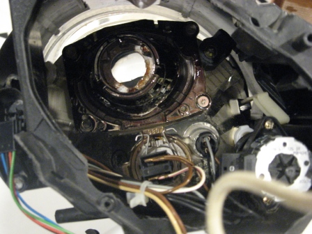
The more significant problem is that the back side is broken and many of the internal components are rattling around loose. The litronic bulb (D2S) is broken and the reflector behind it just slides around:
Does anyone have experience with repairing the internal components of a litronic headlight? Can you suggest how to fix this? For example, should I consider heating the unit and removing the lens so that I can work inside the bucket? Can I use the bucket from a non-litronic lens and fit the litronic components inside.
Would it be better for me to find another driver-side lens and just use the components in this one for spares?
If anyone has a litronic with a broke lens to sell and everything else is intact, I'd be interested.
-
Thanks for the responses. I may have more questions after I receive the lights.
-
I have an offer in on a pair of used litronics. I have done some research, but I'm a bit unsure of how to proceed. Here are my questions:1. If I install them without the control module and wiring harness that comes with the retrofit kit, will they work? It seems that based on my research, the low beams won't swivel up to assist the high beams.2. If one of the projectors is loose, can it be repaired? I haven't found anyone who says they can, but it appears you can take them apart with a little heat, so if the price is right I'm wondering if it is worth a try.Thanks in advance for any tips or suggestions.
-
The clusters can definitely be reprogrammed. Here is some general information about how to do it:
http://986forum.com/forums/general-discussions/43017-carrera-gauge-swap.html
Send me a PM with your e-mail address and I can e-mail complete instructions.
-
The problem turned out to be flywheel related. While they have the transmission out, in addition to the flywheel I will have them replace the AOS, Rear main seal (it's leaking), a cracked oil filler tube and the clutch. There are also a few other transmission-related items that need repair.
-
I took my 2000 Boxster (2.7L MT, 91,000 miles) to a shop on Thursday. I had heard a noise from the engine area or perhaps the passenger side rear axle. The car definitely seemed louder than normal, but that is a somewhat subjective evaluation. (I had replaced the water pump last fall, and it did not sound like the water pump failing.)
The shop owner seems to think it is either dual mass flywheel or the IMS beginning to fail. He will be taking it apart to find out.
I did see that there was a TSB on the DM flywheel,
Based on the searches I've done, if it is the IMS it sounds like most folks are favoring the LN ceramic bearing. I think it is likely that I have a dual row IMS (production date of the car was September 11, 1999), but he can verify that when he takes the car apart.
While he's working, I'll have him replace the clutch and the AOS since I've been getting a little smoke lately.
Any suggestions or comments are appreciated.
-
I've searched here and on the 986 Forum and cannot find an answer.Last year I installed an 04 top and frame on my 00 Boxster. My drive to work includes a portion of heavily patched highway and when I go over a bump the passenger side window rattles loudly.I've run my finger between the top seal and the window, and the passenger side is definitely not as tight as the driver's side. I think the window rattles because the weather strip or weather seal is not tight enough against the window.Does anyone have a suggestion for tightening the fit? Is it possible that I didn't align the top correctly when I installed it?Thanks
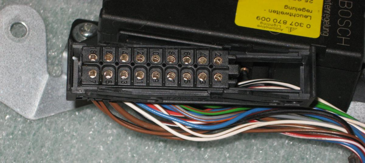


What is the best tool for removing pins from this connector?
in 986 Series (Boxster, Boxster S)
Posted · Edited by KevinH90
Thanks for the suggestion. Unfortunately, there is not an obvious way to take it apart.
There is a sliding component that locks the connector onto the ECU for the litronic headlights. You can probably see it better in this view. I'm pretty sure I can pop that off, but I don't want to break it. Maybe that will expose more of the connector and I can see some way to take it apart.
Also, I'm wondering if this might be the female pin that they use:
http://www.repairconnector.com/deutsch-female-open-barrel-replacement-terminal-16-18-ga-5-pack/
If it is, I could connect my wiring to it and just insert it in the connector that is already in the care.