Welcome to RennTech.org Community, Guest
There are many great features available to you once you register at RennTech.org
You are free to view posts here, but you must log in to reply to existing posts, or to start your own new topic. Like most online communities, there are costs involved to maintain a site like this - so we encourage our members to donate. All donations go to the costs operating and maintaining this site. We prefer that guests take part in our community and we offer a lot in return to those willing to join our corner of the Porsche world. This site is 99 percent member supported (less than 1 percent comes from advertising) - so please consider an annual donation to keep this site running.
Here are some of the features available - once you register at RennTech.org
- View Classified Ads
- DIY Tutorials
- Porsche TSB Listings (limited)
- VIN Decoder
- Special Offers
-
OBD II P-Codes - Paint Codes
- Registry
- Videos System
- View Reviews
- and get rid of this welcome message
It takes just a few minutes to register, and it's FREE
Contributing Members also get these additional benefits:
(you become a Contributing Member by donating money to the operation of this site)
- No ads - advertisements are removed
- Access the Contributors Only Forum
- Contributing Members Only Downloads
- Send attachments with PMs
- All image/file storage limits are substantially increased for all Contributing Members
- Option Codes Lookup
- VIN Option Lookups (limited)


996electric
-
Posts
22 -
Joined
-
Last visited
Content Type
Profiles
Events
Forums
External Paint Colors
Downloads
Tutorials
Links Directory
Collections
Store
Posts posted by 996electric
-
-
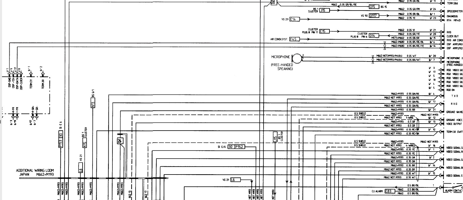
Hi, Im actually changing also my PCM1 with DSP M680 against a aftermarket navigation system / radio.
Originally the amplifier was connected to PCM1 via DSP Data and DSP ground. I have bought now the DSP panel and wired it up according the wiring diagram, but the clock and interrupt line from the amplifier in the trunk are not present (White black and white blue). I guess they should be in the black connector.
Question:
Is the amplifier the same in both situations and only the two cables are missing in the wiring harness?
Is it possibly to get the pins and rewire the wiring harness (I know, not an easy job with the small connector). Or do I have to exchange the amplifier against a M490?

-
-
Hi,
Im searching a connector (which is on the wiring harness of the engine) to connect to the lower X59/1 connector. Does anyone know where to get it?
-
Hi,
in parallel I tried to fine one from the 997 but the only one I can find is from the 996. Maybe I have to search for a longer period, but if anyone would have one it would be very nice to get it. The 997 pedal fit's very good into the position of the 997. That's the reason why I want to go for it.
-
Hi, I want to use the pedal in a 996 to control an inverter. The car will be converted to be electric.
But I need to build a electronic to go with the signal from the accelerator pedal to the controller.
It would be nice to know how it works and which of the pins are for power supply and how the signal looks like which comes out.
-
Ok, but do you have a kind of pinout for it or how it works?
Thanks in advance.
-
Good question, it's a used pedal from a 997 model which will be built in in my 996 electric.
I would guess 2005 911 rear wheel drive, no turbo.
The ebay auction details:
Porsche 911 997 987 Boxster 2008 Fahrpedal Gaspedal Tiptronic 99742302102
-
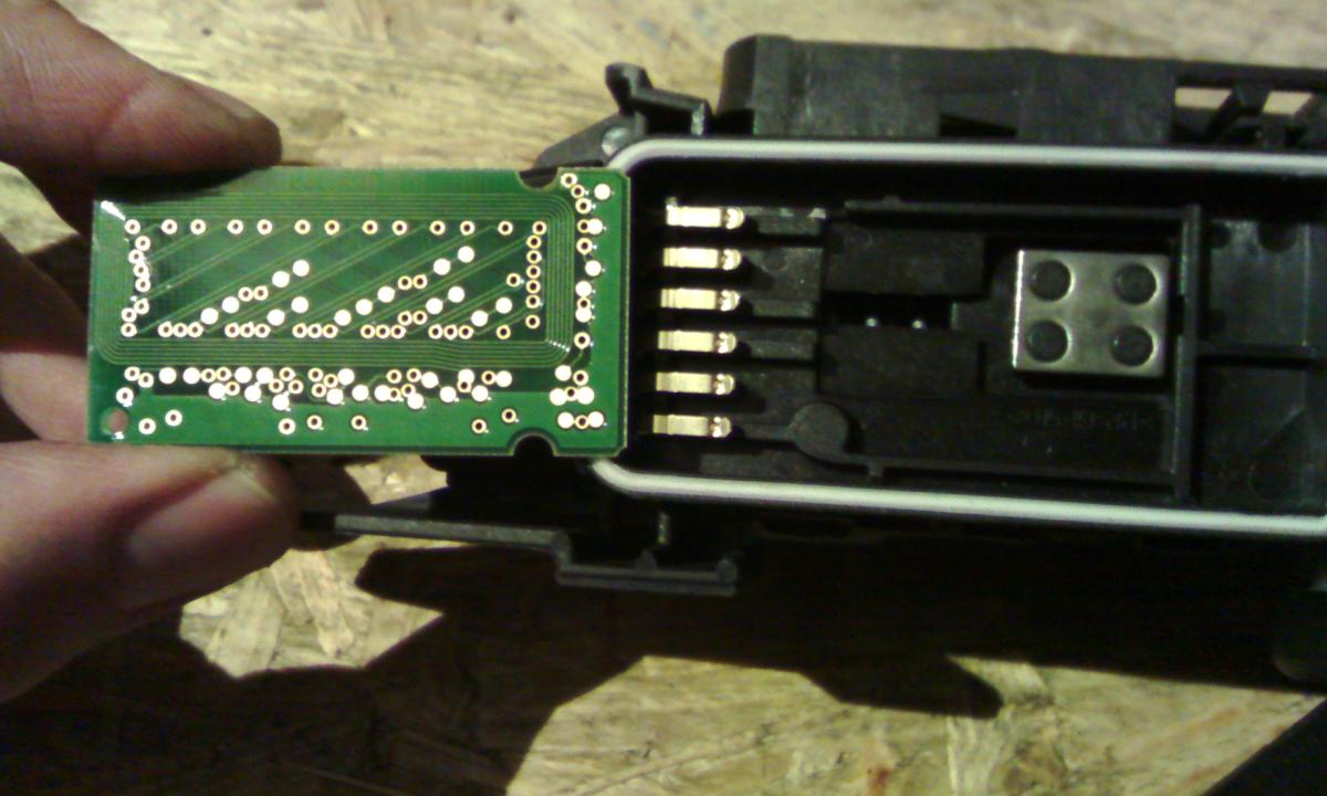
The slider moves over the pcb on the backside.
So this results in an increased number of turns or a decrease of number of turns.
So this could mean a higher or lower restance, but the slider looks like graphit but it does not carry current, it has a high ohmic resistance.
So the other idea could be it is magnetic, but it isn't.
-
A picture of the pcb in the accelerator pedal.
Does anyone have the pinout?
-
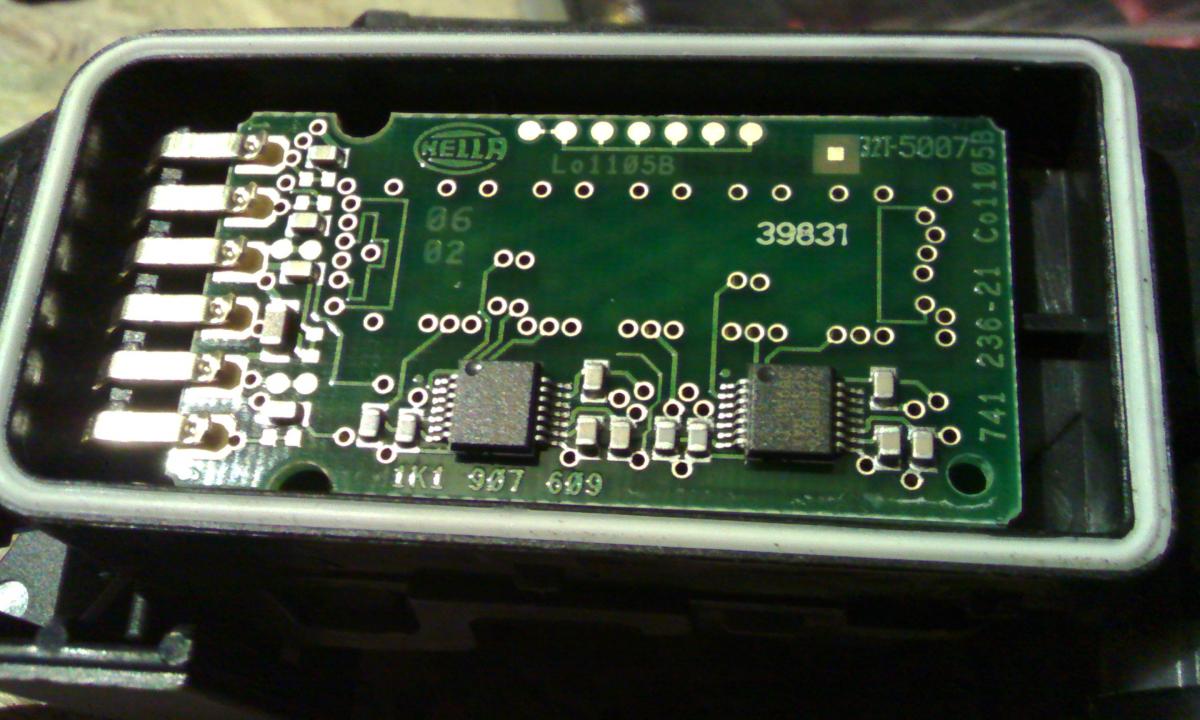
Hi,
Im searching for the pin out of a 997 accelerator pedal. I tried to measure the resistance between the pins, but I did not have a success, all are high ohmic.
One possibility could be that the throttle is a hall effect throttle and not a classic poti.
Does anybody have information about it for me?
-
Correct! But very well protected in the wiring diagram ;) Or let's say I could not find it in it.
-
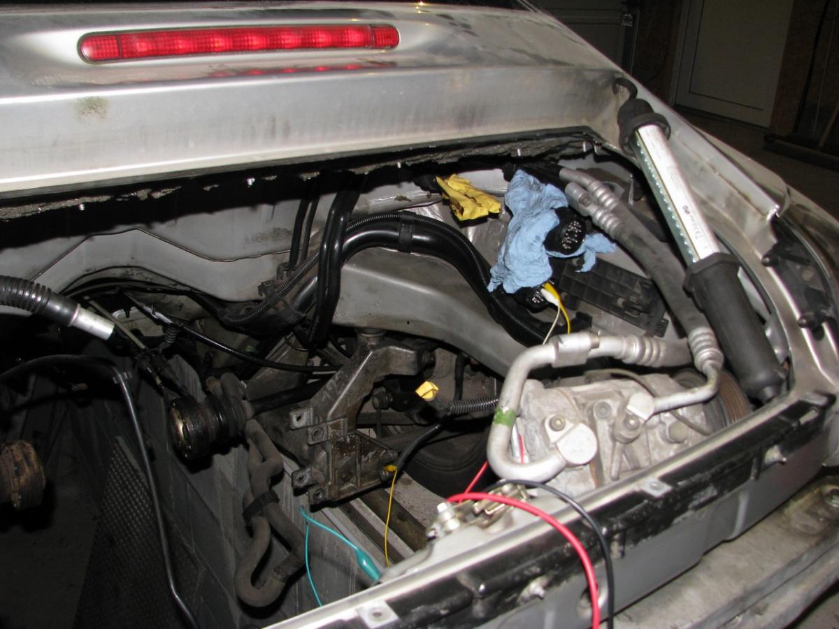
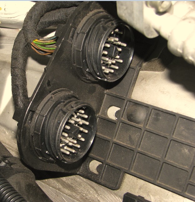
Here is a picture of the engine compartment without engine and investigation about the signals...
-
Very interesting:
Between 16 and 18 is the signal. It has an ohmic range from 5 bar equals 219 Ohm, 0 bar equals 9 Ohm.
So simply connect these two signals together and you'll getting it to work.
-
Ok, I will figure out this afternoon. Do you know where to find analog ground? Some signals are referencing to it which are through the connector X59/2 and separately to analog ground. I guess it is ground of chassis but im not 100% sure. I have to try.
-
And yes it's a fun project. Im driving the BMW now since more than 10000km with great fun, much better than before.
The Porsche will be equivalent than before. Thats enough for me.
-
Yes thats the plan.
A colleague is now working on the signal 60-2,
Im actually figuring out what is necessary for the oil pressure gauge to run.
On Pin 16 and 17 I did not have luck with a poti. I know already the pressure should normally be 19 Ohm when the engine is not running so 0 as value. But it is always going over 5 bar. So it looks like there is an information missing. But I could also read the oil level sensor is independend.
Current situation:
Speedometer - ok
Battery voltage 12V - ok
Oil level measurement - not needed anymore
Oil pressure measurement - could be useful - not working up to now with pin 16 and 17.The range should be 10-180 Ohm, 19 for 0bar..
Engine speed signal - in operation.
-
Is for a correct function of the oil pressure sensor the oil switch connection necessary?
I just put a resistor on pin 16 and 17 and nothing real happened. It should be 19 Ohm without pressure, but it is constantly over 5.
I don't have the engine in the car anymore, so the question is which signal is needed additionally?
-
Did anyone figure out the range of the oil pressure sender?
-
Hi,
the graph is really good, it indicates the 60-2 signal or in this case! You can count 58 spikes and than a gap (the two times gap) and than the signal starts again. The question is how the 911 does this signal...
So I don't have the engine anymore, does anyone have a scope trace about it? I have to program my arduino to simulate this signal.
When I got it right, I can convert simply the engine speed sensor signal to this one and the ECU gets the original signal.
If any other values are needed for the ECU like HFM or throttle position, I have to think how to simulate them.
-
Hi, its a Carrera c2 from year 1998.
I don't have the engine anymore. I could Figure out that the signals are on the bottom connector. When I put a square wave signal in oft about 600 Hz, funny things are happening linke flicking check engine light and random RPM signal.
How dos the crankshaft signal work is it linke 58-2 signal? So like 60 pin square wave and the last two ones flat?
-
Hello,
Im new in this forum and I decided to go to this forum, because I could see lots of technical information and guys who have knowledge of the car, which is not always present in other ones.
Short introduction:
Im actually converting my private 996 to electrical drivetrain. I did this already with my BMW Z3 (which has the same connector as the 911 which is labeled with BMW on it...
But the 911 has two round big connectors in the trung X59/1 and X59/2.
I figured out that the signal should be present at 9(+ signal) and 10 (ground).
But it does not work on both.
Does anybody have a layout, which signal is on which pin of these two connectors and which one is 1 or 2?
Thanks in adavance!
Need Help Converting from PCM1 to CDR220
in 996 TT, 996 TT S, 996 GT2
Posted
996 Radio with M680 DSP (no PCM1) schematic: