Welcome to RennTech.org Community, Guest
There are many great features available to you once you register at RennTech.org
You are free to view posts here, but you must log in to reply to existing posts, or to start your own new topic. Like most online communities, there are costs involved to maintain a site like this - so we encourage our members to subscribe or donate. All subscriptions and donations go to the costs operating and maintaining this site. We prefer that guests take part in our community and we offer a lot in return to those willing to join our corner of the Porsche world. This site is 99 percent member supported (less than 1 percent comes from advertising) - so please consider an annual subscription or donation to keep this site running.
Here are some of the features available - once you subscribe RennTech.org
- View Classified Ads
- DIY Tutorials
- Porsche TSB Listings (limited)
- VIN Decoder
- Special Offers
- Paint Codes
- Registry
- Videos System
- View Reviews
- and get rid of this welcome message
It takes just a few minutes to register, and it's quality Porsche information at a low cost.
Contributing Members also get these additional benefits:
(you become a Contributing Member by subscribing or donating money to the operation of this site)
- No ads - advertisements are removed
- Access the Contributors Only Forum
- Contributing Members Only Downloads
- Send attachments with PMs
- All image/file storage limits are substantially increased for all Contributing Members
- Option Codes Lookup
- VIN Option Lookups (limited)

jporter
-
Posts
97 -
Joined
-
Last visited
Content Type
Profiles
Events
Forums
Exterior Paint Colors
Downloads
Tutorials
Links Directory
Collections
Classifieds
Store
Everything posted by jporter
-

Bad Experience With 2.5l Boxster 97-99 ??
jporter replied to starkle's topic in 986 Series (Boxster, Boxster S)
I have a 98 with 80K. The car is fun to drive and work on. I have had several of the problems listed in this site and they have been relatively easy and inexpensive to fix with the guidance of Mr Toolpants and his gang of merry men. I haven’t noticed any corrosion and the gas mileage seems ok, but it does use the expensive stuff. -
You probably already know this, but the tone adjustments on the CDR210 in my boxster are stored separately for AM, FM, CD and the CD changer – I don’t know if the CDR220 work the same way.
-
Noob Q: check engine light and strange noise
jporter replied to Zip's topic in 986 Series (Boxster, Boxster S)
I would also recommend Autozone or a similar auto parts store since it’s free. If you want your own reader, I purchased a CarChipE/X from Davis to help solve an O2 sensor problem on my 98 Boxster. The cost is slightly more at $150, but it can record several types of data when the car is being driven in addition to reading the codes – speed, rpm, engine temp, O2 sensor values, intake temps, …. It is a small devise, about the size of two matchboxes. You unplug the device from the car and download the data to a PC. The chip came with a serial cable to connect to the PC and also comes with good software for viewing and saving the data. It also does a great job of keeping track of your car when someone else is driving it – I have two adult children who love to drive the car :( -
Horn Problem
jporter replied to natzee's topic in DIY Articles - Boxster (986) - Common Fixes and Repairs
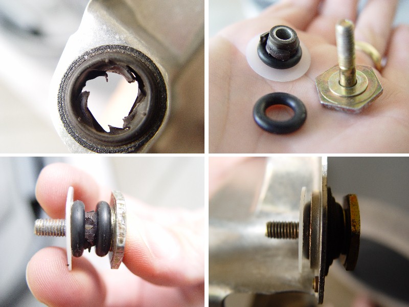
I had some extra time over the weekend so I took some pictures of the fix for the horn covered in the earlier post. The o-rings measured .300 x .580 and .140 thick. The nylon washer measured .375 x .875 and .031 thick. The image below shows the hole after the center is remove, the components partially disassembled, the components together, and the components assembled to the frame.
-
Is there a method for checking clutch wear? My clutch seems to be working fine at this time, I just want to monitor the wear so that I can replace the clutch before the rivets take over for the friction material.
-
Horn Problem
jporter replied to natzee's topic in DIY Articles - Boxster (986) - Common Fixes and Repairs
I had to fix my horn earlier this summer as it was stuck in the on position. This was discovered when I replaced a fuse – the boxster’s horn are loud in a confined area when not expected. The following image shows the basic concept of how I fixed the horn. The o-rings and Washers were purchased at ACE. The o-rings are made of black rubber and I believe are a #38 size – not positive on size number. The washer is made of white nylon and is 3/8 x 7/8. I used the thinner of the two washers that were available in the above diameter. I removed the old center parts of the rubber piece that was in each of the 4 holes since these were about ready to fall out from deterioration. You need to hang onto the old centers as they are used in the fix as shown below. I left as much rubber attached to the frame as possible as this is what holds and locates the frame between the o-rings. I added a nylon washer to provide some extra clearance between the frame and the contact. I had to tack this washer to the nearest o-ring with a small drop of super glue so that they would stay in place during the assembly to the steering wheel. This fix results in a stiffer horn so it is more difficult to toot the horn with you fingers. The horn does work when needed and does not bounce on the contacts.
-
I’m posting the following since it may add a clue to help resolve the problems with the cruise control. My cruise control has not worked since I bought the car earlier this year. The light did go on when I pressed the button, but nothing would happen when I pushed the lever forward. I had not planed on fixing it (since I’d rather drive the car than ride in the car) and was surprised to find it started to work after I changed the air filter yesterday. I also cleaned the engine compartment when I changed the filter – vacuumed and wiped up dust. I may have hit something, but I think the only change was the filter.
-
Intermittent Problems with the roof
jporter replied to npfx's topic in 986 Boxster Convertible Top Issues and Solutions
There are some better sources for help in this site, but here are some comments that could help. These apply to a 98 and I believe are appropriate for other years. As you probably know the top will not operate until, the ignition is on, the parking brake is engaged and the latch is open. There are some other rules like the speedometer signal can’t be greater than 5 km/h – not clear how this would happen if the parking brake is engaged. The most common problems appear to be a defective microswitch in the parking brake, a defective microswitch in the latch and a problem with the relay. These are covered in earlier issues in this site. As a quick check you could try the following. If the windows drop when the latch is opened, the latch switch is probably ok. If the parking brake light goes on when you engage the brake, the parking brake switch is probably ok. This would leave the problem with the relay. Earlier post indicate if you remove the relay and then give it to a dog, an active child or roll it on the floor and plug it back in it works – must be something loose in the relay. Good luck. -
Convertible Top Problem
jporter replied to jporter's topic in 986 Boxster Convertible Top Issues and Solutions
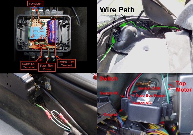
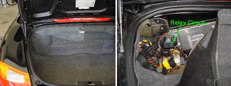
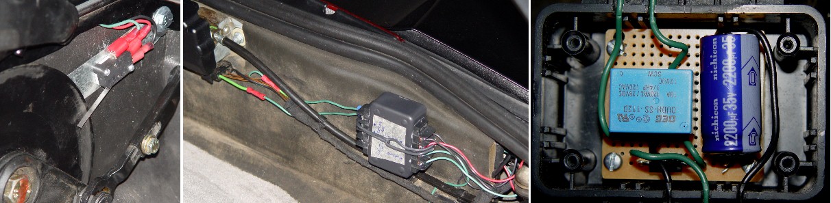
This is the second of 2 posts to describe the fix I’m using for the top issue described earlier. This post will focus on the relay circuit and wiring. The relay circuit was developed to cut the power to the top motor long enough for the “after running” time to elapse and the top indicator light to turn off. At the end of the appropriate time, the power to the motor is restored so that the top can be operated. I used about 2 seconds for the time delay. Although I bought the components at RadioShack, I found similar components at a local electronics store at competitive prices. The circuit is relatively simple with a relay that opens and closes the power line to the top motor, a capacitor stores a charge that is discharged through the coil of the relay at the appropriate time, a diode that prevents the capacitor from discharging back into the car’s system and a resistor to allow the capacitor to discharge when needed. The electrical components are as follows. Relay 12 volts, 10 amps Capcitor 2200 uF electrolytic Resistor 1000 ohms, ¼ watt Diode 50 piv, 6 amps The circuit is shown in an earlier post. The circuit details are shown as an overlay in the following images. The circuit was developed using a breadboard so that the timing could be tested. Note that the capacitor used has polarity and must be oriented as shown. The orientation of the diode is also important. The circuit was assembled/soldered on a circuit board and positioned in a kit box. I glued terminal blocks to the side of the kit box and slotted the sides of the box to allow the internal wires to be attached to the terminal blocks. I also attached a truss bolt to the inside of the box so that it could be attached to the car. The following is a discussion on testing the circuit. The components used will have an impact on the actual delay time. As a result the circuit will have to be tested to determine the actual delay time. The relay makes an audible sound when it opens and closes. When the switch is triggered you should hear a click and then hear a second click about 2 second later. If the delay time is too short, you will need to increase the resistance of the resistor. If the delay time is too long, you will need to decrease the resistance of the resistor. The relay is located in the front left side of the rear trunk as shown in an earlier post. The wires from the switch are tucked under the support frame and then run under the padding to a hole that gives access to the location of the relay. The wires from the top motor run with the top motors wires and are diverted to the relay at the hole referred to earlier. This can be seen in the images below. The relay is inserted in the power line by cutting the green power line to the motor and then attaching the two lines from the relay to the free ends of the power line. This is shown in the image below. I made the cut near the top motor since I originally located the relay in the same area. I would move the cut to an area closer to the new location of the relay since the top motor wires run to an area much closer to the new relay location. The attachment of the wires to the relay is shown in the close up of the relay in the new position. The power to charge the capacitor comes from a wire that is attached to the terminal 15 area of the fuse box in driver side area of the car. I had space available in row E spaces 8, 9 and 10. Although I ran the wire down the center console and under the padding to the hole referred to earlier, I would change this to running the wire through the channel next to the drive side floor board. There may also be a more convenient location for power where the relay is located in the rear trunk. The following is a brief discussion of how the relay circuit and switch operate. When the ignition is on and the CTCL is open the power for the relay circuit flows through a circuit from the fuse box through the diode to capacitor to the Common (COM) terminal of the switch to the Normally Closed (NC) terminal of the switch to the ground of the car. The charging of the capacitor seems to happen almost immediately. When the CTCL is closed (switch triggered) the stored power in the capacitor is discharged through a circuit that flows through the coil of the relay to the Normally Open (NO) terminal of the switch to the COM terminal of the switch and back to the capacitor. Some of the power is also discharged through the resistor. The diode allows the power to flow from the fuse box to the capacitor and keeps the discharge from flowing back into the fuse box. When the capacitor is discharging the power through the coil of the relay, the power is cut to the top motor. It takes about 2 seconds for the capacitor to discharge and as a result the power to the top motor is cut for about 2 seconds. When the capacitor is finished discharging, the power is returned to the top motor.
-
Convertible Top Problem
jporter replied to jporter's topic in 986 Boxster Convertible Top Issues and Solutions
This a reply to Tool Pants post. I have also included larger images for the previous post since they were difficult to read. I will also complete the second post covering the relay circuit and related wiring later today. I spent some time analyzing the top relay and have traced most of the circuit related to the top motor control. I found several possible timing circuits (combination of capacitor and resistor) in this part of the relay. One of the most likely appeared to also control the window drop and I was concerned about the impact of changing this timing. I do believe that I would be able to come up with a way to control the “after running” time with the addition of a variable resistor that could be accessed from the outside of the relay. This will require much more effort/time to develop this solution. You are correct that the current fix I’m using stops the power to the motor sooner than normal (before the “after running” time expires). This will be covered in more detail in the second post on the relay circuit I added to the car. I also believe you are correct that a new relay could solve this problem as the “after running” time may be different. I have not been able to try this since I live in a state with more green and yellow vehicles that run like a deere than cars and more UFO sightings than Porsches. There is also only one Porsche dealer 180 miles away. I will pass on the results when I get a chance to try a new relay.
-
Convertible Top Problem
jporter replied to jporter's topic in 986 Boxster Convertible Top Issues and Solutions
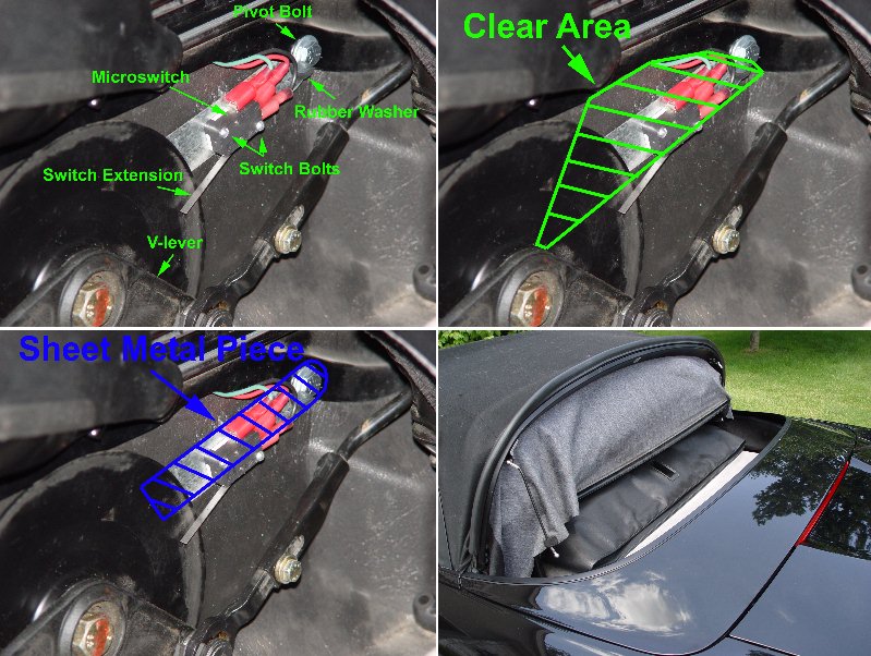
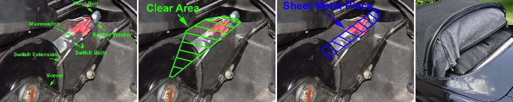
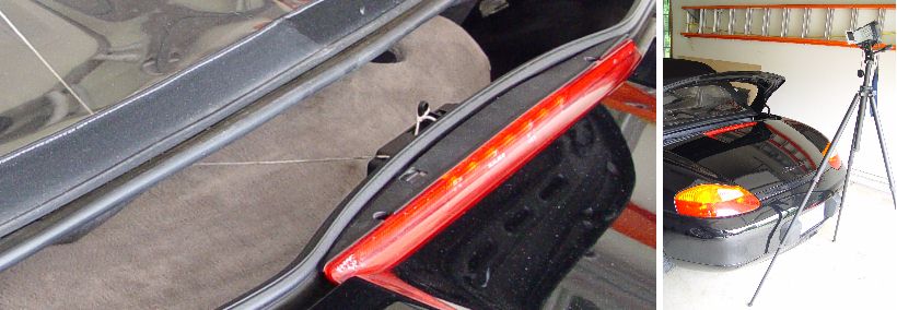
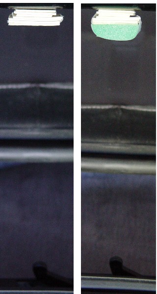
The following posts will be in reply to Alienz request for more details on the fix I’m using for the top issue referred to earlier in this thread. I will require 2 separate posts so that I can include the related images. The 2 posts will be on the microswitch, and the relay circuit and the related wiring. The following will focus on the microswitch. The microswitch was used to provide additional control for the closing of the convertible-top compartment lid (CTCL). I believe the OEM approach of using an “after running time” once the lid switch is tripped is prone to variation due to age, wear, frictional changes and related torque required of the motor. I also believe, although I’m not sure, this was corrected in later models with the integration of a microswitch into the top drive transmission. The microswitch provides a means to stop the CTCL when it is in the proper position. My first thought was to locate the switch so that it would be triggered by the CTCL, but I could not find a location to attach the switch so that the CTCL would contact it a the proper moment, be clear of the moving components and allow for adjustment. I also believe this would not allow for the addition motion of the transmission needed to close the CTCL tightly. I ended up locating the switch at the top transmission because there is an area, indicated in the following image, that is free of moving parts and can be used to trigger the switch when the “V-lever” of the top transmission is in the proper location (CTCL properly closed). The switch has an extension that makes it easier to locate it and was purchased at a local electronics store. The switch is attached to a piece of sheet metal with two small bolts. The piece of sheet metal was cut to a shape that allowed it to be attached to the frame for the CTCL support structure, pivot at the attachment point for adjustment and fit under the shield for the top transmission to hold it in place. The shape was developed by cutting pieces of cardboard until the size and shape worked. The shape is outlined in the following images. The sheet metal is attached to the support frame with the single bolt indicated in the following images. If I were to do this again, I would use a significantly smaller bolt diameter. The bolt is ½ inch long. There are 3 washers with metal washers next to the nut and bolt head. The third washer is a rubber washer located between the piece of sheet metal and the support frame. When the bolt is loosely tightened, the piece of sheet metal can be rotated about the axis of the bolt. This allows you to adjust the location of the switch in relation to the “V-lever”. When the bolt is tightened (not too tight), the location of the switch is held in the proper position. The rubber washer adds additional friction to hold the switch in position. The following is a discussion on adjusting the switch since this section covers the microswitch, but these steps occur after the relay is in place and properly wired. The switch location is adjusted as follows. The top transmission must be timed prior to adjusting the switch since you are only using one side for the control. First unhook the top skirt and cables so that the back section of the top can be pivoted up – this will allow access to the switch when the CTCL is closed (see image below). You will also have to remove the shield on the side of the CTCL. With the back section up, close the top with the switch on the dash until the CTCL is tightly closed. If you go too far and hear the pop, you will have to retime the transmissions and start over. Loosen the bolt and rotate the switch until it is triggered by contact with the “V-lever”. The switch I used made an audible click when it was triggered. Tighten the bolt and partially open and then close the top to check the proper location of the switch. I was lucky enough to have the adjustment work the first time, but suspect you will have to adjust the position based on the trials. The next post will cover the relay circuit and related wiring.
-
Convertible Top Problem
jporter replied to jporter's topic in 986 Boxster Convertible Top Issues and Solutions
I moved the relay circuit for the microswitch to a location behind the trunk liner in the front left corner of the trunk. This keeps it out of the weather and makes it accessible if there is a problem with the top.
-
Convertible Top Problem
jporter replied to jporter's topic in 986 Boxster Convertible Top Issues and Solutions
Hope it works as it would be an improvement to have a simpler solution. I plan to relocate the relay circuit with the other relays up front in the meantime. Although the current solution still works, it would be helpful to access to it if there is a problem and the move would keep it out of the weather. -
Convertible Top Problem
jporter replied to jporter's topic in 986 Boxster Convertible Top Issues and Solutions
I have come up with a solution for the top problem. Although it is not a simple fix, it does work and the total cost for parts was about $25. A mciroswitch senses the location of the left side top transmission. This is used to stop the drive motor for the top. An electrical circuit comprised of a relay and capacitor opens the power line for the motor for about 2 seconds. This is long enough to keep the power off until the “after running time” is over and the top indicator light turns off. The power line is then closed so that the top can be operated. The electrical circuit also includes a resistor and diode to protect the car’s electrical system from a possible discharge of the capacitor. The components are located such that they are out of the way of moving parts and the top when it folds into the compartment. The following images show the components and locations. I will continue to look for a simpler solution and will post it if I find one – this will not be a priority effort since I have a fix that is working.
-
Convertible Top Problem
jporter replied to jporter's topic in 986 Boxster Convertible Top Issues and Solutions
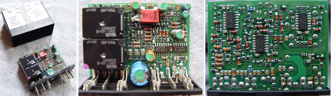
I also looked into modifying the relay to change the “after running” time. The 98 relay is also very complex as shown in the images below. The images show the top and bottom views of the relay out of the case. I plan to show the images to a friend who knows controls. I will post any information I learn about the relay.
-
Convertible Top Problem
jporter replied to jporter's topic in 986 Boxster Convertible Top Issues and Solutions
I had some time to work on the top issue. I measured the “after running” time for the closing and opening cycles. I used a string to trigger the clamshell switch and a camera to record for time measurements – shown below. The “after running” time for closing was normally 1.15 seconds with a couple measurements to 1.20 seconds. The “after running” time for opening was normally 1.00 seconds with some as low as 0.40 seconds. This could be why the opening cycle works. I do not know the reason for the short times, but they could be the result of being near to the point that the B-pillar switch changes. I found that if the clamshell switch was held when opening the top from the closed position that the top stop as soon as the B-pillar switch changed. This also happened when closing the top from the open position. Another reason for the opening cycle working could be the additional load to compress the top at the end of the opening cycle. This could slow the motor and result in less travel at the end of the cycle. I will look into a simple circuit to slow the motor during the closing cycle. I will post the results when I try this.
-
Convertible Top Problem
jporter replied to jporter's topic in 986 Boxster Convertible Top Issues and Solutions
I tried to trip the switch earlier per Mark’s suggestion, but the motor continued to run until the pop sound. The image on the left is the end result of building up the area on the clamshell that contacts the switch lever. The material shown is about the maximum that could fit between the clamshell and the housing of the motor. I monitored this by looking under the skirt of the convertible top – not as exciting as it sounds. The switch was actuated earlier, but the clamshell continued down until it made the sound referred to earlier. I then added the additional foam shown in the image on the right. The foam did actuate the switch upon contact and then compressed when it contacted the housing of the motor. I was surprised that this did not stop the motor early enough to stop the noise at the end of the closing cycle and this could be the result of not having enough room to actuate the switch earlier. Regardless of the outcome I think it could provide a clue to how solve the issue. Thanks again for the idea. My next effort will be to follow Tool Pants suggestion and get a better fix on the location of the noise. This will have to wait until next weekend and I will post the results.
-
Convertible Top Problem
jporter replied to jporter's topic in 986 Boxster Convertible Top Issues and Solutions
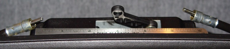
The following should (if I know how to post images) be a picture of the ends of the flexible shafts.
-
Convertible Top Problem
jporter replied to jporter's topic in 986 Boxster Convertible Top Issues and Solutions
I pulled the cables and they are the old style. The square ends extend about ½ inch on both sides. Although they are not as bad as the old cables shown in the other threads, I plan to replace them – better too soon than too late. I’ll keep looking for other reasons for the noise. Hope I get a fix before I break a red ball - sounds like they are in short supply -
Convertible Top Problem
jporter replied to jporter's topic in 986 Boxster Convertible Top Issues and Solutions
The top did not operate when I got the car. The problem was related to the convertible-top lock switch. I believe it was a slightly different problem than the microswitch failure people have discussed here. There are two “conductor bars” (small strips of steel) that are on top of the lock unit. These are visible when the lock unit has been removed. They connect the left side of the lock unit to the microswitch on the right side. When electrically testing the lock unit off the car, I found that it worked every once in awhile. I determined that this was related to how I was holding the lock unit and that’s when I noticed the small break in the solder joint at one end of one of the “conductor bars”. I repaired the joint with new solder and it has worked since then – that’s when I started to hear the noise. Thanks again for the help. I know I have at least ¾ on the right side since this is the side I remove to synchronize the two sides. I will let you know what I find on the other side. -
Convertible Top Problem
jporter replied to jporter's topic in 986 Boxster Convertible Top Issues and Solutions
Thanks everyone for the replies and suggestions. I was out of town yesterday for a meeting. I drove the Boxster and the drive home on the back roads was fantastic – top down, 72 and stars in the sky. I had to turn the radio off so I could hear that beautiful sound coming from the back of the car. I will work on the suggestions this weekend and let you know the results. As far as the known history goes, it starts when I bought the car from the widow of the previous owner. She didn’t know where he kept the records and I wasn’t up to pressing her to look for them. I was told that she is glad that the car was restored to reasonably good working order – a passion of her husband – and I think she will send the records if she finds them. Thanks again for the suggestions and I will let you know how they work. -
I have a 98 Boxster and have made several repairs, but I’m stumped by a problem with the convertible top. The top works, but makes a noise at the very end of the closing cycle. Some have accurately described the sound like a golf ball hitting the side of the car. I believe the sound is actually the result of the gears in the convertible top gears skipping at the end of the cycle. It sounds like it is only jumping one tooth as I hear a single pop when it happens. The convertible indicator light then goes out. The result is the left and right convertible top gears have to be synchronized after this happens. The noise normally comes from the left side, but I have herd the noise from both and or the right after synchronizing the convertible top gears. I currently keep this from happening by stopping the closing cycle based on the location of the convertible-top compartment lid (CTCL). Although the CTCL is tightly closed the convertible indicator light stays on as a result of not completing the closing cycle. The top works fine when opening and the CTCL closes at the end of the opening cycle without the noise. The convertible indicator light does go out at the end of the opening cycle. I have checked the microswitches and they all work. The B-pillar switch closes when the top closes – tested electrically. If the B-pillar switch is not allowed to close the circuit (pulled the plug), the transmissions continue to run after the CTCL is closed – multiple pops from the transmissions. I only hear a single pop when the B-pillar switch is properly connected. This was learned from a mistake not to be repeated. The CTCL switch works. I even tested it while the top was closing and it stopped the closing cycle after a brief run time. The workshop manual appears to refer to this as the after-running time. I would appreciate any help in solving this problem, but I do have some specific questions. The CTCL seems to continue closing past the point needed. You actually see a slight bend in the CTCL just prior to the pop. Can the after-running time be adjusted? I have tried to extend the parts of the mechanisms that look like shock absorbers and they cannot be extended by hand. These shock absorbers connect the CTCL to the convertible top gears. Should I be able to extend these by hand and do they provide the extra motion needed for the after-running time?