Welcome to RennTech.org Community, Guest
There are many great features available to you once you register at RennTech.org
You are free to view posts here, but you must log in to reply to existing posts, or to start your own new topic. Like most online communities, there are costs involved to maintain a site like this - so we encourage our members to donate. All donations go to the costs operating and maintaining this site. We prefer that guests take part in our community and we offer a lot in return to those willing to join our corner of the Porsche world. This site is 99 percent member supported (less than 1 percent comes from advertising) - so please consider an annual donation to keep this site running.
Here are some of the features available - once you register at RennTech.org
- View Classified Ads
- DIY Tutorials
- Porsche TSB Listings (limited)
- VIN Decoder
- Special Offers
-
OBD II P-Codes - Paint Codes
- Registry
- Videos System
- View Reviews
- and get rid of this welcome message
It takes just a few minutes to register, and it's FREE
Contributing Members also get these additional benefits:
(you become a Contributing Member by donating money to the operation of this site)
- No ads - advertisements are removed
- Access the Contributors Only Forum
- Contributing Members Only Downloads
- Send attachments with PMs
- All image/file storage limits are substantially increased for all Contributing Members
- Option Codes Lookup
- VIN Option Lookups (limited)


hayaku
-
Posts
33 -
Joined
-
Last visited
hayaku's Achievements
Member (1/1)
0
Reputation
-
DIY Kenwood PNAV7015 combo into Boxster
hayaku replied to hayaku's topic in 986 Series (Boxster, Boxster S)
no reason.. top or bottom is personal preference. i since added a black trim piece to fill the gap also. good luck with the install! -
DIY Kenwood PNAV7015 combo into Boxster
hayaku replied to hayaku's topic in 986 Series (Boxster, Boxster S)
speed wire is white with pink stripe. check your harness plug for it. if its not there, you will have to tap into it from the fuse kick panel by the driver's left foot. -
Loren, Got any information on the scale levelling stands used in this pic? Seems to be exactly what i am looking for! Thanks and sorry for the threadjack...
-
DIY Kenwood PNAV7015 combo into Boxster
hayaku replied to hayaku's topic in 986 Series (Boxster, Boxster S)
No, they are not bose. -
DIY Kenwood PNAV7015 combo into Boxster
hayaku replied to hayaku's topic in 986 Series (Boxster, Boxster S)
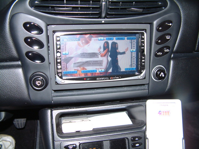
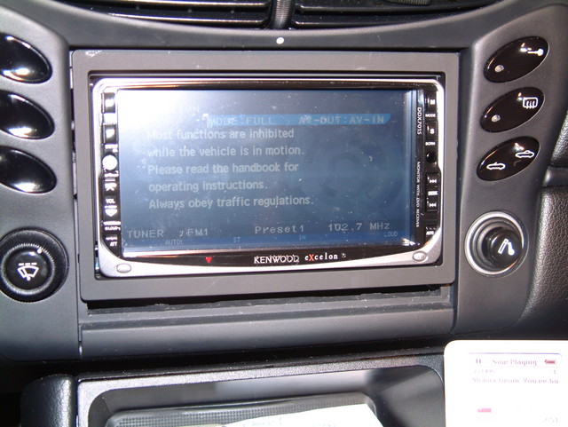
screen looks fine in full sunlight with the top down. You can adjust the screen tilt 6 postions, contrast and brightness also... all adjustments are very quick and easy to do. the picture above has 2 500 watt halogens shining on it to give me more light while i was doing the work at night. The halogen lamp was sitting on the convertible top shining light between the two rollbar hoops (remove the plastic windscreen or it will get melted). that also kept me warm in the chilly garage. -
DIY Kenwood PNAV7015 combo into Boxster
hayaku replied to hayaku's topic in 986 Series (Boxster, Boxster S)
yes they should be. The GAL will be part of your harness behind the radio. Its the pink/gray wire. The reverse wire is under the driver's seat. Good luck with the install -
DIY Kenwood PNAV7015 combo into Boxster
hayaku replied to hayaku's topic in 986 Series (Boxster, Boxster S)
Oh I understand what you are asking now... the BOSE system uses a MOST fiber optic cable. So the answer is no.... you can't splice in rca plugs into a fiber optic cable. The kenwood headunit does have a fiber optic output, but I don't know if its able to talk to the alarm unit on the MOST bus. -
DIY Kenwood PNAV7015 combo into Boxster
hayaku replied to hayaku's topic in 986 Series (Boxster, Boxster S)
why not? all i did was tapped the line-in wires to the amp with rca plugs. i have the HAES 4x40 amp. the C1 yellow plug is where the stock headunit has its pre-out line level outputs to the amplifier. not much to an amplifier is there? power, remote power on/off, ground, line inputs, speaker outputs... -
DIY Kenwood PNAV7015 combo into Boxster
hayaku replied to hayaku's topic in 986 Series (Boxster, Boxster S)
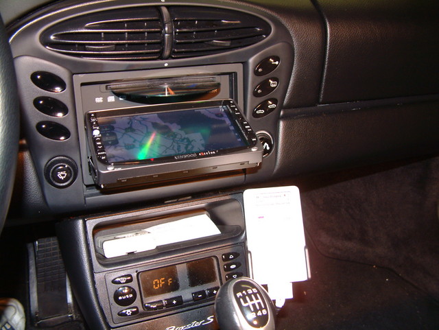
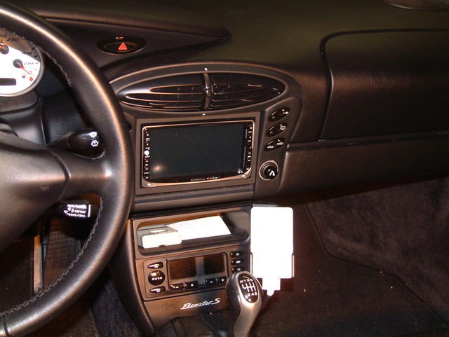
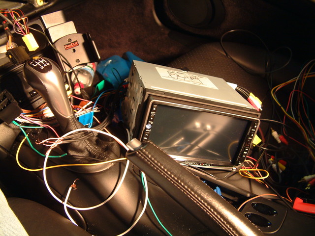
more pics
-
DIY Kenwood PNAV7015 combo into Boxster
hayaku replied to hayaku's topic in 986 Series (Boxster, Boxster S)
more pics
-
DIY Kenwood PNAV7015 combo into Boxster
hayaku replied to hayaku's topic in 986 Series (Boxster, Boxster S)
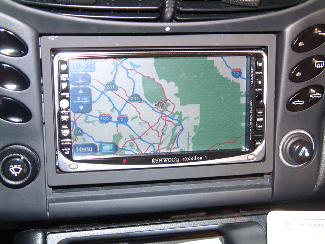
Step 13. Finish connections turn the key off remove the battery again drill the final mounting holes for the nav unit in the front turnk and mount it with the supplied hardware. disconnect all headunit cables and remove the headunit Reinstall the main trim piece with the fitted headunit bracket. Screw in the 4 torx screws hand tight. Reinstall the alarm flasher plate on the dash using the torx socket to finger tight. Reinstall the alarm flasher cover plate over the flasher light and gps antenna Reintall the side trim pieces and make the plug connects by color coded plugs. Reinstall the seat bolts and torque to 48 lb-ft Reinstall the rail covers over the front seat bolts On the main trim piece, you will notice there is a metal tab on the side where a single wire was connected to. This is the radio alarm wire and it expects a ground signal to the chassis. You can wire this up to the black ground wires as a quick fix (what i did) or you can run a wire from a ground point to the chassis of the headunit (like the original was) Finish off our wire connections with clean crimps, wire ties, electrical vinyl tape, etc. Reconnect all plugs again. Slide the headunit into the mounting bracket making sure not to pinch/crush any wires behind it. I pull the wires in the back of the unit as I push the head unit in. Put on the headunit trim piece. If you are so inclined, you can fill the small gap at either the top or bottom of the headunit with plastic for the finished look. Step 14. Calibration of GPS Start the car, and reposition the car to your address. Drive for about 6 miles at 25 mph or faster to get the GPS unit to calibrate your speed, heading, tire speed. step 15. All done. See PICs
-
DIY Kenwood PNAV7015 combo into Boxster
hayaku replied to hayaku's topic in 986 Series (Boxster, Boxster S)
Step 9. Connect Headunit harness to factory harness Plug in the Scosche VW10B harness adapter to the factory black connector that went into the original head unit. You are only using the lower set of wires. The upper set of wires are for direct connect speakers. Since we are re-using the the factory amp, we disregard the top plug connect and the top set of speaker wires. *** Constant Battery Power and Switched Power are reversed. Connect all black wires together (2 from the Headunit and 1 from the Nav to the 1 from the scosche adapter) for ground Connect all yellow wires from the kenwood equipment (2 from headunit, 1 from nav) to the Red Scoshe adapter wire for constant power Connect all red wires from the Kenwood nav and headunit to the yellow Scoshe adapter wire for switched power Connect all green wires (2 - 1 from headunit and 1 from nav) to parking switch +++ I connected this to the black set of wires so I have full time nav and video functions instead of it being disabled by speed. Connect Scoshe VWAB antenna adapter to factory antenna plug Connect the plug wire from the headunit harness to the misc wire you connected to C1, Pin 6's wire for remote amp on/off signal. Connect the white wire (speed)from the nav harness to the brown wire on the scoshe adapter (the one that connects to the gray/pink wire - pin 1 of the original black plug) Connect all orange wires (1 from headunit, 1 from nav) to the orange scoshe adapter wire for illumination control Step 10. Connect Nav Unit in front trunk Screw in the mounting brackets on the side of the nav unit using supplied hardware Connect the wire harness plug to the nav unit Connect the brown IFC cable to the nav unit Connect the GPS antenna to the nav unit Step 11. Connect Headunit to harness Connect the small wire harness to the headunit Connect the large wire harness to the headunit Connect the brown IFC cable to the headunit Connect the RCA preout cables you made to the headunit's rca female preouts Connect the antenna to the headunit Step 12. Test unit Make sure all connections are made and nothing is left exposed. Put the driver's seat back in the car and plug in the seat Install the battery and connect ground first then positive terminals Pull down the door on the nav unit and insert the correct dvd disc Insert the key and turn to the on position Turn the head unit on and test functions If all is good, you have sound and can control the nav on the touch screen as expected.
-
DIY Kenwood PNAV7015 combo into Boxster
hayaku replied to hayaku's topic in 986 Series (Boxster, Boxster S)
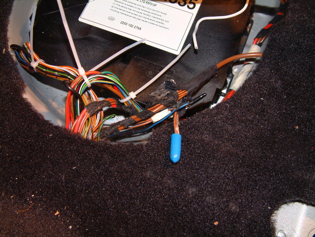
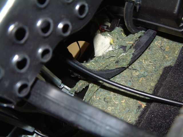
Step 7. Run wires from Nav in front trunk to console Feed the nav wire harness and brown IFC cable through the carpet at the 2nd plug run the wire harness and cable along the strut brace arm, behind the hoses, behind the battery tray and into the 1st plug into the cabin Get inside the car, under the dash and pull the rest of the wires and cable through Feed the rest of the cables through the center console Bundle what excess you have to make it nice and neat and take up less room with zip ties Step 8. Connect Reverse Wire Under driver's seat Fish the pink reverse wire from the nav harness under the center tunnel's carpet Cut the tape on the wire harness for the control unit under the seat Find the Black wire with the blue strip that is not connected to anything. Mine was found bundled in with the brown grounding wires, taped really good. Connect the pink reverse wire to the Reverse wire (black wire with blue strip) See pic
-
DIY Kenwood PNAV7015 combo into Boxster
hayaku replied to hayaku's topic in 986 Series (Boxster, Boxster S)
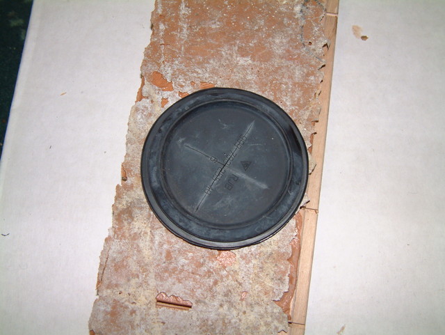
Step 6. Firewall Passthrough plug setup Cut an "X" with a utility knife into the the 2 rubber plugs: 1st plug from behind the battery 2nd plug from behind where the factory cd changer would mount Cut an "X" into the carpet where the 2nd plug is at See Pic
-
DIY Kenwood PNAV7015 combo into Boxster
hayaku replied to hayaku's topic in 986 Series (Boxster, Boxster S)
Step 5. Tap in RCA male plugs to the C1 plugs Find the Yellow C1 plug. Strip back about 3mm of each of those wires Cut your RCA Stereo cable about 6 inches from the both sides. Strip back about 1 inch of wire to expose the grounding strands surrounding a sleeved red and white wire in each. Seperate the grounding strands and twist it into 1 single wire. Strip the inside wire back about 1/2 inch. You now have a positive and negative lead to an RCA male cable Solder the RCA's 4 negative grounding strands all into one wire and into the stripped section of pin 5's wire. Tape that up with the electrical vinyl tape. Solder the positve leads of the RCA cables into the corresponding Pin. Solder the misc wire to the Pin 6's stripped wire part for the amp remote on/off signal. Pin 6 - The Black/Red wire is the ampifiler remote signal to turn on/off the amplifier Pin 5 - The speaker ground wire. This is the one that 4 wires are merged into one. Pin 1 - Rear Left Pin 2 - Front Left Pin 3 - Rear Right Pin 4 - Front Right Now your have RCA connectors spliced into your C1 plug See Pic