Welcome to RennTech.org Community, Guest
There are many great features available to you once you register at RennTech.org
You are free to view posts here, but you must log in to reply to existing posts, or to start your own new topic. Like most online communities, there are costs involved to maintain a site like this - so we encourage our members to subscribe or donate. All subscriptions and donations go to the costs operating and maintaining this site. We prefer that guests take part in our community and we offer a lot in return to those willing to join our corner of the Porsche world. This site is 99 percent member supported (less than 1 percent comes from advertising) - so please consider an annual subscription or donation to keep this site running.
Here are some of the features available - once you subscribe RennTech.org
- View Classified Ads
- DIY Tutorials
- Porsche TSB Listings (limited)
- VIN Decoder
- Special Offers
- Paint Codes
- Registry
- Videos System
- View Reviews
- and get rid of this welcome message
It takes just a few minutes to register, and it's quality Porsche information at a low cost.
Contributing Members also get these additional benefits:
(you become a Contributing Member by subscribing or donating money to the operation of this site)
- No ads - advertisements are removed
- Access the Contributors Only Forum
- Contributing Members Only Downloads
- Send attachments with PMs
- All image/file storage limits are substantially increased for all Contributing Members
- Option Codes Lookup
- VIN Option Lookups (limited)


jpflip
-
Posts
684 -
Joined
-
Last visited
-
Days Won
9
Content Type
Profiles
Events
Forums
External Paint Colors
Downloads
Tutorials
Links Directory
Collections
Classifieds
Store
Everything posted by jpflip
-
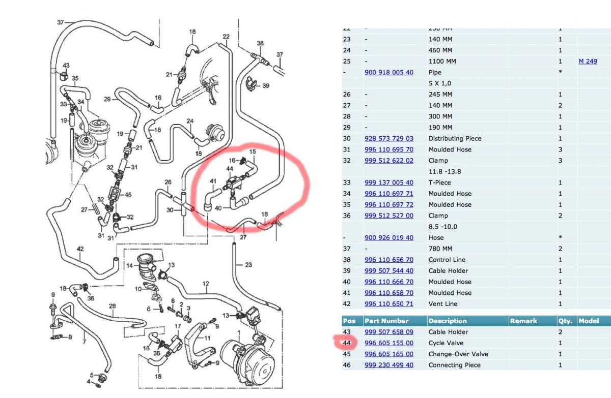
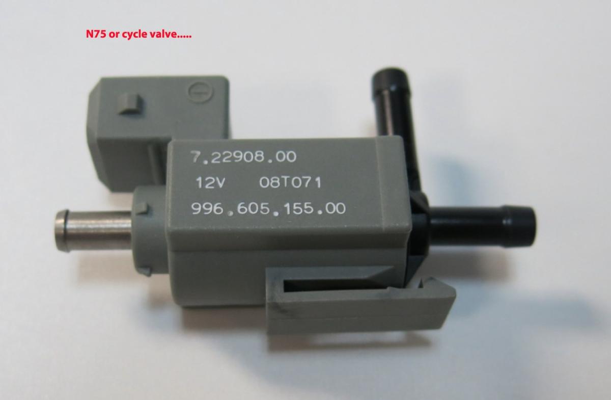
Hey hey Mike!!! Welcome to Renntech. I already mention on Rennlist that I am suspecting one of the sense line coming to or going from the N75 valve also called by Porsche cycle valve or timing valve. After you removed the airbox and also the intake assembly (not a big job) you will found a lot of small black sense lines. Look closely to see if they are attach properly in every position and has far you can see. Going to the right towards the recirculation air pump and also to the N75 valve. This is a grey small plastic rectangular box with sense line going to it and also an electrical plug. It is located just below the fuel cooler. See pictures for help....Remember you can get the repair manual for the TT on 6speed if you need direction for the removal of the airbox or the intake: http://www.6speedonline.com/forums/996-turbo-gt2/228714-ok-guys-here-link-shop-manuals.html

-
P1675 Porsche fault code 658 - Fault - engine purge fan
jpflip replied to Silver_TT's topic in 996 TT, 996 TT S, 996 GT2
Agree with the three gentlemen especially you are talking about 25 minutes sessions and the outside temperature at 80'F!!! I'm sure you will get some more track time since the summer is only starting! -
:welcome:
-
I don't know why Porsche engineer decided to show it blank on the fuse location diagram but in the wiring diagram it is in fact a second power source for the engine compartment fan. The fuse B4 receive his power directly from the battery and the current distributor. Fuse C5 receive his power from the fuel pump relay. Why? Because this fan can run even when you switch the ignition off to keep the engine compartment temperature below 78 F and it does that up to 40 minutes after shut down. When the switch is selected to ignition the fuel pump relay his energized also the power is switch over (in the engine compartment fan relay) to the fuse C5 and ready in case of demand. The switch over is control by the DME or ECU.
-
fuse box copy (fuses location)
jpflip replied to mikop1's topic in 996 Series (Carrera, Carrera 4, Carrera 4S, Targa)
In fact the engine compartment blower got two source of power. I don't know why the fuse diagram did not show C5 but the wiring diagram does. There is a primary source of power directly from the current distributor to the fuse B4. The alternate route is to fuse C5 which is taking power from the fuel pump relay. That is why the fan can run to cool the engine compartment even after ignition switch to off because power is coming from B4 which got power from battery. It will modulate for 40 minutes after shut down to keep engine compartment temperature below 78 F. This function is control by the DME which is controlling the relay switchover between power source..... -
P1675 Porsche fault code 658 - Fault - engine purge fan
jpflip replied to Silver_TT's topic in 996 TT, 996 TT S, 996 GT2
The picture from JFP post #80 shows "The Hook" from Power probe inc (around $400.00) but I think the Power probe III can do the job and it is around $100.00 but I think it is not reading amperage. -
P1675 Porsche fault code 658 - Fault - engine purge fan
jpflip replied to Silver_TT's topic in 996 TT, 996 TT S, 996 GT2
Just checked and the part# is in fact supersede by 99762404601. Too bad we could not check the current draw but we have to admit, after all the test you've done, the fan has to be at fault. Good luck with the installation of a new one and , of course, let us know if it work!!! Welcome it was a pleasure to help you. -
P1675 Porsche fault code 658 - Fault - engine purge fan
jpflip replied to Silver_TT's topic in 996 TT, 996 TT S, 996 GT2
Very good point Ahsai, thanks for sharing your knowledge. -
P1675 Porsche fault code 658 - Fault - engine purge fan
jpflip replied to Silver_TT's topic in 996 TT, 996 TT S, 996 GT2
Yeah, that would be real popular on the home front.....................not! :eek: Of course I was just kidding JFP!!! I think we can consider Silver fan at fault! I was unable to check the current draw of my fan due to a faulty multimeter. Good to know that I need a new one now!!! Fan part# 996 624 036 04 and only $74.80 at Sonnen.... -
P1675 Porsche fault code 658 - Fault - engine purge fan
jpflip replied to Silver_TT's topic in 996 TT, 996 TT S, 996 GT2
JFP leave me your phone number, next time I will wake you up!!!! :D I am going in my garage with my computer and an ammeter. I will give you the exact amp the fan should pull! You are right, it should pull less tan 15 amps!!! -
P1675 Porsche fault code 658 - Fault - engine purge fan
jpflip replied to Silver_TT's topic in 996 TT, 996 TT S, 996 GT2
Obviously the fan seems to be pulling too much load. You are at the fan and nothing blows, my guess the fan is at fault...Strange behavior that can be test using an ammeter in series with the red and black wire but I'm not sure how many amps the fan should pulled....doing some research now.... -
P1675 Porsche fault code 658 - Fault - engine purge fan
jpflip replied to Silver_TT's topic in 996 TT, 996 TT S, 996 GT2
With the fan unplugged select durametric function engine compartment fan "ON" what happen with the fuse? Sorry I've never used those fuse before. I don't think they are resettable and the only feature is once blown a light come "ON" to facilitate the identification in the fuse box.... -
P1675 Porsche fault code 658 - Fault - engine purge fan
jpflip replied to Silver_TT's topic in 996 TT, 996 TT S, 996 GT2
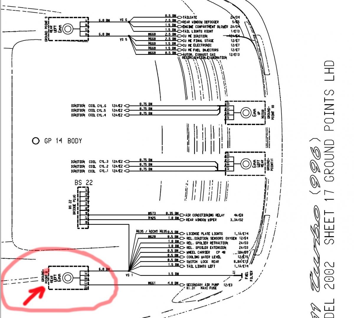
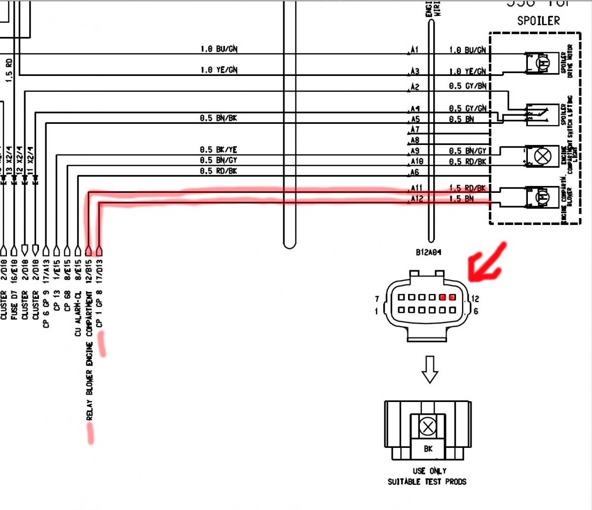
The plug in the engine compartment got 12 wires. 2 of them are for the fan. A12 is going to a common ground called ground #8 on the left side of the car. I think it can be seen from under the car. And E11 is our power coming directly from the relay.... -
P1675 Porsche fault code 658 - Fault - engine purge fan
jpflip replied to Silver_TT's topic in 996 TT, 996 TT S, 996 GT2
Good....The ground for the fan is also a possibility (I can be wrong about my black and red wire...). The contact point for the ground (common ground for many systems) is #8 which is located on the left of the car but the exact location , I'm not sure....This is going to be our continuity check for the brown wire or connection A12....
-
P1675 Porsche fault code 658 - Fault - engine purge fan
jpflip replied to Silver_TT's topic in 996 TT, 996 TT S, 996 GT2
Another good suggestion for you Silver !!! -
P1675 Porsche fault code 658 - Fault - engine purge fan
jpflip replied to Silver_TT's topic in 996 TT, 996 TT S, 996 GT2
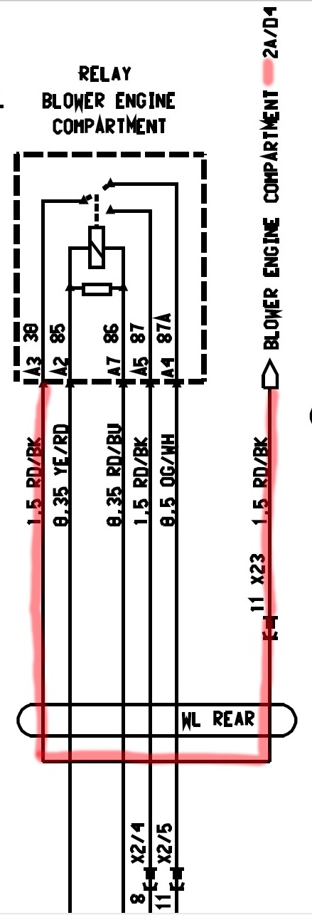
The wire at fault has to be between the relay and the fan. Because before the relay the wire from our power source , fuse B4, is always powered. Here you got the contacting point of the relay. A3 is the black and red wire going to the engine compartment plug and to the fan...This is the wire I suspect.....For your information A2 is the signal from the ECU and A5 is the power from fuse B4....Remember, only when the relay is energized that we got a short.....
- 102 replies
-
- 1
-

-
- p1675
- engine purge fan
- (and 1 more)
-
P1675 Porsche fault code 658 - Fault - engine purge fan
jpflip replied to Silver_TT's topic in 996 TT, 996 TT S, 996 GT2
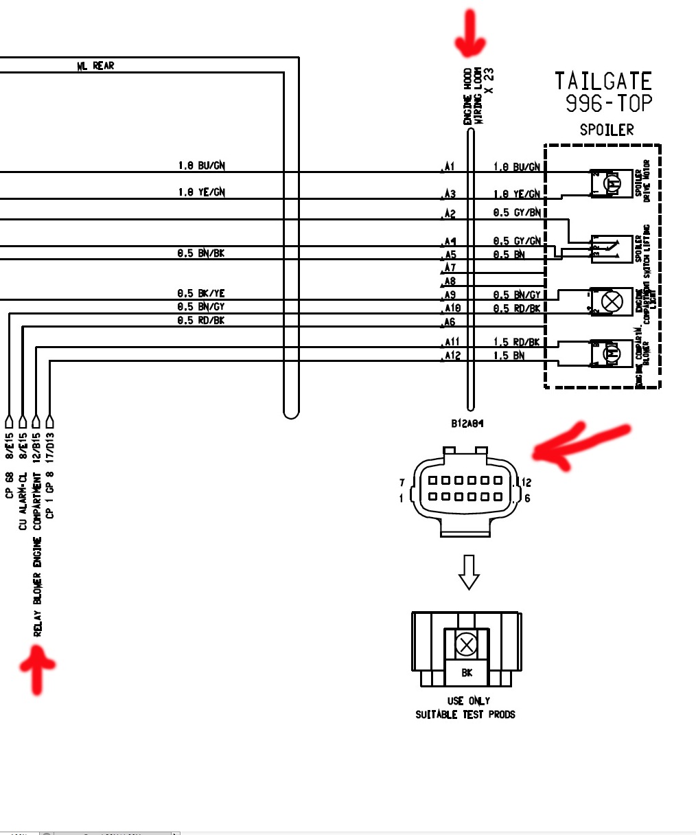
The plug in the back is a good starting point. The wires you have to look at are A11 black and red and A12 brown wire. Use your ohmmeter and check the for a ground for the black and red or A11 (ohmmeter connected between the frame and the wire)....If nil found go to the portion going to the front of the car with the relay removed and see if you got a ground again on A11 because it is the only one going to the relay. If nothing you've eliminated the aft portion of the wiring....
-
P1675 Porsche fault code 658 - Fault - engine purge fan
jpflip replied to Silver_TT's topic in 996 TT, 996 TT S, 996 GT2
On post #5 you mention that you unplug the fan , installed a new fuse at B4 and select ignition but did you select the fan to work with Durametric... The fan circuit was not powered only with the ignition switch selected on, unless the engine compartment temperature was above 172...Hum....You definitively got a short somewhere.... B4 is always blowing so we got a short on the black and red wire.....If the plug in the engine compartment is clean you will have to follow the wire..... Was there anything done to the car before you had the initial fault? -
P1675 Porsche fault code 658 - Fault - engine purge fan
jpflip replied to Silver_TT's topic in 996 TT, 996 TT S, 996 GT2
jpflip, are you talking about the temperature sensor? looks like a long skinny black bottle nipple? i unplugged the connector to it and it looked good on the wire side. I can post a picture if you want to see it, it's easy to pull off. On the right side, if you follow the wires coming down on the right deck hinge you will see a plug with 12 wires.... Also follow the two freon hoses from the air conditioning compressor You will see the plug just above those hoses....
-
P1675 Porsche fault code 658 - Fault - engine purge fan
jpflip replied to Silver_TT's topic in 996 TT, 996 TT S, 996 GT2
:D I'm so slow to type!!!! The power for this fan is really a simple circuit. But there is a plug on the right side of the engine compartment that I would like to look at if it is clean and in proper condition. This plug also include the wires for the spoiler functions. -
P1675 Porsche fault code 658 - Fault - engine purge fan
jpflip replied to Silver_TT's topic in 996 TT, 996 TT S, 996 GT2
If you got a spare 12 Volts battery not far or another car that you can bring close to the TT. With two long enough wires about 12 to 14 gauge just connect the wires directly to the fan and see if the fan start easily. Of course if the fan is at fault your wires will became hot. But we are working with 12 volts here not 220 !!! Also removing the fan from the deck is not a big job if you want to try it on your car battery. -
P1675 Porsche fault code 658 - Fault - engine purge fan
jpflip replied to Silver_TT's topic in 996 TT, 996 TT S, 996 GT2
(sorry if I am repeating a step you already did but...) Very good troubleshooting so far. There is a possibility , your fan is pulling too much load to operate and blow the fuse. First, the blades on the fan, can it be turn easily? Did you tried to connect the fan directly to the battery. No worry about the + or - since the fan will operate in one direction or the other... Red and black wire is the positive. -
With your PST2 you can reprogram the remote functions of your keys and the 24 digits numbers at the bottom of the label is a must! You will found the complete operation of "Re teaching the hand held transmitter" on page 1155 of the repair manual. But it is important to know that you have to follow the "exact" step by step instruction of the repair manual and you will also need the IPASS code from the dealer. IPASS code being a series of code, specific for your car, needed to reprogram different systems.
-
No danger in removing the oil filling tube. The amperage reading should be done with the positive battery cable disconnected and your multimeter (selected to amps) in series between the positive cable and battery positive. Of course you do this with the engine not running.
-
Thanks JFP, I should replace it when I had my engine out...May be next time :thumbup: