Welcome to RennTech.org Community, Guest
There are many great features available to you once you register at RennTech.org
You are free to view posts here, but you must log in to reply to existing posts, or to start your own new topic. Like most online communities, there are costs involved to maintain a site like this - so we encourage our members to subscribe or donate. All subscriptions and donations go to the costs operating and maintaining this site. We prefer that guests take part in our community and we offer a lot in return to those willing to join our corner of the Porsche world. This site is 99 percent member supported (less than 1 percent comes from advertising) - so please consider an annual subscription or donation to keep this site running.
Here are some of the features available - once you subscribe RennTech.org
- View Classified Ads
- DIY Tutorials
- Porsche TSB Listings (limited)
- VIN Decoder
- Special Offers
- Paint Codes
- Registry
- Videos System
- View Reviews
- and get rid of this welcome message
It takes just a few minutes to register, and it's quality Porsche information at a low cost.
Contributing Members also get these additional benefits:
(you become a Contributing Member by subscribing or donating money to the operation of this site)
- No ads - advertisements are removed
- Access the Contributors Only Forum
- Contributing Members Only Downloads
- Send attachments with PMs
- All image/file storage limits are substantially increased for all Contributing Members
- Option Codes Lookup
- VIN Option Lookups (limited)


KentV
-
Posts
19 -
Joined
-
Last visited
Recent Profile Visitors

KentV's Achievements
Member (1/1)
12
Reputation
-
Guys, there's so much about this. But I can't seem to find a detailed pictorial. Here's my question: With the small access panel removed from the center console, I can see that little $6 switch in there. It's right under the hand brake. How do I remove it? It's force fit with a plastic barb. Do I just break it out? Slide an "L" shaped screw driver behind it? Will the barb on the switch break off easily without harming the aluminum bracket? Will the new one be a royal pain to re-insert? Thanks all.
-
Boxster S Instrument Panel Problem--LED Blew Up
KentV replied to KentV's topic in 986 Series (Boxster, Boxster S)
It's a 2000. -
I've never seen anything like this. The orange LED lights for my oil gauge in the instrument cluster are no longer visible and appear to have exploded. What I see is a blotch of orange that I can best describe as a maple leaf design on the lens of instrument cluster. It's as if the lights sprayed out under pressure and have applied themselves to my cover lens for the speedometer, clock, etc. It appears that, maybe, the inside of the lens has diode substance all over it. Has anyone heard of this occurrence? Tell me it's common? I have 87,000 miles on my Boxster and it's been an amazing, incredible vehicle. Thanks for any help.
-
Boxster '00 S. I pulled into my garage this evening after driving 10 miles and had a puddle of water directly below my coolant reservoir. It was dripping while I watched (as best I could). I filled it to below the max line just this morning. I did so because the coolant showed 1/4 inch below the minimum line. Is there an overflow tube there? Sound like a leak. I replaced that tank 4 years ago. Sheesh
-
My '00 Boxster S has been great. But now my removable radio face plate lights are acting up. Sometimes they're on and very bright. Then, suddenly they either go dim or just shut down altogether. This is the drop down, pull-off face plate that comes with the standard Boxster/Porsche radio. Any ideas here? It really seems that it must be a connection problem unless there is some sort of relay or switch. Maybe it's defective but my dealer says no one has ever needed just a new face plate. Obviously, when they shut down I can't see the channel, the band, the selector options, or anything. Thanks for the help.
-
Are you saying they broken flush with the engine? Are they still protruding? Also, what kind of room do you have to work in? Is this an engine removal coming up? I removed a sheered head bolt on my other fun car last month, but I had plenty of room to work with. Let me know. thx
-
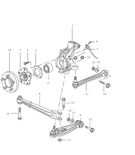
I am posting some notes as to my process in removing the rear half axles from my 2000 Boxster S, and replacing the CV Joint “Boots”, both inner and outer. I hope this will be of use to folks, and I want to acknowledge the good assistance from those on this Board who helped along the way: Note: For tools, you will need a large torque wrench. I bought mine from Harbor Freight for $79.00. I’d highly recommend not only that wrench, but a good set of metric wrenches and sockets, a NAPA CV Boot clamp tool, and a good set of snap ring or “circlip” pliers. I'd also suggest a ball joint separator tool. I’ll leave it to you, but when you order your new boots and clamps, you might want to order new CV Joint end caps, new snap rings/circlips, new hex head bolts for the CV Joints, and definitely new axle nuts, and perhaps a few extra nyloc nuts for the ball joints discussed below. Here is the process I followed: 1. Remove Porsche emblem hub center pieces using a 90 degree bent awl, or similar tool, and loosen, but don’t remove, the 32mm axle nut on each rear wheel axle. 2. Block the front wheels and raise the rear of the car from the middle rear jacking point approved by PCA and Bentleys, just rear of the engine oil sump, where the two bolt heads fastening the under-pan to the frame support appear. 3. Place a sturdy jack stand under each rear jacking point, using a rubber pad or jack stand pad (from Harbor Freight or elsewhere) to protect the car, leaving room to access the forward bolt from the diagonal cross arms on the underside, and gently lower the car onto the stands. 4. Remove each rear wheel and remove each 32mm axle nut, and slide wheels under each side of car as an added “catastrophic” precaution in case the car should somehow fall from the jack stands or should a jack stand collapse. 5. Remove diagonal underside cross arms and under-pan. 6. Remove bolts from each side of sway bar and swing out of way. 7. Remove six hex-head bolts from each inner CV Joint half-axle, and let each axle rest down on the exhaust pipes. Note: Use a nine inch ratchet extension and a good 8mm hex head socket fitting, loosening one bolt at a time, and using the parking brake for each bolt to keep the wheel hub from rotating. The 9 inch extension will help to achieve access to each bolt with the CV Joint Boot kept out of the way. Release the brake to rotate to the next bolt, then reset the brake. 8. Remove each nut from toe-in/track arm at the side of each wheel carrier, then separate ball joint with a ball joint separator tool (Harbor Freight) and, using hand pressure only on the track arm, push the ball joint pin out of the wheel carrier. 9. Remove nut and bolt from the trailing arm to the middle of the control arm, and slide the forked end up the control arm to allow movement 10. Remove nut from control arm ball joint and separate ball joint from control arm. You may have to hold the ball joint pin firmly in place with a torx/star or similar fitting into the top of the pin. 11. Mark the position of the control arm eccentric bolt on the inner mounting point on suspension frame, then loosen, but do not remove the eccentric bolt or the nut on the opposite side. 12. The control arm should now fall freely out of the wheel carrier 13. Pull each wheel carrier out a few inches and place a brace of wood (I used a 1.5 inch square piece, about 13 to 16 inches long) behind the heavy structure of the wheel carrier, squeezed between that carrier and the frame bracket of the control arm. Do this one wheel at a time, not together. The purpose is to hold the wheel carrier outward and firmly in place while you remove the axle from the wheel carrier hub as explained below. 14. Now that you have enough clearance with the wood braces, pound the axle out of the wheel carrier by using a good heavy hammer, perhaps 5 pound one, and buffering the blow to the axle with a small block of wood, perhaps 1.5 inches square and a few inches long. The axle will pop right out. 15. Now remove the wood brace spacer (the 13 to 16 inch one), but realize you must now grab each wheel carrier, pull the carrier out, even farther than the wood spacer accomplished, and remove the axle from the car. A good firm pull is required, and remain confident that neither the brake lines nor the strut will be harmed by the process. 16. Place each axle being worked on in a good vice or on a bench where it can be confined. Tap off the inner end cap, remove the steel snap ring (actually called a “circlip”) with special needle pliers, tap off the CV Joint, in all cases using a piece of wood as a buffer, and then remove the boot clamps and both the inner and outer boots, and clean out all old grease and ascertain that no contamination exists. Then in proper sequence slide the boot clamps and new boots back onto the axle, and repack with CV Boot grease. Be careful not to force grease into the bolt holes of the six hex-head bolts; otherwise, the grease may contaminate any loctite or similar product used when you “re-torque” the bolts at the transmission flange. Also, if you disassemble the inner CV Joint, remember that the ball hub has a camfered inner end that must face toward the axle after you re-grease it and install it into the ball cage, then into the CV Joint. 17. Reassemble in reverse. Torque all fittings. Use loctite where appropriate. You may need to use a jack under the control arm when re-fastening the control arm ball joint nut. When re-tightening the eccentric bolts at the control arm, be sure the markings remain lined up. 18. Only torque the axle nut to 100 foot pounds while on the jack, and even then only carefully. After replacing the wheels and lowering the car, bring the torque to 340 foot pounds, drive the car a few miles and recheck the torque again. Then replace the emblem caps. I hope this helps someone. I’m posting it only because I had some difficulty in my own process, and felt some of the detail here, though perhaps different than offered in other posts, might be useful. The attached drawing will be of assistance in identifying parts involved. Follow all factory torque specs and other mandatory procedures. You may want to check rear wheel alignment when done as well. Good luck all. And use care to be safe. Marking eccentric bolt before loosening: Drawing of axle and control arm/ball joint components: Wheel carrier with axle pushed out: Greasing the CV Joints--the outer joint does not come apart, only the inner: Transmission flange for six hex-head bolts: Working on the removed axle: Removing circlip: Showing CV Joint End Cap to be removed for grease packing:
-
CV Boot Replacement I am posting some notes as to my process in removing the rear half axles from my 2000 Boxster S, and replacing the CV Joint “Boots”, both inner and outer. I hope this will be of use to folks, and I want to acknowledge the good assistance from those on this Board who helped along the way: Note: For tools, you will need a large torque wrench. I bought mine from Harbor Freight for $79.00. I’d highly recommend not only that wrench, but a good set of metric wrenches and sockets, a NAPA CV Boot clamp Author KentV Category Boxster (986) - Common Fixes and Repairs Submitted 07/25/2009 10:13 PM
-
I am posting some notes as to my process in removing the rear half axles from my 2000 Boxster S, and replacing the CV Joint “Boots”, both inner and outer. I hope this will be of use to folks: Note: For tools, you will need a large torque wrench. I bought mine from Harbor Freight for $79.00. I’d highly recommend not only that wrench, but a good set of metric wrenches and sockets, a NAPA CV Boot clamp tool, and a good set of snap ring or “circlip” pliers. I'd also suggest a ball joint separator tool. I’ll leave it to you, but when you order your new boots and clamps, you might want to order new CV Joint end caps, new snap rings/circlips, new hex head bolts for the CV Joints, and definitely new axle nuts, and perhaps a few extra nyloc nuts for the ball joints discussed below. Here is the process I followed: 1. Remove Porsche emblem hub center pieces using a 90 degree bent awl, or similar tool, and loosen, but don’t remove, the 32mm axle nut on each rear wheel axle. 2. Block the front wheels and raise the rear of the car from the middle rear jacking point approved by PCA and Bentleys, just rear of the engine oil sump, where the two bolt heads fastening the under-pan to the frame support appear. 3. Place a sturdy jack stand under each rear jacking point, using a rubber pad or jack stand pad (from Harbor Freight or elsewhere) to protect the car, leaving room to access the forward bolt from the diagonal cross arms on the underside, and gently lower the car onto the stands. 4. Remove each rear wheel and remove each 32mm axle nut, and slide wheels under each side of car as an added “catastrophic” precaution in case the car should somehow fall from the jack stands or should a jack stand collapse. 5. Remove diagonal underside cross arms and under-pan. 6. Remove bolts from each side of sway bar and swing out of way. 7. Remove six hex-head bolts from each inner CV Joint half-axle, and let each axle rest down on the exhaust pipes. Note: Use a nine inch ratchet extension and a good 8mm hex head socket fitting, loosening one bolt at a time, and using the parking brake for each bolt to keep the wheel hub from rotating. The 9 inch extension will help to achieve access to each bolt with the CV Joint Boot kept out of the way. Release the brake to rotate to the next bolt, then reset the brake. 8. Remove each nut from toe-in/track arm at the side of each wheel carrier, then separate ball joint with a ball joint separator tool (Harbor Freight) and, using hand pressure only on the track arm, push the ball joint pin out of the wheel carrier. 9. Remove nut and bolt from the trailing arm to the middle of the control arm, and slide the forked end up the control arm to allow movement 10. Remove nut from control arm ball joint and separate ball joint from control arm. You may have to hold the ball joint pin firmly in place with a torx/star or similar fitting into the top of the pin. 11. Mark the position of the control arm eccentric bolt on the inner mounting point on suspension frame, then loosen, but do not remove the eccentric bolt or the nut on the opposite side. 12. The control arm should now fall freely out of the wheel carrier 13. Pull each wheel carrier out a few inches and place a brace of wood (I used a 1.5 inch square piece, about 13 to 16 inches long) behind the heavy structure of the wheel carrier, squeezed between that carrier and the frame bracket of the control arm. Do this one wheel at a time, not together. The purpose is to hold the wheel carrier outward and firmly in place while you remove the axle from the wheel carrier hub as explained below. 14. Now that you have enough clearance with the wood braces, pound the axle out of the wheel carrier by using a good heavy hammer, perhaps 5 pound one, and buffering the blow to the axle with a small block of wood, perhaps 1.5 inches square and a few inches long. The axle will pop right out. 15. Now remove the wood brace spacer (the 13 to 16 inch one), but realize you must now grab each wheel carrier, pull the carrier out, even farther than the wood spacer accomplished, and remove the axle from the car. A good firm pull is required, and remain confident that neither the brake lines nor the strut will be harmed by the process. 16. Place each axle being worked on in a good vice or on a bench where it can be confined. Tap off the inner end cap, remove the steel snap ring (actually called a “circlip”) with special needle pliers, tap off the CV Joint, in all cases using a piece of wood as a buffer, and then remove the boot clamps and both the inner and outer boots, and clean out all old grease and ascertain that no contamination exists. Then in proper sequence slide the boot clamps and new boots back onto the axle, and repack with CV Boot grease. Be careful not to force grease into the bolt holes of the six hex-head bolts; otherwise, the grease may contaminate any loctite or similar product used when you “re-torque” the bolts at the transmission flange. Also, if you disassemble the inner CV Joint, remember that the ball hub has a camfered inner end that must face toward the axle after you re-grease it and install it into the ball cage, then into the CV Joint. 17. Reassemble in reverse. Torque all fittings. Use loctite where appropriate. You may need to use a jack under the control arm when re-fastening the control arm ball joint nut. When re-tightening the eccentric bolts at the control arm, be sure the markings remain lined up. 18. Only torque the axle nut to 100 foot pounds while on the jack, and even then only carefully. After replacing the wheels and lowering the car, bring the torque to 340 foot pounds, drive the car a few miles and recheck the torque again. Then replace the emblem caps. I hope this helps someone. I’m posting it only because I had some difficulty in my own process, and felt some of the detail here, though perhaps different than offered in other posts, might be useful. For pictures and drawings, I’d refer to Pedro at: http://www.pedrosgarage.com/Site%203/Repla...lf%20Axles.html. Follow all factory torque specs and other mandatory procedures. You may want to check rear wheel alignment when done as well. Good luck all. And use care to be safe.
-
Bentleys doesn't differentiate based on S or non S, rather on the size - Bentleys says: Inner CV joint to output flange M8 29 ft/lb M10 60 ft/lb I'll never understand the physics of it, but 2 more millimeters translates into 31 more foot/lbs?
-
On a Boxster S, the torque for the hex head bolts at the transmission-driveshaft junction apparently is 60 ft/lbs? Whereas, on the non-S, it's 30 ft/lbs? Any clarification would be appreciated. Also, does anyone know if the "ball cage" that surrounds the ball hub inside the CV joint has a forward and backward face. It appears not to be completely symmetrical. Thanks for all the help.
-
WOW, it's been a long time since I've been this stumped. I've always had a good manual. Here are 4 quick questions. HELP: a) If I snap/release the two ball joints on one side, then remove the forked control arm link (track arm), will the strut and spring come flying out? In other words, am I safe removing the control arm mechanisms, and track arm and ball joints with the assumption being that the upper bolts holding the strut together in the trunk are all that is needed? No other support is required? I can't quite tell what holds it all in place once I remove the control arms. Any advice? B) If I loosen the exhaust manifold from the engine do I need to replace the gaskets? c) I don't understand this prior post relating to Boxster CV Joints and gaining more room to remove the axles. Can someone explain this in more detail, as it appears to bear no reality to my '00 S Boxster. It reads as follows: "Loosen the nuts on the exhaust sleeve just aft of the catalytic converter on the side of the axle to be replaced. Remove the nuts (13mm x 3) on the flange between the exhaust manifold and the catalytic converter. Slide the exhaust sleeve onto the catalytic converter to separate it from the muffler. I don't see anything that once loosened will "slide" over the Catalytic Converter, and I don't understand what additional room is being created (or where) to remove the axle. d. Finally, how is the oxygen sensor removed or unpluged? I can't see where there is a plug. Do I loosen the large nut at the base? I'd really appreciate the help. Thanks
-
Any good web sites or other information on where to find a Boxster Service Manual? Unless the Bentley one is really detailed, I'd lean toward a factory one. Thx
-
You are saying the conical part of the ball joint will not fall out of the wheel carrier or that you cannot swing the control arm down and out of the way? If the latter, be sure the radius arm (number 8 in your picture) is disconnected from the lower control arm. It is just a bolt through the bushing. With the bolt out, it will have some room, not a lot, but some to move to allow the arm to go far enough down to clear the wheel carrier. Also the toe adjust arm in the back. If you resort of a pry bar, be careful - steel is way harder than aluminum alloy. OK, Eric, I'm just little confused. You say in one post, "Then move to the wheel carrier, remove the drop link, and get the carrier off the strut, and finally pull it all clear." Are you saying you actually remove the entire wheel carrier from the vehicle? With the entire upper strut mechanism. That seems like a lot of work. You remove the strut? Are you also saying that you took the wheel carrier and half axle out all as one piece. Sorry, just a little more detail please. If I read your post literally, it appears you took everything off that side of the rear suspension. Nothing left. thx
-
I'm really down to one last problem--I think. I've snapped/loosened the ball joint on the lower control arm. But it's still impossible to get the ball joint bolt out of the carrier. The control arm, especially with the track arm from the body connected, that long forked arm (see attached), is just as rigid as can be. I've seen an article that talks of using a large crow bar, so I guess that's my next thought unless I'm missing something easy.