Welcome to RennTech.org Community, Guest
There are many great features available to you once you register at RennTech.org
You are free to view posts here, but you must log in to reply to existing posts, or to start your own new topic. Like most online communities, there are costs involved to maintain a site like this - so we encourage our members to donate. All donations go to the costs operating and maintaining this site. We prefer that guests take part in our community and we offer a lot in return to those willing to join our corner of the Porsche world. This site is 99 percent member supported (less than 1 percent comes from advertising) - so please consider an annual donation to keep this site running.
Here are some of the features available - once you register at RennTech.org
- View Classified Ads
- DIY Tutorials
- Porsche TSB Listings (limited)
- VIN Decoder
- Special Offers
-
OBD II P-Codes - Paint Codes
- Registry
- Videos System
- View Reviews
- and get rid of this welcome message
It takes just a few minutes to register, and it's FREE
Contributing Members also get these additional benefits:
(you become a Contributing Member by donating money to the operation of this site)
- No ads - advertisements are removed
- Access the Contributors Only Forum
- Contributing Members Only Downloads
- Send attachments with PMs
- All image/file storage limits are substantially increased for all Contributing Members
- Option Codes Lookup
- VIN Option Lookups (limited)

Richard Hamilton
-
Posts
1,830 -
Joined
-
Last visited
-
Days Won
13
Content Type
Profiles
Events
Forums
External Paint Colors
Downloads
Tutorials
Links Directory
Collections
Classifieds
Store
Posts posted by Richard Hamilton
-
-
ECs "old" 996TT is up for sale here: http://www.pistonheads.com/sales/219311.htm
-
J
It's MUCH more likely to be the ballast resistor, as that's what controls the low fan speed. There was a guy on PCGB with exactly the same problem.
-
AFAIK the shape of the outside of the speaker grilles is the same for the dash and side speakers, it's just the rear side of the speaker that is angled differently depending on location. I'm sure it is that way in the coupe, but not sure about the cab. If they are the same, then this might help: http://www.renntech.org/forums/index.php?showtopic=15407
-
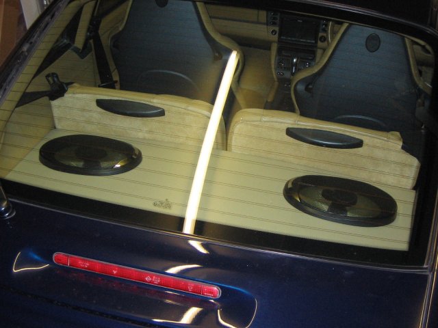
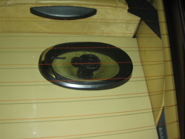
Just a note to add that I spend a couple of hours fitting a nice pair of Pioneer TS-E6996 to the storage box:

At last - some bass!
-
 1
1
-
-
The Valeo looks good. It isn't silicone though - shame.
-
I get mine from Auto Performance Products: http://www.a-pp.com/ - they are about £30+VAT+delivery for the pair.
TBH, I just got two straight blades, which I don't have a problem with, but they do have a curved blade as well.
-
I use the PIAA silicone wiper blades. Not sure if they are available in the US, but they work much better than the standard ones. Much smoother operation, eliminating any judder. After a while they build up a layer on the scren which gives a 'Rain-X' effect. Pricy, but worth it.
-
Loren is correct that the PST2 should show if it is the throttle potentiometer at the pedal end, or the actuator at the throttle body which is the problem. Unfortunately, I'm quite a long way from you otherwise I would have been happy to help. If you need an independent specialist, you could try Parr at Crawley, West Sussex. I've also heard very good things about Addspeed Engineering at Horsham - probably cheaper than Parr too.
Addspeed: 01403 255616
Parr: 01293 537911
-
Also check the anti-roll (sway) bar drop links. Any play in one of the ball joints gets amplified really well.
The rattle in the engine bay might be the airbox - the grommets in the body often come out, and the pin on the bottom of the airbox rattles against the metal.
-
So if I want to fully disable the PCM2 in my Aug 03 Carrera, I will need to remove fuses D8, D9, D10, E6 and E8?
It looks that way to me too. It doesn't look like it will interfere with anything else.
BTW, I think there is a small blade fuse on the back of the main PCM unit too.
-
Check the indicator bulbs. If one of them blows it puts less load on the indicator relay, and they tend to flash faster.
-
Or you can see here: http://www.renntech.org/forums/index.php?s...ost&p=67481 for the fuse layout.
;) ;)
-
Russ
USA and RoW M030 Sports suspension are different. They use different springs, shockers and anti-roll bars. The USA M030 is softer than RoW, and I think that's why the alignment for USA standard (series) and sports suspension are the same. The RoW M030 is 10mm lower than the RoW standard suspension, hence it has different alignment settings.
Sounds like the alignment people have used the wrong settings, confusing the "S" for sport.
-
I'm sure they know, but they have to run the "Sports Car Handover" routine in the Special Functions menu. Good luck.
-
I think Izzy is suggesting that the alarm system, which controls the interior lights, may be in energy-saving "transit" mode. If, as he suggests, the interior lights do not come on when you unlock the car with the remote, then this is likely to be the problem. Unfortunately, you need a PST2 and go through the handover programming routine to set the alarm system to normal mode.
-
996-618-051-02 does not seem to be a valid number. If I were you I wouldn't risk it - try and find one with the matching part number.
Just looked at the Price Search here - That number seems to be for a "Litronic Control Uni", priced at $0.03!!
-
The pre-facelift 996 Carreras use the ZF tiptronic transmission - post-facelifts were MB. 996 Carrera manual transmissions were all made by Getrag.
-
BS11 is Bridge Plug 11, one of the bridge plugs on the relay carrier. There are several bridge plugs there with multi-pin connections for speed signal, brake switch, etc.
17/C8 is the "grid reference" to where the wire goes - in this case Sheet 17, gridref C8.
It would probably help to have the sheets showing the destinations of the wires you are trying to trace. I'll PM you.
-
What Russ didn't tell you was that he is in the UK - hence no air pump was fitted.
-
If it is a cracked or slipped liner, try Hartech (http://www.hartech.org/). Autofarm do the Perfect Bore (http://www.perfectbore.com/) SilSleeve conversion, but I think the Hartech solution is cheaper.
-
GRS
Those outputs were from my first interpretaion of the schematic.
Pin B - maybe I interpreted the schematic wrong - I obviously got D and G right (the other two outputs from the stalk), but it seems that B may be the opposite sense. Looking at it again, I can see that the switch must be normally closed, so you are getting the correct output.
Pin F - I have a Tiptronic, so I can't check the clutch switch. To me, the schematic shows the clutch switch normally open, but I guess it must be normally closed. Therefore I think this must be correct on your car.
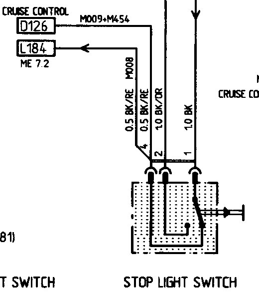
The brake switch only has 3 terminals connected, but they are numbered 1, 2, and 4 - so that's where the confusion probably lies.
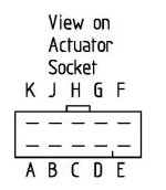
It seems to me that the problem is with your control unit, and the lack of output from pin K might confirm that. It might be worth taking it out, opening it up, and checking for an obvious fault inside. From memory, the circuit board connects to the socket with an edge connector, so it might be worth checking that the pins are clean. Otherwise, maybe you could get a used unit from a dismantler - that's where I got one from for my retrofit.
-
The green cluster light gets its feed from Pin K on the cruise module plug. This wire is also connected to pin 8 of the diagnostic socket, so you should be able to measure 12v+ at that connector with the ignition on, and the cruise switch depressed.
Cruise Module:
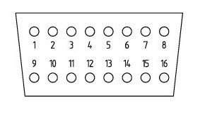
OBD2 Socket:
-
Sorry GRS, the spreadsheet just confused me. Maybe it’s just me that can’t interpret it, but what I think you are better checking is that you are getting voltages at the right places, rather than continuity.
Pin H - Supply - should have 12v+ when the ignition is switched on.
Pin D - Set/Acc - should have 12v+ when the ignition is switched on, the cruise switch is depressed on the end of the stalk, and the lever is pushed to set/acc.
Pin B - Off - should have 12v+ when the ignition is switched on, the cruise switch is depressed on the end of the stalk, and drop to 0v when the lever is pulled to off.
Pin G - should have 12v+ when the ignition is switched on, the cruise switch is depressed on the end of the stalk, and the lever is lowered to resume.
Pin F - Clutch Switch - should have 12v+ when the ignition is switched on and drop to 0v the clutch is depressed.
Pin A - Speed Signal - I think this is a pulse which will vary with speed, and would be difficult to test. If your other speed-related devices (spoiler etc) are working, I would assume this to be OK.
Pin C - Stop Light Switch - should have 12v+ when the brake pedal is pressed.
Pin J - Stop Light Switch - should have 12v+ when the brake pedal is up.
Pin K - Signal out to the Diagnostic Socket & Cluster Light – the control module should give a 12v+ signal out when the ignition is switched on and the cruise switch is depressed on the end of the stalk. It should also have 12v+ for a few seconds when the ignition is switched on with the cruise switch off. The conecctor would have to be plugged in to test this.
Pin E - Ground
HTH.
EDIT: Outputs to pin B and pin F corrected - see later posts - amendments are underlined
-
IMHO it would be really useful if some of you guys could reply with which code Loren suggests actually works. It might help make more accurate predictions. Just my 2 cents worth.
-
 1
1
-
Mass Air Flow Sensor
in 996 Series (Carrera, Carrera 4, Carrera 4S, Targa)
Posted
Joe
The easiest way to do it is to take the MAF off with the connector attached. Once it is out of the air box you can turn it to get at the clip on the back.
HTH
Richard