Welcome to RennTech.org Community, Guest
There are many great features available to you once you register at RennTech.org
You are free to view posts here, but you must log in to reply to existing posts, or to start your own new topic. Like most online communities, there are costs involved to maintain a site like this - so we encourage our members to subscribe or donate. All subscriptions and donations go to the costs operating and maintaining this site. We prefer that guests take part in our community and we offer a lot in return to those willing to join our corner of the Porsche world. This site is 99 percent member supported (less than 1 percent comes from advertising) - so please consider an annual subscription or donation to keep this site running.
Here are some of the features available - once you subscribe RennTech.org
- View Classified Ads
- DIY Tutorials
- Porsche TSB Listings (limited)
- VIN Decoder
- Special Offers
- Paint Codes
- Registry
- Videos System
- View Reviews
- and get rid of this welcome message
It takes just a few minutes to register, and it's quality Porsche information at a low cost.
Contributing Members also get these additional benefits:
(you become a Contributing Member by subscribing or donating money to the operation of this site)
- No ads - advertisements are removed
- Access the Contributors Only Forum
- Contributing Members Only Downloads
- Send attachments with PMs
- All image/file storage limits are substantially increased for all Contributing Members
- Option Codes Lookup
- VIN Option Lookups (limited)


piripiri1
-
Posts
3 -
Joined
-
Last visited
Content Type
Profiles
Events
Forums
Exterior Paint Colors
Downloads
Tutorials
Links Directory
Collections
Classifieds
Store
Everything posted by piripiri1
-
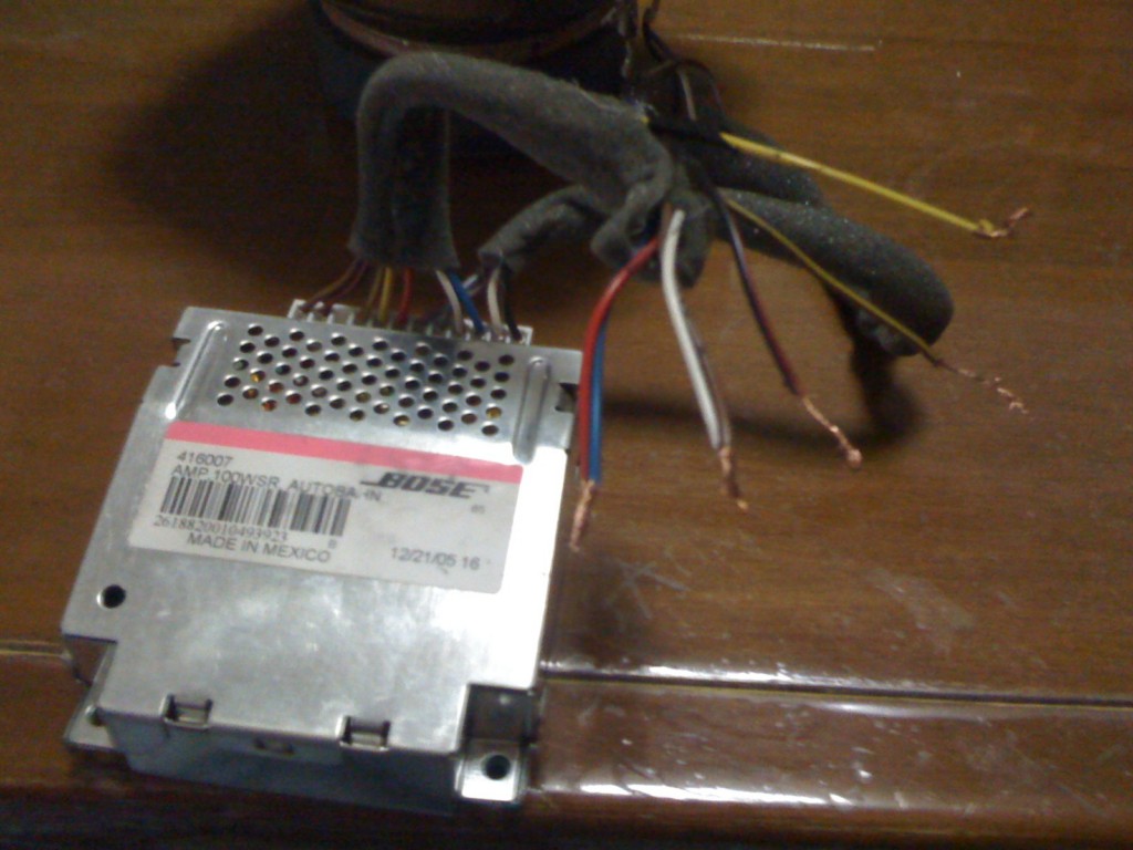
Hello, i'mk convinced that pinout given in the post are the same (form a2 to a6) , problem is remote signal to wake up circuit, i don't know if is a 12V or a 5V signal (not blue wire from the autoradio) , it could be an differential op amp with 5V wake out signal I'll try and i'll make you know, Thanks, :) SOLVED!!!! red+blu=12V, brown+white=ground, red/black=signal+ from amplifier (use signal 5V as remote to turn on) yellow= signal - yellow/brown= signal+ Bye!! :)
-
Hello, i'mk convinced that pinout given in the post are the same (form a2 to a6) , problem is remote signal to wake up circuit, i don't know if is a 12V or a 5V signal (not blue wire from the autoradio) , it could be an differential op amp with 5V wake out signal I'll try and i'll make you know, Thanks, :)
-
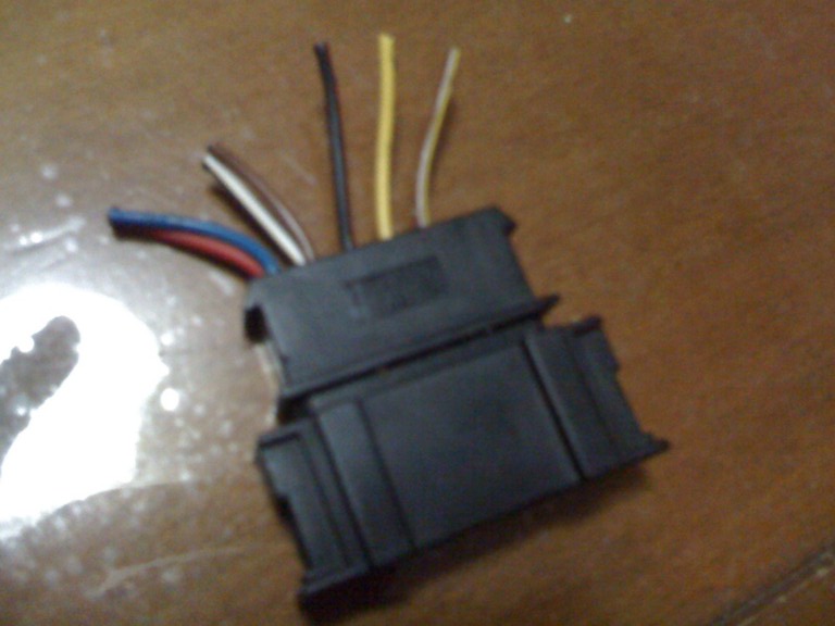
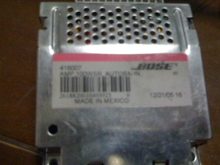
Hello everyone... :D i'm a newbye.... i 've just read this: http://www.renntech.org/forums/index.php?s...amp;mode=linear i've got the same amplifier, but i need pinout!! Colors are different from the post , i'm not able to make it work and there are only 5 pins!! :wacko: HEEEELPPP!! As shown in the picture, there are 5 pins: 1) red and blue joined together (they're also joined on the pcd board) 2) white and brown joined together(together soldered on ground of the pcb board) ( ithink they are + and i input signal from the amp) 3) red/black (i think remote turn on) 4) yellow ??? power feed 5) yellow/gray ???? i can't find the way to know which are power feed and ground , i think that red/blue and white/brown joined together are input signal from amp.... What do you think-....??I'm GOING MAD!!! Thank you..... :) :) :renntech: