Welcome to RennTech.org Community, Guest
There are many great features available to you once you register at RennTech.org
You are free to view posts here, but you must log in to reply to existing posts, or to start your own new topic. Like most online communities, there are costs involved to maintain a site like this - so we encourage our members to subscribe or donate. All subscriptions and donations go to the costs operating and maintaining this site. We prefer that guests take part in our community and we offer a lot in return to those willing to join our corner of the Porsche world. This site is 99 percent member supported (less than 1 percent comes from advertising) - so please consider an annual subscription or donation to keep this site running.
Here are some of the features available - once you subscribe RennTech.org
- View Classified Ads
- DIY Tutorials
- Porsche TSB Listings (limited)
- VIN Decoder
- Special Offers
- Paint Codes
- Registry
- Videos System
- View Reviews
- and get rid of this welcome message
It takes just a few minutes to register, and it's quality Porsche information at a low cost.
Contributing Members also get these additional benefits:
(you become a Contributing Member by subscribing or donating money to the operation of this site)
- No ads - advertisements are removed
- Access the Contributors Only Forum
- Contributing Members Only Downloads
- Send attachments with PMs
- All image/file storage limits are substantially increased for all Contributing Members
- Option Codes Lookup
- VIN Option Lookups (limited)

Porschenstein
-
Posts
36 -
Joined
-
Last visited
Content Type
Profiles
Events
Forums
Exterior Paint Colors
Downloads
Tutorials
Links Directory
Collections
Classifieds
Store
Everything posted by Porschenstein
-
 Hey guys, Does anyone know if you need to inform the DME that the O2 sensors have been replaced? I had a couple of codes about burning lean and aging O2 sensors. Since the car has 80k miles on it, I went ahead and replaced all 4 O2 sensors & cleared the codes. The code for aging sensor on bank one has returned. Any suggestions? Thanks, Ron 2004 996.2 C2
 -
I had a similar issue on my 99. It was the four spoke steering wheel. It is pretty common that the airbag mount gets worn out. I had to replace the mount because mine would either not work or honk the horn when I hit a bump in the road. If you have the four spoke, it might be this same mounting bracket. It was fairly easy to replace.
-
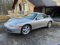
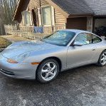
I know it sucks to read through an entire thread and then it ends abruptly with no conclusion. Long story short, after almost 3 years, I gave up. To all those that told me it was a very bad idea to buy a flooded 911, you were correct. I sold it to CogsCogs Porsche graveyard that is close by. Joe is a great guy with a lot of used Porsche parts, and a Porsche transmission expert. He pulled the drivetrain, and the car is currently on eBay. My 2004 C2 arrived this past Wednesday, it’s an awesome car. Really nice condition with 80K miles on it.
-
I purchased a PIWIS 3 from the Autonumen website. I used it on the non-running 99 C2. When I put a thumb drive in it and copied some log files off of it, the thumb drive was littered with multiple viruses. As a test, I formatted the thumb drive, put it back in the PIWIS and copied a single file. Again, when I put it in my PC, it had 5-6 different viruses on it. I have a 04 C2 now, but I’m afraid to even connect the PIWIS to the car.
-
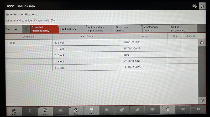
No value for VIN:

-
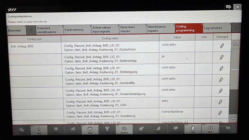
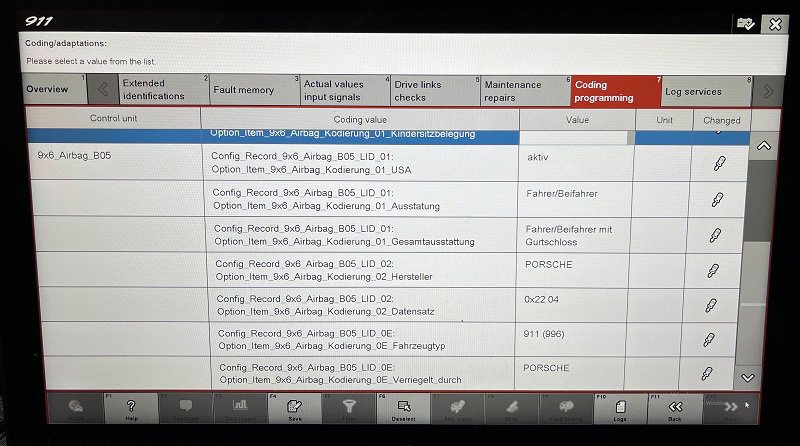
Basic values, ECU Part#, ECU S/N, Unknown Revision maybe, driver side igniter S/N, Pass side igniter S/N. (The igniters are not original either, automatically found)
-
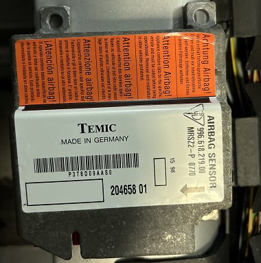
Can anyone say with certainty that the Airbag module can or can't be used in a car other than the one it was locked to? I've seen post saying no it's VIN locked and others saying they used one with no problem. I know this can shut the fuel pump down in a wreck, so I'm wondering if it might have my fuel pump shut down because it is not the original one for my car. I will say from what I've seen, it doesn't appear to be a VIN lock, I think it's locked to the model. I looked at all coded values with the PIWIS in engineering mode and didn't see VIN in there. Just for giggles I told it to lock it and it flashed Model 996 right before it said it was already locked. Those two things lead me to believe the lock is on the model not VIN. Also, it is error free, and it automatically found my two new igniters in the door sills. This guy:
-
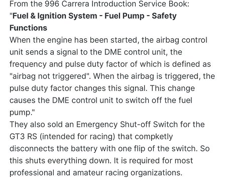
Thanks, same to you. Hopefully now that you have two harnesses you can make one good one. Try to use the minimum amount of solder, I'm told the CAN bus is extremely sensitive to changes in resistance.
-
The X2's were a big ball of green, this is after cleaning up enough to finally get them apart. Before I replace the entire harness I'm going to replace all of the connectors that I had deemed good enough. After discussing how sensitive the CAN bus is with the Indy techs I've decided my good enough was no where near good enough. I repaired broken wires and pins then soaked them in a mild Hydrofluoric acid solution. This did a great job of removing all corrosion but also removed the tin plating. So now the copper is corroding quickly.
-
Okay, I apologize for the snippy comment, as you can imagine I've had tons of "you're wasting your time" comments so I'm a bit hypersensitive but do appreciate a sincere "Good Luck". I also appreciate your time to assist me so far. I'm under no delusions that this should have been an easy project, I knew going in it was a massive and crazy endeavor. At the end of the day it's a machine, determine what all is wrong with it and it will run. This is also a huge crash course on the 996, when I'm done I will be intimately familiar with the car. The main reason I sold my last one was due to how expensive it was to have anything done to the car and I wasn't comfortable working on it myself. Thanks again and sorry for being a smart @ss.
-
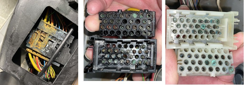
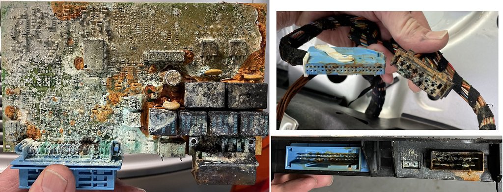
In the first post I included the service values report from the PIWIS and also a link to another thread that covers a lot of what has been done. It's not like I came home with it and said "let's see if it runs". I Immediately gutted it and started looking for and repairing damage. All modules are found by the PIWIS and the report shows what was found. The reason I didn't mention that it was flooded is because responses like "it's a paper weight", and "good luck" aren't helpful and a cop out for people who can't handle a serious challenge. Here's the paper weight BTW, are you sure it was bad?...
-
DME is good, immobilizer replaced & coded. PIWIS can talk to both & test / activate the components that it lets you activate. Same with the cluster. It actually seems very close to being happy, I’ll keep working on the harness and see what happens. Quite the challenge but I have time to play with.
-
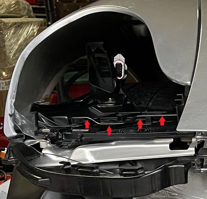
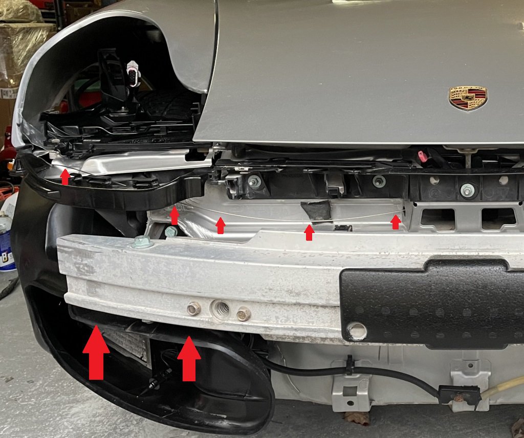
If you can get to this bar from the back you might be able to pop the headlight out by pulling it back to release the headlight, or may have to push it forward, not sure you turn it with the tool, which moves the bar forward or backward depending on which way you turn the tool.
-
You're talking about the front trunk correct? Passenger side should be correct (left hand drive), you might be able to work your way through the rubber that directs air to the radiators. It's really not easy to get to, maybe if you remove the front underbody cover you could find it. You probably could find it with the headlight out but that will be fun since the headlight release is in the trunk, same with the bumper cover, trunk needs to be open to remove it...
-
I took it to a prominent Indy in Atl a few days ago, they couldn’t get it going. Their analysis was the wiring harness is too far gone and must be replaced. The CAN bus is very sensitive to resistance and this harnesses was flooded in saltwater for several days or even weeks possibly. I’m going to try to do a more thorough repair on the harness or replace it.
-
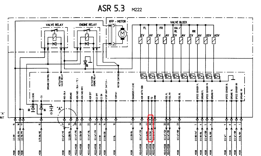
It's on the same page as ABS, I don't see VI/GN going to ABS, maybe ASR in only on C4? Thanks for helping out.
-
I read a Jake Raby post regarding tractor trailer hauling in gear where they have seen issues with the flywheel. I thought maybe it rocked back and forth enough to bend a tooth or something. Thanks for the VI/GN test info, I'm thinking I should check it everywhere. Where is the Anti-Skid Regulator located?
-
On the VI/GN wire, should I only check continuity back to the DME or should it have voltage? Thanks.
-
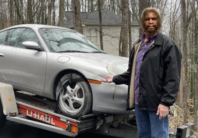
A little harder to admit when you put it like that, but unfortunately the Neanderthal was me. I drove down and picked it up from Copart. I think the tire straps held it tight though.
-
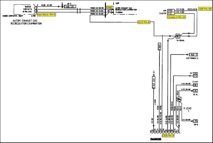
If the CPS signal is not seen but the CPS and wiring test good is it possible the TN-Signal coming back out on pin 80 is not making to the cluster and could cause the Reference Mark to be not seen? I'm assuming this wire feeds the tach. Or maybe the timing ring is damaged? It was towed from Miami to Atlanta in first gear.
-
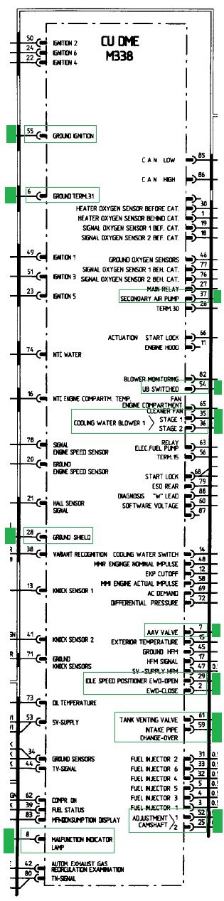
Was that TMI?... In post #1 I attached the Vehicle Analysis Log taken with the PIWIS III. I have only spotted these things as possible no start causes. That's the CrankPS, Airbag Controller and voltage regulator/alternator. DME --- *(Reference mark - signal not present) - wiring and CPS tested good. *(Signal from airbag - not present) - wiring tested good Immobilizer I32 --------------- *(Signal from airbag - not present) - determined this is normal with ignition on not running Cluster ------- *(Signal, terminal 61 - not present) - determined this is normal with ignition on not running Anyone see something else of concern on the Vehicle Analysis Log?
-
I tested the CPS & it's connector back to the DME today. Seems like good news with a lot of possibly bad news and questions. First, all of the CPS & CPS connector results seem fine: Tested CPS pins 1-2 (.886), connected CPS to harness & tested X59/2 pins 9-10 (.886), tested DME pins 78-20 (.886) So CPS and wiring seem good. 0 Ohms on the wires from the DME to the CPS connector with CPS removed. While checking CPS pin 3 I noticed I was getting tones in other places, since it's a ground it makes since that it would tone at other ground connections, but some seem bad. I also checked these results while connected to chassis ground rather than CPS pin 3, almost the same results. While connected to CPS pin 3 testing continuity I received tones in all of these pins, as I said the ground ones make sense. (X59/1 pins 23,24,25) (X59/2 pin 18) (DME pins 2,6,7,8,25,28,29,35,36,37,52,54,55,59,61) --> all toned back to CPS pin 3 Shield Ground. While connected to chassis ground. (X59/1 pins 23,24,25) (X59/2 pin 16,18,23,24,25) (DME pins 2,6,7,8,25,28,29,35,36,37,52,54,55,59,61) --> all toned back to Chassis Ground. I'm thinking this might be normal on a lot of them since I can test / activate most of them via PIWIS or Durametric. X59/1: pin 23 - unknown but grounded pin 24 - Start Lock / Starter pin 25 - Start Lock / Starter X59/2: pin 16 - unknown but grounded pin 18 - CPS pin 3 pin 23 - Throttle Valve Potentiometer pin 24 - Idle Speed Positioner pin 25 - Idle Speed Positioner All of this on the DME connector tones back to chassis ground...
-
✔️ Thanks
-
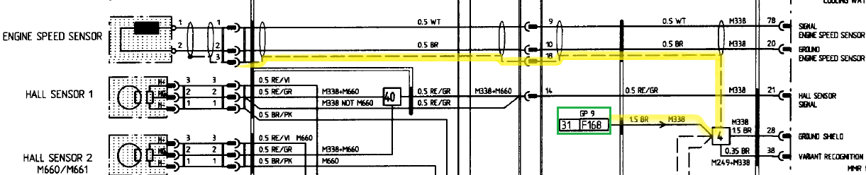
Sorry if it sounded like I'm looking for a short cut, trust me I'm not, I've been trying to sort out what all is wrong with it since December of 2022. The car on the tractor lift is my car... A lot of things were bad, it's been a long journey. I was only trying to clarify that this test (Connect ohmmeter to sensor connector, pins 1 and 3 = 0 ohm) is done with DME unplugged from the harness. --------- And clarify that I'm reading this correct and pin 3 terminates at GP 9. Thanks again
-
So nothing is tested with the DME connected to the harness? Step 1 disconnect battery, wait a bit, disconnect DME? I see now the CPS pin 3 shield I was wondering about should terminate at Ground Point 9, that sound correct? Just working on my game plan before I play with it, I really appreciate you taking time responding.