Welcome to RennTech.org Community, Guest
There are many great features available to you once you register at RennTech.org
You are free to view posts here, but you must log in to reply to existing posts, or to start your own new topic. Like most online communities, there are costs involved to maintain a site like this - so we encourage our members to donate. All donations go to the costs operating and maintaining this site. We prefer that guests take part in our community and we offer a lot in return to those willing to join our corner of the Porsche world. This site is 99 percent member supported (less than 1 percent comes from advertising) - so please consider an annual donation to keep this site running.
Here are some of the features available - once you register at RennTech.org
- View Classified Ads
- DIY Tutorials
- Porsche TSB Listings (limited)
- VIN Decoder
- Special Offers
-
OBD II P-Codes - Paint Codes
- Registry
- Videos System
- View Reviews
- and get rid of this welcome message
It takes just a few minutes to register, and it's FREE
Contributing Members also get these additional benefits:
(you become a Contributing Member by donating money to the operation of this site)
- No ads - advertisements are removed
- Access the Contributors Only Forum
- Contributing Members Only Downloads
- Send attachments with PMs
- All image/file storage limits are substantially increased for all Contributing Members
- Option Codes Lookup
- VIN Option Lookups (limited)


Sandy
-
Posts
28 -
Joined
-
Last visited
Content Type
Profiles
Events
Forums
External Paint Colors
Downloads
Tutorials
Links Directory
Collections
Store
Posts posted by Sandy
-
-
Using OEM Footwell Light switch to install lamps in my 2000 S (utilizing an otherwise blank switch site on the instrument panel). The switch is momentary so I need a relay to operate the lamps - - will one of the OEM relays work, and what are the proper connections to do so? I realize a number of folks have tied FWL into other interior light circuitry, but I like the option of choosing when I want FWL, and I prefer the fully occupied look of the instrument panel as well - - no dummy buttons.
Switch contact #5 is for the Amber LED "Return", according to one schematic I've seen; is this simply a contact for a (typically brown) ground wire?
You might be interested in the info I provided in this thread:
http://www.renntech.org/forums/index.php?s...ic=2245&hl=
I imagine, though, that you would want to connect pin #5 of the FWL switch to pin #5 of the relay to have the amber LED illuminate when your FW Lights are ON, rather than OFF.
-
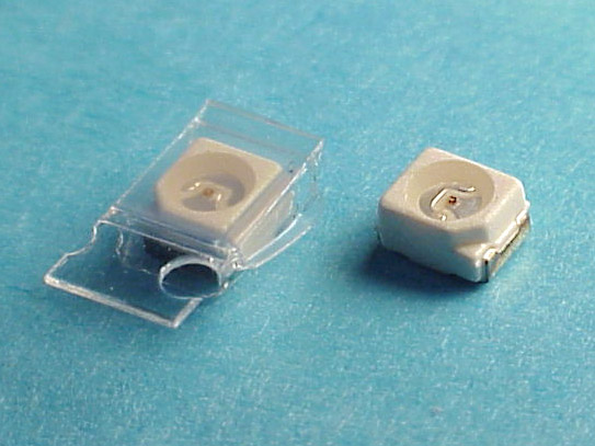
The Digi-Key part no. for the GREEN LED is: 67-1365-1-ND ($0.64 ea.).
The YELLOW LED p/n is: 67-1367-1-ND ($0.64 ea.).
The LEDs are only about 1/8" x 3/32," so the soldering area on each side is miniscule. I would advise ordering more than one LED, in case you accidentally melt the device while soldering it onto the switch's PC board! Take note that the cathode side of the LED is denoted by a diagonal cut at one corner of the LED. You can easily see it on the right-hand LED in the pic. Each LED is sealed in a tiny plastic enclosure to keep humidity out until it's time to solder the LED in place. I used a modeler's knife to cut it away.

-
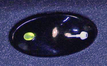
Like you, I found the glare from the red LED to be annoying in my '99 996 coupe. My solution was to replace it with a green LED I purchased from Digikey. It takes some careful soldering with a low wattage iron, but green is a lot easier on the eyes. It also seems more appropriate for indicating the doors are locked. It sometimes is a little hard to see in direct sunlight, so I don't think I'd recommend it for a 996 Cab., or a Boxster. BTW, I also tried an amber LED, but still found it a bit annoying at night.
-
i recently ran the wires for adding switches to run the radiator fans and the engine compartment fans. I was going to use a Footwell Light Switch, but when I tried it the fans only ran when the switch was held down. Apparently it was designed to control a relay and it not a simple on/off switch. Does anyone know of a Porsche tip switch which will accomplish this, i.e. keep the fans on until I switch them off. I would prefer not to mount a non-standard switch.
I don't know of any 986 or 996 toggle switch which mechanically latches, however, a latching relay circuit might be in order. Take a look at the info I posted awhile back:
http://www.renntech.org/forums/index.php?showtopic=2245&hl=
Be careful to observe the current limitation of the contacts on the latching relay as well as the source of +12 volts.
You will probably want the amber LED in the FWL switch to illuminate when the relay is "set," or "on," rather than "reset," or "off. Consequently, you will need to connect the wire coming from pin 5 of the FWL switch to pin 5 of the relay, instead of to pin 1, as I drew it for David T.
-
I take out the key and still get a gong, as if I left the keys in the ignition. Also get the double horn beep when I tried to lock it manually. Appears to be a central locking failure of some sort. Never heard of an ignition switch wearing out at 30K miles. Oh well, one more thing for them to fix at the 30K service:(
Are you sure you're getting a double beep when you lock the door with the key, rather than a single beep?
I once ran a test with my 996 where I intentionally left one of my keys in the ignition switch, forcing the switch contact which senses a key's insertion, closed. After closing the door, I was unable to lock the car using the remote, but was able to do it usng a key in the door lock. The alarm system gave me a single beep when I used the door lock, evidently to remind me that I left a key in the ignition switch!
So, if that one contact of the ignition switch is stuck shut, I guess it would give you a single beep symptom.
One thing you might have to be concerned about if that contact is bad... A couple of systems such as the immobilizer and airbag may be continuously powered, putting a drain on the battery. Have you seen any sign of your battery being a bit weak?
BTW, my ignition switch had to be replaced somewhere around 25,000 miles.
-
I had the infamous airbag lights on. I performed the TSB and took my 99 C4 coupe to the dealer to reset the light. They told me that I need a new sensor (I guess this is the triggering unit 996-618-219-02) I got a new sensor, and want to know what do I need to do after I install it. Do I have to go to the dealer to reset again? The manual talks about “Locking” the unit, what is this? Also, can anyone give me a pointer as to the location of the sensor. I know that is under the dash, but that is the best I can get out of the manual I am using.
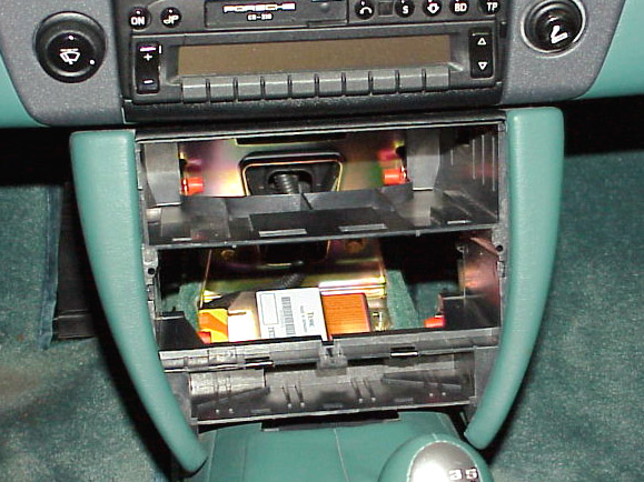
Here's the unit's location on my '99 C2 Coupe.
It's mounted on the floor hump, at the bottom of the forward lower console, underneath the dash. You can just make out the mating yellow electrical connector (orange handle) at its left side. There's a large orange warning label on the top surface of its right side.
You can gain complete access to the unit by removing the carpeted, triangular side-panels at the base of the center console. To remove each panel, unsnap it by pulling gently outward its the forward edge, then slide the panel forward a bit to disengage its aft edge from the base of the console.
-
Hi Sandy,
the relais looks ok on a first glance and like new. The armature moves easily and the contacts aren't pitted. Nothing smoked, blackened, melted....
Do you know whether it can be operated 'manually' ? Could I supply 12V to the pins so that I can check is closing and opening? Should it work with Pin5 (=15) and Pin 7 (=31)?
Well, I'm gonna buy a new one and then we'll see... :o) I must admitt that I am not fully convinced yet that this is the culprit, but I assume I won't find it out otherwise.
Yes, you can bench test the relay, but the hook-up gets a bit difficult because the relay needs to monitor the position of the wiper motor for it to operate normally. The relay normally sees a ground from the motor when the wiper arm is parked and +12v. when the arm is out of the parked position.
I recently bread-boarded the relay on my test bench to run some experiments for determining how to shorten the interval range selected by the rotary control. Consequently, I can give you an idea of what you need to go through to check the relay out.
Pin 1 needs +12v. through a fixed or variable resistor, within the resistance range I previously described. This simulates the potentiometer input from the rotary control.
Pin 2 needs no connection.
Pin 3 is the +12v. output of the relay to the low speed winding of the wiper motor. That winding is used for intermittent and low speed operation. You don't need any connection to this pin to get the relay to operate, just for measurement purposes.
Pin 4 needs a ground to start one intermittent cycle. The ground simulates the wiper parked. If you hold the ground on this pin you will hear one click and release of the relay (the interval being determined by the resistance on pin 1). Removing the ground and reapplying it will give you another single cycle. You need to alternately apply a ground, then +12v., then a ground again, in sync. with the operation of the relay to get a "continuous" sequence of delayed intervals. That is, unless you can actually hook a wiper motor up to the relay, or to a motor with a SPDT switch geared to it, to simulate the limit switch's operation.
Pin 5 needs +12v. (primary power).
Pin 6 needs +12v. to simulate selecting the intermittent mode with the wiper lever arm.
Pin 7 needs a ground.
So, you can see why it would probably be much easier to just try another relay!!!
-
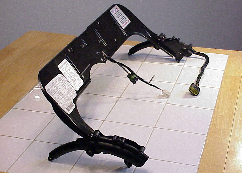
I found this lying there, I'm not sure if it was plugged into something. I can't find anything near it to plug it into. I'm hoping it is supposed to be just lying there.
Thanks for any help.
If the harness has three wires, then it's probably the connector used for making EGR periodic checks. The wires mate with the Motronic. The connector normally doesn't mate with any other connector. However, to keep its contacts clean, it's normally stowed (snap fit) in a black retangular receptacle (box) located at the far right side of the engine compartment just below the spoiler actuator harness' mating connectors.
If you have troble locating the receptacle, I could post a pic. of what it looks like on my '99 996, later this evening.
-
Hi Loren and Sandy,
thanks a lot for the hints!
I checked the potentiometer again and (when using the right pins and the right setup of the multimeter :lightbulb: ) it shows exactly the values Sandy had:
30kOhm full CW
230 kOhm full CCW
So it looks like this part works properly.
Next I followed Lorens tip, looked for the relay (pos16), unplugged it and opened it....
Nothing looks obviously wrong... no black spots, nothing looks 'burned', the soldering looks fine....
Is there a seperate fuse for this relay? Can it be tested?
The relay itself is also rather cheap (20€/25$ refering to my price list), so replacing it seems the easiest way to go.
Greeting from Germany
Wolfgang
There's no separate fuse for the intermittent mode. It uses the same fuse (C6) utilized for the high and low speed modes.
The weakest link in the relay unit is the mechanical relay inside it. You might take a small screwrdriver and see if the relay's armature moves freely and its contacts aren't welded shut. If the contacts look like they're pitted or show signs of arcing excessively, you may be able to dress them with a tool designed for that job, or a narrow strip of very fine sandpaper. It might restore operation temporarily.
-
I would like to thank all the folks that provide the information on this site. I would be in the dark without you.
After review of the wiring digram (provided by this site!) of the power window switch I conclude that it can't be used to control two garage door openers and have the illumination lights hooked up too. Can be forced to work if you want to power your garage remote with a battery (not connected to your car in anyway). Can not share the ground of the car or it will short out. I would not recommend trying it.
Reviewing the other posts it is concluded that the Targa Switch is the best looking candidate anyway for a garage door hack. Part #:996.613.211.910.A05 Before I order one I was hoping to see a wiring diagram. Any one have one.
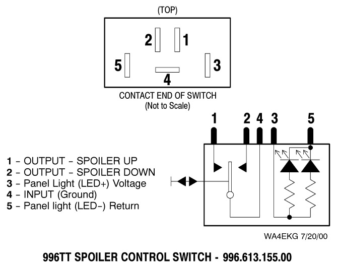
Another choice I have seen is the spoiler control switch. This one will work very well to control two garage door openers and dash-illumination, but doesn't look as good for a garage door.
Thanks
After looking over the wiring diagram for a Targa shade (blinds) switch, its internals appear to be identical to the diagram for a 996TT spoiler control switch which I've attached.
BTW, if you find some other switch which has more desirable graphics on it, you should be able to transfer its toggle (cap) over to the body of a Targa shade switch, or 996TT spoiler switch, and use that combination.
-
In my 996 MJ02 the intermittent wiper does not work properly. If I push the indicator stalk down, the wipers move one single 'round'.
In this position the wipers should now be activated every few seconds, depending on the position of the intermittent wiper dial (a potentiometer).
But nothing happens..... the wipers don't move again.
I removed the potentiometer from the dash, unplugged the cable and checked the power supply. It seems that it's properly powered: When I push the indicator stalk down I get 12V between yellow and black. If I turn the lights on I have 12V between yellow and blue. So I think it cannot be the fuse or power supply to this potentiometer.
Now I checked the potentiometer itself with an Ohmmeter. I can connect any combination of the 4 pins but it shows no resistance. But in a poti at least 2 pins should be conncted with a variable resistance....
- Did anybody experience a similar problem?
- I assume the poti is faulty. Is this a common problem?
The poti itself is rather cheap (~20 Euros/25$), but before I buy I new one I'd like to hear for other experiences.
Wolfgang
Here's some info which may help:
If the potentiometer is open between pins 1 & 2 you would get the exact symptoms you describe. Pin 1 is next to the "little staircase" key/tab side of the connector and mates with YELLOW/RED. Pin 2 mates with BLACK/GREEN. On my'99 996, the pot. measures between pins 1 & 2, approx. 230k ohms when rotated fully C.C.W. and approx. 30k ohms when fully C.W.
I have completely disassembled the rotary control and found it to be quite sturdily built, but I imagine it could go bad, particularly the wiper contact. The laws of probability would seem to suggest that the wiper relay is most likely the culprit, however, if you have carefully measured the pot's. resistance between pins 1 & 2 and it shows open in all positions of the control, that would have to be the problem.
If you have access to some fixed resistors, you could pick a value somewhere within the range I specified above and insert the resistor's leads into pins 1 & 2 of the control's mating female connector. This would allow to verify the relay's operation. Pins 3 & 4 are used only for night illumination. Do you have a fellow 996 owner who would allow you to use his relay for quick troubleshooting?
-
I figured out the switch except for what two spades would be used for the light (internal to the switch, lights when you turn on your dash lights). If I use an adjacent switch for the "light" power what are the wire colors. (2004 Boxster S)
Also what color is/are the wires to the powered cell phone connector. Is this wire always hot?
Looking at the back of the switch, each terminal is labeled with a very, very, small number. The nite illumination terminals are the most outboard terminals (#5 on the left, and #3 on the right). This is, assuming you're looking at the switch, upright, with the two terminals that are very close together (#2 & #1) at the top.
Terminal #3 would normally be connected to a ground (BROWN) and terminal #5 connected to the positive LED dimming bus source (GREY/BLUE/RED) to get the nite illumination functioning on that switch.
You mentioned that you've figured out the switch's internal connections. If you have any doubts about the idiosyncrasies of the power window switch and how it differs from other switches, you might want to check out this link below, to a RennTech thread. The thread has a wiring diagram for the switch and I made a few comments there about the switch's operation.
http://www.renntech.org/forums/index.php?s...557entry29557
Keep in mind, that the ground you connect to terminal #3 on the switch will be felt at the output of terminals #1 & #2 whenever the switch toggle is NOT being pressed.
Here's the female telephone prep. connector connections on my '99 996 Coupe:
#1. RED/GREEN - +12V (fuse E6), from the batt. However, it needs a 7.5a fuse & a second fuse contact installed on the fuse panel to be active.
#2. GREEN/BLACK - +12V (fuse E8), ign. switch position II & III
#3. YELLOW/BLACK - tel. mute
#4. BROWN - ground
-
Valcax,
Would you describe exactly what you are expecting to see? The entire panel illuminates when you switch the exterior lights on, is adjustable for intensity with the control above the clocks. During daylight, the sensor within the rev counter will automatically adjust the intensity of the digital displays *only*. It will not switch the dial illumination on or control its intensity.
If you can see the digits comfortably in all day and night conditions, everything is working OK.
After reading your post I suppose 0586lb is in the right way
Let´s see....
..... there are two kinds of illumination in cluster:
1) Entire panel: Only lights when switch exterior lights. Can be adjusted by switch on cluster.
2) Digital displays: can not be adjusted by switch on cluster. Here is where sensor illumination works. When environment light is dark, digital display is darker. When environment light is clear, digital display is clearer. Always to keep optimal vision of digital displays.
Am I right? :) :) :)
Please confirm my reply.....
Sorry, but you still don't have it exactly right. Let me try this:
First; there is separate INSTRUMENT FACE lighting and DIGITAL DISPLAY lighting on the cluster.
1. The INSTRUMENT FACE lighting illuminates ONLY when you have your exterior lights on. They have ONLY manual intensity control using the left-hand knob, which has a bulb symbol on it.
2. The DIGITAL DISPLAYS are illuminated when you have the ignition on, OR, you have your exterior lights on, OR, when you momentarily press down on either knob on the instrument cluster with the ign. off.
Their intensity is controlled ONLY by the light sensor (high end of the tach.) when ONLY the ignition is on, OR, when you momentarily press down either knob on the instrument cluster with the ign. off.
Their intensity is controlled by BOTH the light sensor AND the left-hand knob whenever your EXTERIOR LIGHTS ARE ON.
So, basically, if your words "ENTIRE PANEL" are referring to the INSTRUMENT FACE lighting, your statement 1) is correct.
Your statement 2) is incorrect, because when your exterior lights are on, the DIGITAL DISPLAY lighting can be controlled by the light sensor AND the left-hand knob.
I have verified the above functions on my '99 996 Coupe. I guess the cluster illumination operation could possibly be different for a 986, but it would really surprise me.
-
Is it possible to change the express windows to normal finger on switch movement? They drive me nuts. I noticed that after you turn off the car, the windows are in the manual mode.
I have a 04 C2.
Thanks,
There is one way to get "half" of what you want.
There is a 12v. input to the front window motors on 996s which PAG calls "RELEASE TAP UP" (BLACK wire). It's supplied from fuse B6. You can see how it works by pulling that fuse. The "auto-up" feature will be disabled. The "auto-down" feature is retained. I tried it on my '99 996 Coupe and every other function affecting window operation that I could think of, seemed undisturbed. Don't know about a Cab. However, the problem is... Fuse B6 also supplies voltage for the 996 TURN SIGNALS. So, leaving the B6 fuse out, renders the signals inoperative!
To perform a mod. on the black wires to get around the problem, would involve getting into your wiring somewhat, probably done easiest at the door hinge electrical connectors.
One thing I didn't have time to experiment with, is the amount of force provided when you "manual-up" the window. I assume it will be maximum force and may not reverse when it encounters an obstruction, as it does when the "auto-up" feature is functioning.
-
Sorry, I couldn't get this reply out to you earlier, but there is a quicker solution for what you needed. Since your low beams are illuminated when your high beams are illuminated (ignition switch on), you just need to monitor the low beams with your relay. That can be done by installing a fuse tap into the output side (upper contact) of either fuse A9 or A10 on your forward fuse panel, underneath the cover. The WT/BK wire feeds both those fuses. Glad to see you found access to the wire by other means, though!
-
Hi guys
My 00 986 seems to have had a headlight failure of some description. When the switch is turned to "on" the lights are on but they are in parker mode, on but dull. High beam and driving lights still work, but not low beam.
Can anyone suggest where to start looking?
The switch seems to work fine, as it dims the interior, activates the driving lights etc, its just that low beam is very very dull
Cheers
Assuming you don't have two burned-out low beam bulbs, here's a couple of other things you could try:
If you have manual height control for your headlights, can you tell if the control is functioning when the lights are on and the ignition switch is on?
Have you checked fuses A9 & A10?
Try wiggling the headlight switch back and forth slightly in the full "ON" position to see if the low beams illuminate intermittently.
-
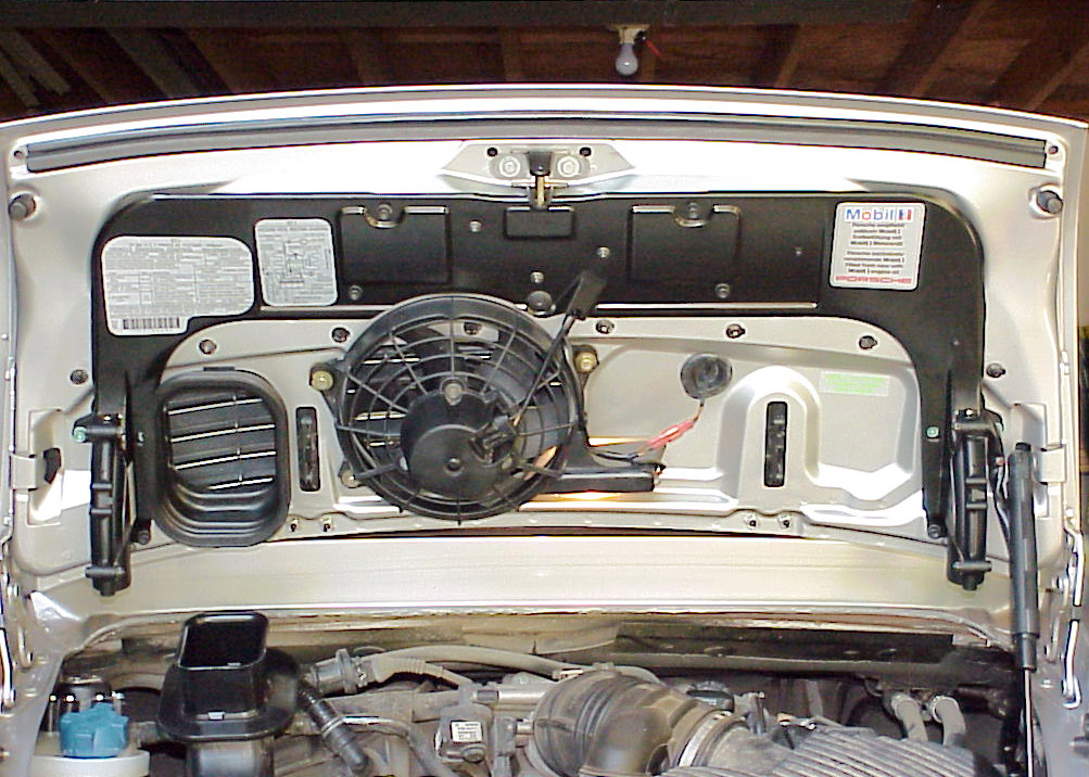
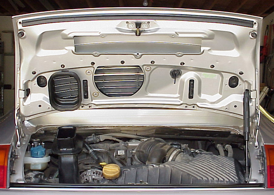
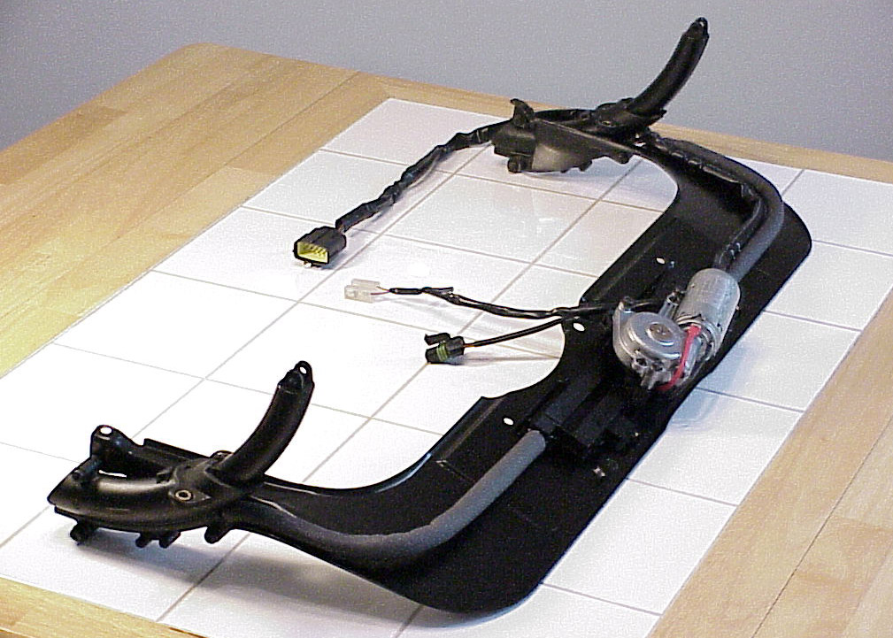
I haven't installed the PAG Carrera fixed spoiler, or an aftermarket spoiler on my '99 996 C2 Coupe, but I have removed and replaced the spoiler actuator assembly from my rear deck lid a couple of times since '98. Perhaps the pics I've attached may help you get oriented.
The spoiler actuator assy. in my pics was removed with the hinged spoiler temporarily left in the extended position, as you can see by the extended arms at each end of the removed actuator assy.
I removed the electric fan assy. only to allow better access to the area beneath the hinged spoiler, which I did not remove. I also didn't remove the "accordian" rubber trim piece at the trailing edge of the spoiler which you may have to remove.
If you have more specific questions, e-mail me. I have several other pics of the spoiler actuator assy., both assembled and disasembled.
-
It doesn't surprise me to see at least one YELLOW/BLACK wire already installed in the pin 3 slot of the black connector (A) for your CDR-23. If your '04 C4S follows the standard used in previous year 996s, that wire goes to the female telephone prep. connector under the center dash area. The wire is the telephone mute input to the head unit. If you don't want to cut and splice into it at the CDR-23, you could do it at the prep. connector, or buy an interfacing male connector such as the 5001.524-276 power/phone mute cable & connector which Becker sells.
One thing you might want to verify though, is that the GREY/RED wire which Becker uses for their harness/adapter/connector packages is actually the mute wire. The only reason I say this is based upon Orient Express' experience with hooking up his iPod.
http://www.renntech.org/forums/index.php?showtopic=5190
He mentions he had to switch the GREY/RED wire with the BROWN wire on the Becker harness when he connected with the prep connector. You might want to e-mail him to be sure exactly what problem he encountered with his installation. It may have been unique to only the part no. harness/connector he used, or perhaps due to the method he chose to wire up his interface.
-
I saw this on Porsche Pete's Boxster board:
http://wa4ekg.home.att.net/996images5/FWLswmod2.html
I thought I was good with electrical stuff, but I get lost at the end of the instructions:
"...will be routed to the instrument cluster where it will be spliced with the piece of cut GREY/BROWN wire of one of the cluster's electrical connectors..."
jeez, does this mean I have to remove the instrument cluster?
At this point, I am asking myself again, do I really want to know if/when the spoiler is up?
Anybody gone through this?
thanks,
navin
Sorry for the confusion Navin. I came up with that mod. back in '01 because some 986 owners were interested in knowing at all times when their spoiler was extended, rather than just relying on the red spoiler warning (disagreement) light to tell them it wasn't up above 70 m.p.h. There's really no need for it in a 996 coupe because you can see the spoiler through the rear window. I'm not sure if that's true with a 996 cab.
I activated the amber LED in the FWL switch on my 996 coupe to monitor my spoiler, only because I had designed my own type of FWL circuit, which didn't require the LED.
The step you were questioning referenced the wiring diagram I included on my site. It shows that if you want to monitor the spoiler, you need to cut the GREY/BROWN wire (spoiler extended) and tap into it through the isolation diode for the amber LED's operation. The FWL switch's contacts can be used for toggling the OBC, or manually operating the spoiler, depending upon what your needs are and how you wire it up. As you can see in my photo, I already had a separate 996TT spoiler switch on my panel for manually operating my spoiler. I also didn't need the FWL switch for my OBC, because I took delivery of my 996 with the OBC stalk installed.
I will probably tear my site down, because there really is no need to modify a FWL switch to get a switch with "non-descript" graphics that has its switch contacts isolated from its nite-lighting LEDs. I figured out soon after I came up with my mod that you can put a FWL switch toggle (cap) onto a 996TT spoiler switch body and get the same arrangement. You just have to paint over the clear lens on the FWL switch toggle, or deactivate the LED beneath it (on its PC board)
Hope this helps, but if you have additional questions, ship me an e-mail.
-
I have not been able to get the memory to work on my seats. (99 996) The power seats work fine, but I can not get the memory to hold. The fuse is good. Any ideas?
Was the fuse you checked, the 7.5 amp. E2 fuse?
-
I'm experimenting with some spare switched, can anyone tell me what voltage I need to apply where to get the dash lighs to light up on a power window switch out of a 99 Boxster? The back looks like this http://www.whiteson.org/boxster/mods/obc/spoilerswitch2.pdf if it is wired the same what would I apply where (out of the car) to get it to light up?
Thanks, Chris.
The power window switch contact connections are configured quite differently compared to the contacts on a 996TT spoiler switch. In addition, the dash lighting (LED) polarity requirements between pins 3 & 5 are reversed because the LEDs' anodes are connected to pin 5 and the cathodes to pin 3. To further complicate things, whatever polarity voltage you connect to pin 3 for the LED illumination (normally ground), will also appear as an output on pins 1 & 2 when the switch toggle is not depressed. I don't have a power window switch diagram made up similar to the one for the spoiler switch, but if I do create one, I'll post it, or e-mail it to you. In the meantime, perhaps Jeff or Loren can post a switch diagram from the circuit diagrams manual.
-
FWIW, when I purchased my 1999 996, I ordered leather sun visors because I had also ordered several other interior items wrapped with Nephrite Green special leather. Each visor had a small, approx. 1" by 3/4" brass-colored, plastic airbag warning "sticker" located on the leather surface, which peeled off easily. I applied some low heat with a hair dryer to the stickers before carefully removing them. The leather on the visors is a bit thin and it looks like I could have torn it if I hadn't softened the adhesive a little.
Unfortunately, however, the hinged, plastic mirror covers on the opposite side of the visors still had the "standard" labels adhered to them! So, I was required to go through the "classic" denatured alcohol sticker removal routine to get those off. Luckily, I was able to get the job done without damaging the surrounding leather.
Of course, things could have changed over the years and PAG may now have a different arrangement on non-ROW leather visors.
-
Can anybody tell me what bulbs the 996 uses for it's rear and front turn signal light bulb, parking light front, license plate light. i found them in the manual but i can't seem to figure out what they are. thanks
Check out this link below:
http://www.sylvania.com/ConsumerProducts/A...placementGuide/
-
You not only need to be concerned whether the "loop" is OPEN at any point, but also whether it is GROUNDED at any point. The loop starts out from the instrument cluster where approx. +11 volts (measured to ground) is passed around the loop and then back into the cluster. If the voltage doesn't make it back because of an open circuit, OR the voltage is dropped due to a short to ground, the BRAKE WEAR caution light illuminates. The loop's sequence, starting out from the source of voltage in the cluster is: RIGHT-FRONT, RIGHT-REAR, LEFT-REAR, LEFT-FRONT, and then back into the cluster.Ok, I measured each new sensor and got a 0.1 ohm reading. So i guess the new cables are ok. Now for the weird part I measured ohms inside the receptacle where the cable plugs in and got 0.3 ohms on the back wheels and 348.0 on both the front wheel sensor plugs. I traced the cables on the front and they go in a bundle with other wires inside the cabin under the dashboard. We move the cables around to identify them but they are together with many more. Is there a relay or module that can be damage, where do I go from here?Keep these things in mind when troubleshooting: First, make sure there's NO voltage present in the circuit when you make resistance measurements, or you will get erroneous resistance readings, second, be sure you aren't measuring resistance back through the cluster.
I suggest you start troubleshooting by disconnecting the RIGHT-FRONT sensor. That way, you can verify you're getting the +11 volts from the instrument cluster and you'll also partially isolate the rest of the loop for additional troubleshooting. With the ignition switch in position 2, +11 volts should be present on the forward male contact in the RIGHT-FRONT connector. If you aren't getting the voltage, that would indicate your problem isn't in the sensor loop. If the voltage is there, turn off the ignition and continue troubleshooting the rest of the loop.
Measure the resistance between the RIGHT-FRONT sensor's leads (female contacts in the connector) to verify it's less than an ohm. Also, check that neither lead shows resistance TO GROUND. Leave the sensor disconnected.
I would then disconnect the LEFT-FRONT sensor and check its resistances. The remaining portion of the loop is now completely isolated from the cluster. You can make a quick check of the other two sensors without having to disconnect them. At the aft male contact on the RIGHT-FRONT connector, check to see there's no resistance to ground. In addition, the resistance from there to the forward male contact in the LEFT-FRONT connector should be an ohm or two, at the most. If BOTH these checks are good, the other two sensors and their wire harnesses should be OK. If the resistance on either check is not correct, you'll have to disconnect at least one other sensor to localize the problem.
It's most likely you'll find one sensor shows continuity though itself, but also happens to measure low resistance to ground.
NOTE: The male pin configuration and the loop sequence I mentioned above, is what I have verified on my 1999 996. I imagine it would apply for other MY 996s, but I cannot be sure.

Footwell lighting relays
in 986 Series Part Number Requests
Posted · Edited by Sandy
I once had access to a 996 with the "PAG Exclusive" FWL system and was able to learn a few things about the installation. The light assemblies were mounted near the forward edge of the removable carpeted side panels (see pic.). They had plastic shrouds mounted around them to prevent lamp backscatter. I could see no additional relays mounted on the forward relay panel under the dash. I wasn't allowed to remove any panels, so I have no idea what the FWL switch controlled. I've often wondered if Loren, or Jeff (Tool Pants), with their dealer contacts, would be able to get diagrams of the circuitry.
However, I do think that the secret of PAG's FWL circuit is a REAR WINDOW DEFOGGER RELAY. The relay is perfect for combining several functions in one. It has provisions for accepting PAG's momentary rocker switch inputs. It also provides a dedicated output for the amber LED in the switch. It has an internal timer which resets 12 minutes after turn-on and a power-off reset feature. If you left the car with the FW lights on, they'd be OFF the next time you start the car. I've drawn up a circuit which uses the relay. I'll clean it up and post it when I get some spare time.
The only drawback I find with the relay is the fact that it doesn't provide a grounded output to parallel with the BROWN/YELLOW interior light wiring (from the Alarm CU) for turning on the interior lights (as the PAG installation does). The relay's output is +12v. when used for defogging. So, I decided to add an additional PAG general purpose relay to my circuit to invert the output. If you wanted to control ONLY the footwell light assemblies, the second relay would not be needed.
I also added another feature which I believe the PAG installation has, but which most people would probably not choose to install. I wanted not only the footwell lights to come on when I pressed the switch, but also ALL of the interior lights, including both map lights and the dome light, regardless of where their switches were set. To get this override capability, I added one additional wire, routed to the overhead light assembly, which would connect to 3 isolation diodes on the assembly's PC board.