Welcome to RennTech.org Community, Guest
There are many great features available to you once you register at RennTech.org
You are free to view posts here, but you must log in to reply to existing posts, or to start your own new topic. Like most online communities, there are costs involved to maintain a site like this - so we encourage our members to donate. All donations go to the costs operating and maintaining this site. We prefer that guests take part in our community and we offer a lot in return to those willing to join our corner of the Porsche world. This site is 99 percent member supported (less than 1 percent comes from advertising) - so please consider an annual donation to keep this site running.
Here are some of the features available - once you register at RennTech.org
- View Classified Ads
- DIY Tutorials
- Porsche TSB Listings (limited)
- VIN Decoder
- Special Offers
-
OBD II P-Codes - Paint Codes
- Registry
- Videos System
- View Reviews
- and get rid of this welcome message
It takes just a few minutes to register, and it's FREE
Contributing Members also get these additional benefits:
(you become a Contributing Member by donating money to the operation of this site)
- No ads - advertisements are removed
- Access the Contributors Only Forum
- Contributing Members Only Downloads
- Send attachments with PMs
- All image/file storage limits are substantially increased for all Contributing Members
- Option Codes Lookup
- VIN Option Lookups (limited)


thewightstuff
-
Posts
49 -
Joined
-
Last visited
Content Type
Profiles
Events
Forums
External Paint Colors
Downloads
Tutorials
Links Directory
Collections
Store
Everything posted by thewightstuff
-
many thanks. you have PM
-
its an MY2004
-
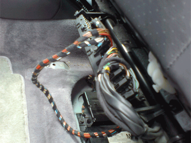
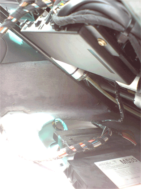
has anyone got the pin outs for the multiplugs on the facelift 996 instrument cluster. ive got the same workshop manual as most probably everyone else and it only shows wiring up to 2000. did the pin outs change on the later panels or were they the same and the cluster itself was just different. i dont want to start poking about with the loom until i know ive got the wires correct.
-
thanks loren, i was hoping that somewhere it showed replacing the cables from their pivot wheels inside the pedal housing itself. that diagram from the PET doesnt show info in the internals of the pedal housing where all the cables actually connect. i do have two cables on mine, i assume the top one goes to the cruise control module, each sits on a 1/4 circle wheel and its these wheels im not sure ive put back in properly. i watched carefully when removing to aid reassembly however theres a plastic tab on the main accelerator cable wheel that acts against the uppper cables wheel that i couldnt see until i took everything out and its this tabs location that has me concerned. theres not a location for it, it seemed to only fit above the upper edge of this secondary (upper) cable wheel so that the throttle cable being pressed turns this cable wheel also, however while this would seem to be right both in terms of fitting and operation not being 100% isnt filling me with confidence.
-
anyone got any info showing the inside of the accelerator pedal with respect to changing the accelerator cable on a non e-gas C2. i just had mine off and am now doubting myself ref the reassembly of the internal pieces of the accelerator pedal. mine has two cables into it, one from the top and one out the bottom. each sits on its own 1/4 circle piece and its the relationship between these two pieces thats troubling me with regards how ive put them back. if you know where this is in the workshop manual then that would be great as i can look it up. ive looked and looked and cannot find it anywhere but cant imagine its not there somewhere.
-
ive got the workshop manual and am about to embark on removing my whole sunroof mechanism (ie sliding portion, frame, motor etc) but just wanted to clarify some points if anyone has done this. if im taking out the whole lot can i just remove the interior roof lining and then pull the lot in one go by unbolting the frame or does the sliding portion and the motor need to come out individually first. it may all become obvious when i get a look inside but it would be a great help if anyone already looked at this and had some info to share.
-
loren, thanks. ill check again in my manual and see if i can find the relevant section. ehm.......yeah. its there in the manual hidden under the heading "3.4 engine x51" which explains why i couldnt see it when i looked haha. now thats embarrassing. id looked right through the lubrication section but didnt think it would be at the start next to torque info. thanks for the direction. ill get a read over it and see what it says
-
guys, been looking into the X51 oiling setup for the 3.4 engines, the one where the head scavenge pump is replaced with a dual pump and a line to the far corner of the head to allow pooling oil to be collected from here also. ive only got limited info on this ie part numbers and a one page drawing from porsche showing how it routes. does anyone have any definatives on this or other info. from the various things ive found on the web and from the drawing it looks like it only fits to the one side of the engine, on the right, however given that the overall engine design is symmetrical im wondering if it should actually be applied to both heads and im missing the text portion stating this. why would it pool only in the corner on 456 side and not on the 123 side when each side is essentially a mirror image with its own scavenge pump? any info anyone has would be great. i couldnt find the TSB for this and the workshop manual doesnt cover it either. loren, if you can share your wisdom id be much obliged.
-
my current info is that the GT3 LSDs will fit into the C2 box fine. this would put the cup diff at the top of my list though with the extra preload i wonder if it may be overkill somewhat. going with the GT3 option knowing that i can get it built with motorsport plates may be a better process. i'll post back as i get some definites through. ATB type diffs can be great, my feeling is however less so in our rear engined RWD configuration. they dont work under braking and this is when the weight is lifted from our wheels. with FWD braking puts the weight over the driven wheels which should make slipping less likely and thus reduce the need for a diff under this state. since im going to track alot i really need a solution that will work here aswell as on the road when required and this is making me favour plate types. guard make great units so this might also be an option thats for sure. no option seems like it is going to be cheap however. ive got my box out doing some other work anyways so atleast i save on labour more or less. i'll post more as i get some definates on this however
-
anyone know if this is possible? the physical mounting itself wouldnt be too tricky, just a few bracket swaps i expect, its whether things will mount up at the bellhousing end with the engine that concerns me. im assuming that the G96 from the C2 etc uses a different bellhousing pattern than the G96 used in the GT3 and the likes. it would make sense that this will be like that of the older G50. its one of those things that a 10 second look at one of each off a car would let you know in a flash but without either here im left in the dark asking questions that are no doubt about to make me look stupid.
-
really want to put an LSD into my car as the final mod. i really feel i need one since i track quite a bit now but im stumped over the options available to me. the obvious solution is putting the optional M220 diff into the car however it seems somewhat lightweight (22/40%) and i cant find any specs ref the friction plates and whether there are motorsport alternatives available to put into this to change its ratios. while i go over things i'm left with some questions: does anyone know anything ref the diff that comes with the M220 and can you get it built with motorsport type plates to get it set to something that would be more useable (40/60%). is it essentially just a softened version of the same diff porshce use on all their cars? will the LSD from the GT3 boxes fit in to the regular C2 box? anyone fitted an LSD with good results. what options are there. im not sure Guard offer one for the C2 box and Quaife is an ATB type diff rather than the clutch type. im not sure how i feel about using an ATB in a car i do intend to track atleast once a month. if anyone has anything to share that would be great.
-
anyone got any more info in this mod? i ve heard from a few people that turbo/GT3 mk1 brakes will bolt right on to the C2 hubs both at the front and the rear. you need to get non turbo rotors for the front and there will be an offset issue using turbo rotors but apart from that its plain sailing. several people who track have said they have done it without any need for spacers or issues but i cant get anything more from them. unfortunately there seems to be a lot of posts everywhere with everyone saying that you need to change hub carriers so i dont know what to believe. can anyone post anything definative, from their own experience with trying to mount reds onto a C2 using the stock carriers. i'll probably grab a set next week and have a look see myself but in the meantime anyone with direct experience feel free to chime in.
-
thanks, i actually dont have xenons though, only regular halogens. does this still hold for the halogen versions just ignoring the pins for the stepping motor?
-
having an electrical niggle that im trying to get to the bottom of and it would be a great help if anyone could give me the pin outs for the headlight connector for the regular halogen lights so i can see where the loose connection is. i have the same workshop manual most of you have and it only covers wiring up to 2000. not a huge help :) the connector has 12 pin allocations, if anyone could jot me down the number of each one (i guess theres ground, low beam, high beam, turn, fog feeds) used and what it feeds it would be a huge help. if each side differs (cant see why) if you could let me know too that would be great.
-
guys, looking for some definatives on swapping out the front sway bar on a C2, i might be looking in the wrong places but there doesnt seem to be much in the way of detailed info. its obvious when looking under the car that theres a retaining plate with three bolts that clamps it in place but that this plate also holds the mount for the front arm. im fairly experienced when it come to repairs and work on cars but ive looked several times and cant decide if the plate is simply providing a clamp for the bar and an attachement for the arm and therefor the only weight and forces involved are the physical weight of the plate itself or whether theres torsional forces here and unbolting will cause it to pop out or off, perhaps with some force is it as simple as it seems, just jack up, unbolt three outer bolts and remove bar and reverse? as a result im loathe to just start on it with a socket. im sensing the lack of info about means its as straightforward as it seems it could be and im simply over-engineering but if anyone could share their experience i would be much obliged
-
thank you both for the replies. im sort of flying blind as im back in the UK after visiting my parents for christmas. I head back to USA next week. i dont have any of my literature etc with me so am operating from memory mostly just now.....with a huge feeling off guilt after suggesting the purchase and glowing about my own car. their car is a UK spec 2002 C4 and was operating fine but has now just taken a turn it seems, sadly pretty much as soon as we got it home. it will all get sorted im sure as it was dealer bought, my own thoughts were switch too, its just with it being a weekend and me heading away next week im sort of wildy trying to diagnose for them before they condemn the car and to appease my own internal guilt lol. update...... im getting 12v across fuse A5 (im not sure how i didnt before) but nothing on that circuit is operational. they dont seem to have a common ground so that presumably rules that option out. the schematic shows the out from A5 going to BS10/1 term 58 and also splitting to weld point 35, also term 58. does this indicate a problem with the bridge point? im not even sure what the function of these are other than relay related. as you can tell im not an auto electrician however i am an engineer so can usually make out most things. this common mentioning of term58, which is the headlight switch positions I and II has me slightly confused though since it appears all over the place in relation to the drawing im working off im not getting 12v across fuse A9, but am across fuse A10. this headlight is working and the one from A9 isnt (surprise surprise, so perhaps switch is for sure the culprit here)
-
thanks for that. are you sure about the rear fog lights though? my us spec has two (well i think though im now second guessing myself) and this one for sure has two bulbs fitted up, one on each side though its entirely possible that its there but left unoperational thats for sure. im getting side lights, tail lights and headlights etc all working fine, though ive now got the left side dipped headlight also not operating....again with fuse and bulb fine. would this be pointing to an issue all with the switch?
-
my folks just picked up a 2002 C4 after me bigging up my 996 and its taken a funny electrical turn. basically its lost illumination to the dashboard, internal switches etc, the rear plate lights dont work and the rear right fog light stopped working too. now i know everything except the rear fog light runs from the same circuit but im trying to look at the wiring diagram to see if i can find any common point that may be a potential to investigate. i only have the schematics for the 1999-2000 models though and am unsure if there were any significant changes so am sort of hampered. if anyone can pm me a pdf or give any suggestions that would be great. by the way its def not the fuse :) its cold and wet here so maybe damp has gotten into something? its weird that they were all working fine and then just stopped, came back on briefly and then nothing since
-
thanks for taking the time to reply. i guess my understanding of the adjustment and what it actually did was slightly off. from just looking at the adjustment procedure i had im my head that moving from hole to hole added increasing levels of preload to the bar thus stiffening up when infact the increased stiffness if a function of reduced bar length/less leverage and not a preload issue at all. i guess the small distance between holes and the axis on which the drop links rotate actually back this up now im looking at it from the other end. thanks also ref the removal confirmation. it had to be too good to hope for that it would be as simple as the rear haha
-
just about to fit up my GT3 front sway bar but have a couple of quick questions. using adjustable drop links which hole should be used when setting the length? i cant decide if i should use the standard (middle) hole as the benchmark for no preload or the softest hole. anyone got any info. it would seem like it should be the softest so that all adjustments onwards use pull as the force. using the middle would give a combination of pull on as you harden and push as you soften. this doesnt seem correct from an engineering point of view but cars often dont :) second question is concerning removing the bar itself. do i need to undo all the suspension gubbins to get the front out. the rear is a simple clamp while the front looks attached under a plate holding control arm mounts etc. id hate to undo all of this only to find id missed something spectacularly obvious.
-
ok, with the help or loren (thank you once more) i got the seat out and the GT3 one in and all is great. the unit in the photos attached to the underside of the seat is indeed the brains for the memory option. if you have this and are swapping out for a GT3 seat just undo the two connectors feeding this. one is blue/white and removes by simply squeezing the securing clip, the other is white and requires a locking mechanism to be freed before it can come out. its black and across the middle of the connector. just lever it up with a screwdriver and once it is extended fully the connector will slide out easily. if it doesnt check you have the securing clip fully out. the unit then comes out along with the seat itself. proceed as per the DIY by separating the other common connector which includes the seatbelt recepticle wiring and remove the seat. only the seat belt wiring needs fitted with the GT3 seat. the two other connectors can just be secured to the floor. with the memory brain out, all memory functions will now cease to operate, this includes mirrors though mirror operation is unchanged.
-
heres some quick pics to show...

-
hi all, im midway through a seat swap putting a gt3 seat into my MY99 C2. i thought i was all good to go however now the seats unbolted and lifted up ive alot more wires than in any of the DIY write ups, i guess because i have power seats with memory (no heat or lumbar though) theres a black plastic box at the front under the seat and directly attached to it with three power connectors going into it branching off from the same loom as the regular/main connector shown in all the DIYs (with the seatbelt plug) and then a bunch of wires out all going to the seat itself. i assume these feed to the motors and are probably for the memory however in light of the fact that im not 100% ive ground to a total halt. can anyone advise if its safe to remove these connectors at the seat end and just tape them up under the seat? im not going to get a whole host of warning lights by doing so am i?
-
thanks for the info. does this apply then to the reds from the 996 turbo too i assume? would i come up against issues with discs/rotors fitting onto the exisiting hubs. what is the usual upgrade route with the 996 brakes. in the old days you could just stick on everything from a higher spec with ease more or less. thanks for the link joel.
-
anyone got any info about upgrading the regular black brakes to a set of reds from a GT3/TT at the front. is it a simple swap over with new rotors and pads to match the calipers or do you encounter problems that need the hub swapped, adaptors made and or ABS sensors and bias changed etc etc. i had a look over the internet but couldnt find any info sticking within the 996. i assume this is because people upgrade to brembo or similar bypassing these but i want to keep the stock look.