Welcome to RennTech.org Community, Guest
There are many great features available to you once you register at RennTech.org
You are free to view posts here, but you must log in to reply to existing posts, or to start your own new topic. Like most online communities, there are costs involved to maintain a site like this - so we encourage our members to subscribe or donate. All subscriptions and donations go to the costs operating and maintaining this site. We prefer that guests take part in our community and we offer a lot in return to those willing to join our corner of the Porsche world. This site is 99 percent member supported (less than 1 percent comes from advertising) - so please consider an annual subscription or donation to keep this site running.
Here are some of the features available - once you subscribe RennTech.org
- View Classified Ads
- DIY Tutorials
- Porsche TSB Listings (limited)
- VIN Decoder
- Special Offers
- Paint Codes
- Registry
- Videos System
- View Reviews
- and get rid of this welcome message
It takes just a few minutes to register, and it's quality Porsche information at a low cost.
Contributing Members also get these additional benefits:
(you become a Contributing Member by subscribing or donating money to the operation of this site)
- No ads - advertisements are removed
- Access the Contributors Only Forum
- Contributing Members Only Downloads
- Send attachments with PMs
- All image/file storage limits are substantially increased for all Contributing Members
- Option Codes Lookup
- VIN Option Lookups (limited)


niceguy
-
Posts
75 -
Joined
-
Last visited
Content Type
Profiles
Events
Forums
External Paint Colors
Downloads
Tutorials
Links Directory
Collections
Classifieds
Store
Everything posted by niceguy
-
Toyota test done according to p.14 of 21 1 man operation so readings at idle with ac and headlights Results open circuit - insulated side = 0.33-0.40 ( avg 0.35) Ground side = 1.20-1.52 ( avg 1.35v)
-
Results Cold engine Test A 0.22v Test B 1.45v Will now do Toyota tests n report
-
Thks fir the confirmation. I m home now working on my car. I guess the jump leads creating the extra ground did not work because those leads did not allow sufficient amount of current to flow thu them. I will do the Toyota tests n test b and report back in approx 20 mins
-
Oh, I am so sorry for my stupidity. I will do that right away and report back in an hour or so when I get home to my car. Just curious, what if both of them are at 0v meaning #28 and #36 are fine? Will Test C be? Put the black probe on the "+ve alt terminal" and the red probe on the "+ve transmission terminal". Again, it should read very close to 0v if #24 is in good condition. I am not good enough to remove things in order to reach the starter. Will that limit my testing ability to finding the ultimate culprit?
-
Thanks Ahsai for your replies!! I will carry out the amp measurements tonight and report back the readings. But, I'm sorry for my stupidity that I do not understand what I have to measure for the following - voltage drop between alt +ve terminal and engine +ve terminal (#29) - this will verify #28 - voltage drop between alt casing and the airfilter bolt - this will verify #36 Am I supposed to measure voltages for the following? 1. engine on 2. a/c on, heading lights on, +ve alt term to -ve alt case (I measured it and it was = 14.0v) 3. a/c on, heading lights on, +ve engine term to -ve alt case (=13.9v) 4. a/c on, heading lights on, +ve alt term to -ve airfilter bolt (measured = 12.1v) 5. a/c on, heading lights on, +ve engine term to -ve airfilter bolt (12.1v) The voltage drop between alt +ve terminal and engine +ve terminal (#29) = 0.07-0.10v, this verifies #28 is normal. But, the voltage drop between alt casing and the airfilter bolt =1.8-1.9v, this verifies #36 has a problem. Moving upstream towards the battery, should I measure the Volt between +ve transmission term to -ve engine case the Volt between +ve transmission term to -ve chassis near the ground strap I have the Vdrop result for this too and it is exactly 14.0v with engine case but 12.1v with chassis near the ground strap. Does these Vdrops mean my problem is in the engine chassis strap, no. 36? OR I have done it incorrectly, please advise me if I am wrong. Thanks again for your help and assistance. James
-
Thanks a lot jpflip!! Your info are great, I will try to remove the air pump to reach that bolt of the engine/chassis ground strap. Is there any danger in removing the air pump and the engine oil filling tube? What setting should I use on the multimeter in order to measure the power consumption at rest which is suppose to be .6 amps maximum? But, I dare not lower the engine because I am really very weak with DIY jobs... respect to all those help and advice again :notworthy: :notworthy: :notworthy:
-
I plan to have a go in replacing the chassis ground over the weekend. I am rather weak at DIY. The best I managed was to replace the alternator with my limited tools. Could you please advise what other tools I will need to remove enough in order to reach the chassis ground? First, I tried searching on the Internet for 30 mins but did not find any post about how to DIY removing the engine/chassis ground on the 996tt. I can remove the airfilter box and the black y-shaped intake manifold but everything on the passenger side of the silver hydraualicoil bottle seems to be new to me. Do I have to remove the black engine oil filling tube? What are those components sitting below the engine oil filling tube that I will need to remove? Thank you very much for your reply and assists again :notworthy: :notworthy: :notworthy: James
-
Hi JFP, Thank you for your reply again. Do you think my problem now sounds like the chassis ground strap? Can I go ahead and replace it with two 4 guage cables and try if it solves the problem before ordering one from the factory? Is there anywhere that I can add more chassis ground strap to the engine and chassis? Will it bring any benefit to the seemingly small stock chassis ground strap?
-
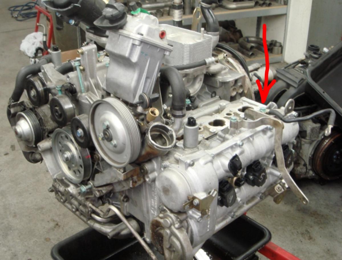
Hi JFP, Thanks a lot for your informative reply :) I think I might have made a big mistake in my original post. The resistance across all those no. 1, 4, 24, 28, 17 and 19 should be 0.07 Ohms, not 0.7 Ohms. It is because before I started the 4 tests that I conducted, I measured the resistance of my newly bought three-meter-long 4 gauge cable and the resistance was the same as all those in the car, almost close to none. I know it would have been better to have measured each cable end disconnected, but I simply do not have the skills and knowledge to take each of them out. But, however, I did disconnect no.1 (battery -ve lead) and no.24 (alternator to starter lead) to measure resistance on their own and the results were the same as those measured connected. My main point is that with the engine running at idle with full load (a/c on, all lights on), I did still see the full 14.0v when I measured from the back of the alternator to -ve alternator case, engine case, transmission case and fuel filter case whether the engine was hot or cold. The only time I saw 12.0-12.8v was when I measured the back of the alternator to the car's chassis, such as the airfilter bolt, the actually chassis, the cross member under the car and the silver door latch, all only showed 12.0-12.8v. I think I located the engine to chassis ground, no. 36, and the reason why I did not have any measurement for that was because my hands and tools could not reach it even with the wheel off and car on jack stand. But, I could see about 1/3 of that cable's plastic shield had been sliced open for some unknown reason. Does this sound like a bad engine to chassis ground to you? Moreover, my car starts every time and the engine turns quickly every time. Could you advise if no. 36, the engine to chassis ground is the one shown in the attachment? If so, how can I get to the top of engine bolt of that ground cable from under the car? Or, can I only approach it from the top without lowering the engine? I am a DIYer with limited tools at home and at where I live, there is no shop that will bench test my new and old alternators. Thank you very much for your help again. James

-
I believe I read somewhere saying that if you bench test your alternator and there is Vdrop as it gets hotter, the voltage regulator (removable & changable) is the problem. Voltage regulators do wear over time.
-
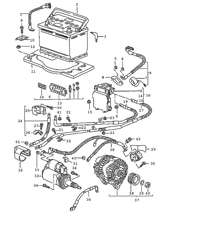
Having spent hours of research and jacking the car up and down, I will call this my last report because I've had enough of test car and that’s it if I still cant get it fixed by next week. Last night, I carried out the final voltage and resistance tests with cold & hot engine using the multimeter based on the 996tt electrical diagram attached. Let me list out the possible problems with my low voltage symptom. 1. 85A battery (new) 2. Bosch alternator 997-603-012-06 TIP (new) 3. regulator & alternator pulley (new, comes with item 2) 4. alternator to starter hardness 996 607 03 204 (no.28 ) Test 1 5. engine ground strap 996 607 034 01(no.36) Test 2 6. –ve battery lead 997 611-090 00 (no.1) Test 4 7. +ve battery lead 996 612 090 09 (no.4) Test 4 7. long cable from starter to ECU 996 612 044 00 (no.19) 8. engine terminal to transmission terminal 996 607 033 02 (no.24) So I focused on testing on no.24, 28, 36, 1 and 4. Not, 19 because I cant actually see it. According to the diagram, I assumed no.29 = +ve engine terminal and no.25 = transmission terminal. Test 1 (to prove alternator to starter hardness no.28 is OK even with the engine HOT) With the car hot or cold, battery +ve & -ve unhooked Resistance @ 200 Ohm setting +ve engine terminal (no.29) to +ve transmission terminal (no.25) = 0.7 Ohm +ve engine terminal (no.29) to +ve battery lead (no.4) = 0.7 Ohm +ve transmission terminal (no.25) to +ve battery lead (no.4) =0.7 Ohm -ve airfilter bolt to –ve battery terminal lead (no.1) = 0.7 Ohm -ve airfilter bolt to –ve chassis /door latch= 0.7 Ohm -ve airfilter bolt to –ve Hydraulicoil body/engine/gearbox/alternator case = 0.7 Ohm –ve Hydraulicoil oil body/engine/gearbox/alternator case to –ve chassis = 0.7 Ohm Voltage +ve directly from alternator (I fitted an independent lead from the alternator) -ve Hydraulicoil oil body / engine / gearbox / alternator case =14.0v (hot/cold) +ve directly from alternator -ve airfilter bolt / chassis / door lock =12.2v (hot) or 12.8v (cold) +ve transmission terminal -ve engine / gearbox / alternator case =14.0v (hot/cold) +ve transmission terminal -ve airfilter bolt / chassis / door lock =12.2v (hot) or 12.8v (cold) Results 1. Voltage always 14.0v if –ve are measured from engine/gearbox/fuel filter casings. Voltage always 12.2-12.8v if –ve are measured from chassis (airfilter bolt/door latch/chassis metal). 2. But, resistance of no.28 is the same hot or cold, it seems to be in good order. No.28 seems to be fine and the problem seems to be on the chassis ground. So, I conducted Test 2. Test 2 (to test engine ground cable, no.36) Hooked up 2 thick truck-grade jump leads from engine case (-ve) to chassis (ground) and door latch (ground) = nothing happened to all voltage measurements (same as unhooked) Cold measurements, idling At battery 12.9v (cold) On dash voltmeter 12.9v +ve engine terminal to airfilter bolt 13.2v +ve directly from altern. to altern. case / Hydraulicoil oil tank body / fuel filter 14.0v Hot measurements, with aircon and headlights on: batt multimeter 12.1v (hot) dash voltmeter 12.1v engine terminal 12.4v alternator terminal 13.9v Results Adding extra engine to ground leads did not do anything or helped the stock engine ground cable. So, no.38 is in good order, too. Test 3 (to test no.17 & 19) COLD voltage +ve alternator terminal to airfilter bolt (chassis ground) = 13.2v +ve batt to –ve batt = 12.9v HOT voltage +ve alternator terminal to airfilter bolt (chassis ground) = 12.4v +ve batt to –ve batt = 12.1v Results No.17 & 19 are using or losing 0.3v because there is always a 0.3v difference between the back of the engine to the front of the car. I can say theses 2 long cables are in good order because how far voltage has to travel here. Test 4 (to test no.1 & 4, hot and cold engine) Took them off the car, measured resistance before cleaning them and they never got hot even after 30 mins of driving. Always 0.6 Ohm Results No. 1 & 4 are in good order. It seems to me all the cables are in good order. Who can help me to solve this my low voltage problem? a million thanks James
-
Having replaced both front sway bar drop links with the TRW units, the knocking and vibration felt through the steering wheel is now completely gone. I am happy to report that with around 30-40k miles these units can fail and I did find some vertical play in the bushings.
-
Thank you very much for your insightful and experienced answer, Loren!!! I will make the marking on the tire and rim tonight. But what if I dont plan to do any more launches for a while? Is getting the wheels balanced again the only cure to this tire-related strange vibration? James
-
Having had the wheel balancing done for all 4 wheels, I went for a test drive and the steering wheel vibration at 100kph was gone. But, sadly, it is now vibrating at 110kph or so. The strange thing is that after some spirited driving, the car vibrated more than it did normally and the vibration now seems to be shaking the whole car at 110kphph quite badly. Could this be an engine or gearbox or suspension related problem? Even more weirdly, the car has been back to perfect with no vibration at various speeds in the past 2 days. But, I didnt go into boost since the shaking to avoid any damage to the turbo or engine. My noisy front anti-roll bar drop links are still not replaced. And, I am really worried Could the sticky weight used in the inner wheel for the balancing job be loosened by the heat during the spirited run? All I did was 3 launches from lights to stop. Would anyone please help to diagnose this problem?
-
Hi tphss, My car has done 37500 miles. The noise from the drop links started from early 30000 miles. Now, I have a choice to replace them with the TRW drop links but my local indy said the noise will come back quite soon due to a design fault. Yet, the drop link are still 100% functioning perfectly with only some undesirable noises.
-
white Steam rising from centre n driver radiator 996tt
niceguy replied to niceguy's topic in 996 TT, 996 TT S, 996 GT2
Problem solved Having removed the bumper yesterday, I found there were loads of leaves n dust stuck to the radiators, which is exactly what i thought what it might be. To confirm my finding, I left the bumper off after cleaning the radiators, clearly i could see smoke coming out of the front (mouth) n the 2 radiators on the side. Once dried, there were no more steam, thank god. So, this the steaming issue should be the same for all 996 models and the smoke should only appear in the wet or when the radiators are wet with no loss of coolant. -
white Steam rising from centre n driver radiator 996tt
niceguy replied to niceguy's topic in 996 TT, 996 TT S, 996 GT2
2nd update of the problem, 1 no loss of coolant 2 steam appear only in wet weather 3 in dry weather, the radiators do not even feel hot when I put my hand into the grills of the front bumper (not sure if the condensers are in the way causing the inability to feel the heat) I plan to remove the bumper tonight to inspect for any leak and remove the dirt stuck between the condenser and the radiator. Moreover, the abs & Pam light always reappear at the same slope (decline) in the car park when the car is still cold. V Minor engine rev fluctuation can be felt at idle. It drives like a train otherwise. -
white Steam rising from centre n driver radiator 996tt
niceguy replied to niceguy's topic in 996 TT, 996 TT S, 996 GT2
I hope it is just some curd or turd or tissue paper sticking onto the radiator. I plan to remove e bumper myself but I am worried with my limited skill, I might damage the paint on the bumper in the process. -
white Steam rising from centre n driver radiator 996tt
niceguy replied to niceguy's topic in 996 TT, 996 TT S, 996 GT2
An update of the issue of my 996tt, it didn't lose any coolant according the level of coolant bottle in the engine bay and no steam is coming out from the from drive side radiator as well. I only noticed the steam after rain or a car wash. Furthermore, the coolant temperature wasn't 90-95C. Instead it was only 80-82c or so. To sum up, 1 no coolant loss 2 no steam in the dry (even after some driving n idling) 3 coolant temp 80-82C 4 that steaming radiator was replaced in 2009 -
The steam can be seen when the car is parked with the engine still running. It can't be seen when the car is moving tho. The dash coolant temperature gauge remains normal at around 90 - 95 degree celsius.
-
Thanks EleCTriCT for your information.My local indy told me that the stock Porsche drop links have a flaw and therefore, the clonking noise will come back after a year or so even when new units are replaced. That's why I asked if the TGW units are better. As soon as I am driving with the steering wheel turning, all the clonking noises are gone. Does that mean it has to be the drop links that are making the noise on my tt? Cheers
-
Thanks fly2low2 for your recommendation. I have also read a few positive reviews on tarett drop links. But, I'm just find them a little pricey for my car especially when only have stock suspension on it. Would the TRW be fine for another year or two?
-
Thanks for all the advice!! I am quite certain the drop links are the culprit of the noise and possibly the lower wishbones making the v light creaking noise. Has anyone tried the K sport drop links? Oh yes, and they are adjustable too. Will they last better than the stock's thin and skinny drop links? I am on fully stock suspension. Link to these end links http://www.ksportusa.com/asp/endlink...roduct_id=el01
-
Thank you very much for the confident you have just inspired on my 00 996TT. Mine has just done 40000miles. But the Tip gasket leak just cannot be fixed by the local indi
-
Thanks kosmo96 for your sharing. Was it the sway bar drop link that you had to tightened? or was there something else?