Welcome to RennTech.org Community, Guest
There are many great features available to you once you register at RennTech.org
You are free to view posts here, but you must log in to reply to existing posts, or to start your own new topic. Like most online communities, there are costs involved to maintain a site like this - so we encourage our members to donate. All donations go to the costs operating and maintaining this site. We prefer that guests take part in our community and we offer a lot in return to those willing to join our corner of the Porsche world. This site is 99 percent member supported (less than 1 percent comes from advertising) - so please consider an annual donation to keep this site running.
Here are some of the features available - once you register at RennTech.org
- View Classified Ads
- DIY Tutorials
- Porsche TSB Listings (limited)
- VIN Decoder
- Special Offers
-
OBD II P-Codes - Paint Codes
- Registry
- Videos System
- View Reviews
- and get rid of this welcome message
It takes just a few minutes to register, and it's FREE
Contributing Members also get these additional benefits:
(you become a Contributing Member by donating money to the operation of this site)
- No ads - advertisements are removed
- Access the Contributors Only Forum
- Contributing Members Only Downloads
- Send attachments with PMs
- All image/file storage limits are substantially increased for all Contributing Members
- Option Codes Lookup
- VIN Option Lookups (limited)


Iceyankee-Tsi
-
Posts
32 -
Joined
-
Last visited
Content Type
Profiles
Events
Forums
External Paint Colors
Downloads
Tutorials
Links Directory
Collections
Store
Everything posted by Iceyankee-Tsi
-
Hi 911 Rod: I agree with Jpflip on this. It is something pretty common with 996 turbos for the clutch slave to go bad. It happened to me on my old 996tt. It will be very clear to you if you look at the clutch reservior under the hood that is probably overfilled and leaking. The GT2 Slave solution is the best way to go. It will provide a slight increase in pedal pressure effort and it will cost a bit higher that just replacing the stock salve but gets rid of this problem that repeats quite often. Best of luck!
-
Car Cranks but Doesn't Start
Iceyankee-Tsi replied to Iceyankee-Tsi's topic in 996 TT, 996 TT S, 996 GT2
Hi Superboyg: Sorry to hear this is happening to you. I can tell you that after replacing the plug and insuring all the wires were properly connected to the fuel sender plug, evertything worked fine. My assumptions are the following in my old case: A poor connection between the fuel level sender and the plug in addition to the high Amp draw of the old fuel pump(maybe due to a deffective pump) created an overheating condition in that area that made the wire start to melt. Like I mentioned in the previous posts, when I replaced the pump with a walbro unit, the change in wire temperature was considerably noticeable. Hence, I would suggest to change the plug, insure proper connection between the fuel sending unit and the plug. If this doesn't work, replace the pump. That would be the path I would follow. I no longer have my 996 Turbo, yet after this was done I've never had to mess with it again. If I can be of any additional help, please feel free to let me know. Good luck sir! -
Greetings Joel:
I am afraid not my friend. To be honest, since I troubleshoot all the electrical parts of the car(solenoids, etc), At this point I understand that this issue is mechanical. Probably related to a bad variocam mechanism(the timing sprocket). For this I will have to lower the engine and disassemble it to replace the unit and/or find the defective part in that engine se...
-
Car Cranks but Doesn't Start
Iceyankee-Tsi replied to Iceyankee-Tsi's topic in 996 TT, 996 TT S, 996 GT2
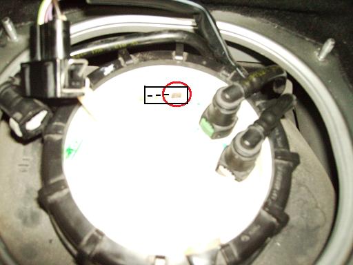
I verified the diagram and the plug is not there. It seems that some VW/Audi supplied parts are not included in the manual. The part number for this plug is 357 906 231 and has the VW/Audi symbol stamped in the side. I looked at Rector Motors web page and it has a list price of $6.20 which is reasonable. However, I wonder if it includes the pins where the cables are crimped to or if I have to purchase them separately? I guess I would need to call to find out that one. Regarding the fuel pump test, thanks I read that info while looking across the manual for the fuel pump. That would be the appropriate way to test fuel flow. Since I am using at this time a Walbro 255 ltr/hr high pressure fuel pump, I understand everything is running as it should. For some reason, i don't think that the stock fuel pump can flow more than this. However, this is just speculation since the stock pump I have doesn't have any part number or inscription(other than the VDO letters) that I could use to identify its operation characteristics. That would be a great piece of info if somebody has it. :thankyou: Andres -
Car Cranks but Doesn't Start
Iceyankee-Tsi replied to Iceyankee-Tsi's topic in 996 TT, 996 TT S, 996 GT2
ja ja ja. Thanks for that JP :D : Well, to start off my car did'nt want to start. The answer to this one is that probably due to overheating of the fuel pump ground cable, its contact to the car's ground was lost. Hence, not allowing the engine to start due to lack of fuel. After I wiggled the brown cable a little bit, the car started. Since this was the only thing I did prior to the engine starting and since after it has started every time, I understand that was the problem. That brought me to find out the problem regarding the overheating ground cable. It seems that the cable mod I made worked pretty well since even though the cable is not completely cold, it gets warm to and acceptable level. What I mean with that is that I know it is not capable of melting nothing. However, do any of you know if this fuel pump/level sender plug is sold separately that I could purchase and reconnect the wires the right way? It is not that I like to have a car like this looking like a project car. :) Thanks, Andres -
Car Cranks but Doesn't Start
Iceyankee-Tsi replied to Iceyankee-Tsi's topic in 996 TT, 996 TT S, 996 GT2
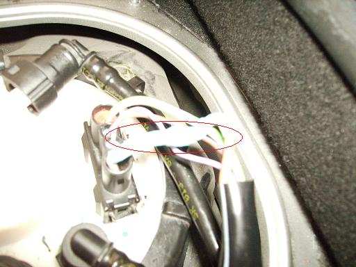
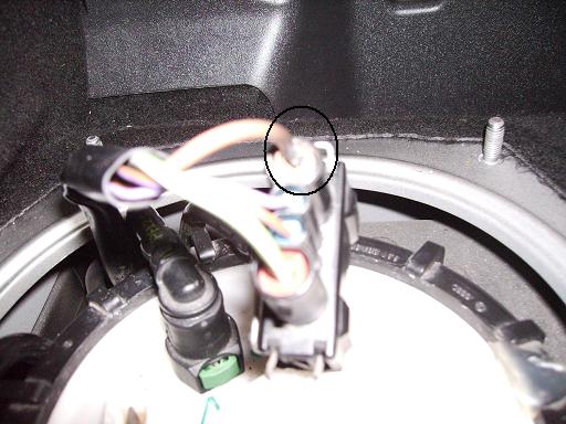
Okay guys: Let me tell you what I have found. First off, let me explain in better detail what I previously said. As all of us can see, there are two cables that connect to the fuel level sender that go to the fuel pump. These are the green cable with the white stripe(which is the pump's 12 volt source) and the brown cable(which is the pump's ground). What I did was to measure the resistance of the green cable. The lecture was of 6.5 amps. After posting this message I went disconnecting fuse by fuse until I found the fuse that was creating that resistance in my green fuel pump power cable. I found out that there was a 5 Amp fuse connected in row C5 that was creating this "mini short". When looking at the fuse diagram in the manual, I noted that this fuse slot was meant to be empty by the manufacturer. The only extra thing I see in the car besides the OEM stuff was a Passport SRX radar(which doesn't work). I may think that the previous owner used this fuse slot to power his radar. I left out the fuse and now with power off and green cable unplugged, I have zero resistance as it is meant to be. However, this may have been part of the problem but it didn't fixed it. The brown ground cable kept overheating. I went on and removed the brown cable lead from the fuel pump/fuel level sender connector. The contact area with the fuel level sender lead was pretty much fried. So using the same connector, I cut and removed the remains of the fried brown cable and soldered a new piece of wire with the same specs as the old fried brown cable to the connector. I then solder the other end of the new cable to the section of brown cable that went to the car(see picture and sorry for the quality). Left the car running for 1/2 an hour and the condition seems like it has improved(the brown cable goes a little bit warm but it doesn't get as hot as before). Can anybody confirm me is a 0.30 Amps current is reasonable for the pump operating in idle? This was the measurement I took from the brown cable with the car on. After all, I think I may need a new plug. Thanks. Andres
-
Car Cranks but Doesn't Start
Iceyankee-Tsi replied to Iceyankee-Tsi's topic in 996 TT, 996 TT S, 996 GT2
Well guys: No luck at this point. Tested the car with my Walbro 255 ltr/hr fuel pump installed in place of the OEM one and the brown ground cable overheated. I verified continuity against ground in the green/white cable which is the 12V power source to the pump and it measured 6.5 ohms!!! Isn't supposed to be zero? can somebody unplug their fuel pump/fuel sender electrical connector and check this reading for me please? At this point I think I may have a short somewhere but I removed the fuel pump fuse and the pump's relay and I still have 6.5 ohms in my fuel pump power cable. Is there a specific wiring diagram that may show me where do these two cables (the brown ground cable and the green with white stripe power wire) go from the fuel pump plug? I have tried to find it without luck. Thanks. Andres -
Car Cranks but Doesn't Start
Iceyankee-Tsi replied to Iceyankee-Tsi's topic in 996 TT, 996 TT S, 996 GT2
Well, At this point I think I have found a good way to sort this out. I will connect to the car's fuel pump harness a spare Walbro 255 ltr/hr fuel pump that I have from my 1991 Eagle Talon TSi just to see if the wiring overheats the same with this pump. If it does, I will know that I have to search for a short circuit,bad grounding, etc in the car. In the other hand, I will connect again the car's original fuel pump to a spare 12 volt source to see if the wiring overheats as previously happened. I guess that would be the final check that will prove a defective fuel pump. I will let you know my findings. Thanks for all your comments. Its great to have available all this wisdom and technical knowledge that you guys provide. Best regards, Andres -
Car Cranks but Doesn't Start
Iceyankee-Tsi replied to Iceyankee-Tsi's topic in 996 TT, 996 TT S, 996 GT2
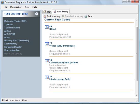
Alright guys: I am happy to tell you that I was able to start it up!!! :) However, I have a problem that needs to be solved. :( Let me provide the details. First off, I connected my Durametric tool to find out that there were no errors with the exception of the alarms attached. So I proceeded to check all the fuses. None was blown. I then started to manipulate the fuel pump relay with the Durametric and to my surprise the system sound like operating but the sound came from the back of the car!!! How come if the pump is in the front!!! Well, the answer to that is that it seems that for some reason when I activate that relay, other artifacts activate like for example the rear fan and the vacuum pump(both of them at low speed). Now, I went to the front of the car and unplug the fuel pump harness. I found curious that the brown cable(ground for pump) was like overheated and the plastic area surrounding its connection pin was melted. Humm!!! It doesn't look good. I attached some pics of what I found. I wiggled everything a little bit. Cranked the engine and.....surprise!!! Car was alive again. However, since I didn't like what I saw I continued monitoring the power leads to the pump(the brown cable and the green with white stripe). I noticed that as the car remained turned on, temperature was increasing to a point that is for concern. So in order to understand if it is a failing fuel pump or relays/fuse/short circuit related, I applied 12V straight to the fuel pump with its harness unplugged. The result was interesting, the cables I used started to increase their temperature which makes me understand that the problem is related to the fuel pump. Now my question is, lets say that for some reason I have a clogged fuel filter, could this increase the pump's work making it overheat hence overheating its power leads? I have always thought that these types of things were supposed to be captured by the fuel pump fuse. Have some of you heard anything related to a similar issue before? I verified that the fuel pump fuse was the correct grade and it is the right one: 30 Amps. At this point I may think on ordering a new fuel pump based on my testing but would like to know your opinion. Thanks, Andres
-
Car Cranks but Doesn't Start
Iceyankee-Tsi replied to Iceyankee-Tsi's topic in 996 TT, 996 TT S, 996 GT2
Hi WRoss996TT: I agree with you. Since I still haven't hooked up my scan tool after this issue, the first thing I will do is to check for error codes using my Durametric tool. I have an Actron Scanner which typically I use to clear my infamous P-1325 code since it is more handy than hooking up my laptop to clear it with the Durametric Software. But this is the first time that this happens to me. Is great to know that the "limp" mode will still allow me to startup the car, hence this discards the possibility of some relationship with the CEL clearance. In addition, since the car cranks, I understand that I can discard the clutch switch. If I recall correctly, I read your topic associated with the hose inside the gas tank that due to deterioration may release the fuel pressure. I will be checking this after the other battery of tests: fuses, relays, etc.. This could be a probable cause of my problem. I will let you know. Thanks guys!!! Andres -
Car Cranks but Doesn't Start
Iceyankee-Tsi replied to Iceyankee-Tsi's topic in 996 TT, 996 TT S, 996 GT2
Hi jpflip: As always, trying to help up. I really thank you and appreciate it. I will absolutely verify this. As I am at work right now and the problem was this morning, I haven't done no troubleshooting at all. Will post back with the findings. Best Regards, Andres -
Greetings guys: I am having a little trouble with my 2001 996 Turbo. First, let me state a known fact. For some time now, I am having a check engine light that gives the code P-1325 which is associated with the Bank #2 variocam system. Since I am pretty sure it is mechanically related, I have no plans to deal with it right now. Yesterday I used the car without any issues besides my common CEL. Last night as I am usually doing after dirving for I while, I clear up with my OBD2 scanner my CEL and left the car it alone for the day. Today when going to work, I got in the car and it didn't wanted to start. It does crank, but it doesn't start. Is there a possibility that after clearing several CELs without fixing the problem the ECU may enter in a "protection" mode (or something similar) until the fault is corrected? It may sound weird but since I didn't do anything else besides the CEL clearance, I don't know what else to think. Once I get home from work I will be checking for the basics. Ignition supply and fuel. Plus will connect the durametric to see if there are any codes. Any advice on what to check would be greatly appreciated. Best regards, Andres
-
Hi Sinister: Would you please show me which hose had this problem? Yesterday my car started fine and today it cranks but it doesn't start. Will like to see if everything is okay regarding gas. Thanks. Andres
-
OBD2 Fault Code P1325-Inlet camshaft bank 2
Iceyankee-Tsi replied to Iceyankee-Tsi's topic in 996 TT, 996 TT S, 996 GT2
Greetings jpflip: I'm afraid to tell you that I still haven't done nothing about it. I ended up having to purchase a new slave cylinder/accumulator and since I spended a few bucks on that, haven't been able to work out this huge issue. At this time I am holding up some cash to purchase the tools I will need for the job. These include: 1- P- 9653- camshaft sprocket release tool- $154.65 2- P- 9401- Timing Chain Tensioner-$289.00 3- P- 9661-Camshafts timing set blocks-$922.58 Total: $1366.23- To begin with. :( So this is gonna take some time. I assure you that even if it takes me a few months, I will be letting you know what was the cause of my problem. Best regards, Andres -
Greetings Whiteturbo: What they are talking about is the variocam actuator. This actuator is located in the intake camshafts of the engine. It forms part of the intake camshaft sprockets. In other words, both intake camshaft sprockets have integrated the variocam actuators. When disassembling and/or assembling the engine, the mechanic needs to set the camshafts to the original timing position with the engine in top dead center(TDC) using the special Porsche tools(these tools simply maintain the camshafts fixed in there proper position while pistons 1 and 4 are in TDC). Once this is achieved, using another Porsche special tool, the sprocket needs to be rotated counter-clockwise(stated as many as moving it to the left) to properly undo the main camshaft sprocket bolt. If this is not done, the camshaft when tightened will not be in its correct timing position even though the camshafts were fixed with the Porsche tools in there original timing locations. A good way to test if the variocam activate is working properly is to simply activate the system using a durametric system or with the engine in idle, simply applying 12Volts to the variocam solenoid of the bank that is suspected to have the problem. If the system is operating correctly, there should be a noticeable change in engine sound and operation when the variocam solenoid is activated. You can read the thread I started "Porsche code P-1325". There are some pictures that will illustrate what I am talking about. To be honest, I would not expect a mistake of this type in a Porsche certified shop since the service manual is very specific about this topic. Best regards, Andres
-
Hi everybody: The definite solution to the check spoiler warning in the dash for the minimum amount of 0 dollars with cero cents!!!! This is from my 2001 911 turbo and I understand it applies to all other 996 turbos since the system is the same. It all goes down to look for the appropriate switch combination that will fool the ECU to think that the spoiler is upward all the time at the spoiler ramp micro-switches. All this was performed in the spoiler-engine cover stock harness. I have attached two pictures. One illustrates the right spoiler ram assembly(looked from the rear). This is the ram that has attached two micro-switches. One of them has a blue cable and a black cable and the other switch has a gray cable and a black cable also. These switches do not perform alike. What I mean is that when one of the switches is depressed, it provides continuity between both of its cables. While the other switch opens its circuit. As seen in the second picture, I removed the assembly to show how it works. The little metal clip makes contact with the inner sleeve of the ramp as there are two cut-outs in the ramp that allows contact between the clips and the ramp sleeve.( There are two metal clips but i lost one of them today). When the spoiler is downward, these two clips(hence the switches) are pressed. This switch combination tells the ECU that the spoiler is downward. When the spoiler is fully extended, both clips are released and the switches as well. Hence, telling the ECU that the spoiler has been extended. In order to get rid of this spoiler warning for ever you will have to do the following: Simply simulate the position of the spoiler extended with the switches by disconnecting them from the spoiler ramp bracket and securing them in the released position. Or the same thing without the switches: 1- Make the gray cable and the black cable have continuity at all times. This can be done by cutting the cables from the switch and connecting them together. 2- Cut the cables from the micro-switch that have the blue cable and black cable and isolate them with electrical tape in order to prevent continuity from them. Finally, remember to disconnect the plug of the spoiler switch control in the dash, since as you may imagine if for some reason you press the "spoiler downward" option the warning will appear. This will happen since after a few seconds of the ECU not receiving the micro-switch combination of the "spoiler down" status it may think that something has gone wrong. I have done this today with absolute success. My testing included several 70 MPH pulls with no spoiler warnings. Hence, it is proven. Any doubts, just let me know. Best regards, Andres
-
OBD2 Fault Code P1325-Inlet camshaft bank 2
Iceyankee-Tsi replied to Iceyankee-Tsi's topic in 996 TT, 996 TT S, 996 GT2
I do think you are absolutely right. I have spoken with a Porsche expert here in PR about the problem and I will be waiting word for him between monday and tuesday. Depending on his answer and quote pricing, this idea of doing it myself will be a go. I will let you know the outcome. Best regards, Andres -
OBD2 Fault Code P1325-Inlet camshaft bank 2
Iceyankee-Tsi replied to Iceyankee-Tsi's topic in 996 TT, 996 TT S, 996 GT2
Well, Actually after looking at that buildup, I think that I would be limited to find a chain tension tool, the rear camshaft plates and the camshaft sprocket handle bar. The main idea should be to maintain all the original timing chain positions across the engine while been able to replace bank #2 vario cam actuator for a new unit if nothing else looks wierd when removing the camshafts cover. I may be missing something but I think this would be it. Andres -
OBD2 Fault Code P1325-Inlet camshaft bank 2
Iceyankee-Tsi replied to Iceyankee-Tsi's topic in 996 TT, 996 TT S, 996 GT2
Ja ja ja. It would be a pleasure to have you around JP!!! We can work something out if you wish. :) I admit that at this point I am seriously considering this as an alternative. The only thing that makes me hesitate is that I understand there are some special tools needed to remove the engine timing section required to make the vario cam actuator replacement. I definetly agree with you that there are a few alternatives to fix this up: 1. Oil passages to the vario cam clogged. Solution= cleaning throughfully. 2. Variocam actuator damaged, stuck, etc. Solution= unit replacement 3. Excessive clearance between the oil supply section to the camshaft and the variocam actuator. Solution= replace worn out parts. As you presented, I should expect to pay like $750 to $850 for a new vario cam unit. But for example, what tools I would need for the disassembly/assembly procedure in order to be sure not to screw up the engine timing? In terms of engine removal, the manual is not that detailed in the steps they suggest for removal. Any good site with pictures that could enlighten my path? Thanks!!!! Andres -
OBD2 Fault Code P1325-Inlet camshaft bank 2
Iceyankee-Tsi replied to Iceyankee-Tsi's topic in 996 TT, 996 TT S, 996 GT2
JPFLIP and Chuck: Nothing else to say that thank you for those encouraging and kind words. It is always a pleasure to have people with such a high level of empathy and willing to help another Porsche brother with their knowledge and good wishes. :) At this time I am in the process of talking to some of the known Porsche mechanics here in PR that may be able to quote me a reasonable price for the repair. Since the car is running and the engine is operating pretty smooth I guess I will use it occationally for short distances until I may be able to gather enough money to do the fix. I noticed that once the BANK #2 code check engine is lit, the ECU disables Bank #1 vario cam functions as well. So even though I may not have an operational vario cam system, I may still be able to use the car without pushing it. Even though, to be honest a check engine light is so annoying that I will try to fix it as soon as I can. I will let you know the conclusion of this novel. Best regards, Andres -
OBD2 Fault Code P1325-Inlet camshaft bank 2
Iceyankee-Tsi replied to Iceyankee-Tsi's topic in 996 TT, 996 TT S, 996 GT2
Well guys: At this point it is very sad for me to tell you that I made some additional troubleshooting and I have tracked down the problem to the variocam mechanical section of the system. I have gotten into this conclusion after been able to remove the camshaft adjustment solenoid(#23 in the PET) of bank #2. I made a special tool that worked just right for the soloenoid removal. The solenoid was clean and I had the chance to actuate it outside the engine and it did what it was supposed to do. Since I still had a little doubt, I then removed the variocam adjustment solenoid of bank #1, checked it, actuated it and both had the same behavior. Finally, I switched the actuators positions and assembled everything back. I started the engine and with the durametric, I activated the Bank #2 camshaft adjustment with no success. Of course I tested also bank #1(since I made a solenoid swap) and it activated as expected. To be honest, at this point I know that the engine needs to be removed and that at least bank #2 variocam actuator needs to be replaced or its oil passages need to be cleaned or who knows if it could be worst. :( I may be looking at some second and third opinions regarding the problem fix, but I have to admit that I am afraid to taking the car to any mechanic since just looking at a 911 turbo they see a huge money pit. This dream is starting to become a nightmare. l will let you all know how it turns out. Best regards to all, Andres -
OBD2 Fault Code P1325-Inlet camshaft bank 2
Iceyankee-Tsi replied to Iceyankee-Tsi's topic in 996 TT, 996 TT S, 996 GT2
You bet I did JPFLIP!!! I did 4 things: 1. Read the actual voltage sent to the solenoid with the engine at idle= 9.4 volts. 2. Applied 12 volts to the solenoid with the engine shut down- It does work.(It ticks) 3. Connected the durametric and actuated the camshaft adjustment feature and nothing happened. Even thought by measuring with my multimeter I could see that the DME voltage sent to the solenoid was oscillating between 9.4 and 12 volts. Which should make the solenoid work. But there was no change in engine sound. 4. Applied 12 volts directly to the solenoid with the engine working- No change in sound. Which takes me to the point of removing the solenoid and looking for dirt or obstruction in the solenoid orifices and/or its housing. However, this doesn't look that easy due to space constraint. Since I know the solenoid is actuating, this is the only possibility I see left. Of course I would like to switch the sides of the solenoids like I previously did with the camshaft valve lift solenoids, but bank 1 solenoid is out of sight and since it is already complicated to check bank 2 I guess I will have to decline doing it. Andres -
OBD2 Fault Code P1325-Inlet camshaft bank 2
Iceyankee-Tsi replied to Iceyankee-Tsi's topic in 996 TT, 996 TT S, 996 GT2
Hi JPFLIP: Thank you for those pictures and the link. I verified it and I have it completely visible from the engine compartment. However, I don't know how easy it will be to remove it. Now I need a way to test it. There is a way to test it and after looking at the solenoid's picture, I can see that it is quite possible that oil passages may clog, preventing the expected action from occuring. I will let you all know the outcome. Andres -
OBD2 Fault Code P1325-Inlet camshaft bank 2
Iceyankee-Tsi replied to Iceyankee-Tsi's topic in 996 TT, 996 TT S, 996 GT2
JPFLIP: You don't have an idea how much I wish you are right. However, is there any block of instructions on how to check this solenoid. I have the perception that it is more involved than sensor #23 due to accessibility. RFM: I will log all the values related to bank 1 and bank 2 available in the software at idle and post it in order to see if there is what we need for comparison. Thanks, Andres -
OBD2 Fault Code P1325-Inlet camshaft bank 2
Iceyankee-Tsi replied to Iceyankee-Tsi's topic in 996 TT, 996 TT S, 996 GT2
Greetings guys: First of all let me thank you for joining in because you don't have an idea of the frustration I am going through. I barely have put miles in this car and it makes me sad to think that I may have to send it already to a repair shop. Its always great to have people willing to provide their knowledge to help solve a problem. I really appreciate it. :) JPFLIP: Thanks for your comments. To my best understanding, solenoid valve #25 of bank #2 is the one that's creating my CEL. This is because with the Durametric tool I am not able to actuate it as I can with bank #1. And once clearing the P1325 code and trying to actuate bank 2 again with the durametric, It gives me the same code without any difference in engine sound. How ever, if what you are stating is correct, It is not a bad idea to check it too. Is there a specific way that it can be done or is it necessary to remove the engine to verify it??? :unsure: Just to clarify, I have only been working with valve #25. This means that if for some reason the correct solenoid to check is #23, I have been messing with the wrong solenoid all the time. To update, since I cant help trying to find out the problem, I disassembled everything again in order to make a simple test that I haven't done before: switching solenoid #25 from bank 1 to bank 2 and viceversa. First, of course I went and compare them physically and saw their specs and they were identical. So i proceeded. Unfortunately, forcing bank 2 with the durametric tool gave me the same results. Which now makes me think that the problem is in the engine. Why? Because even though I previously stated that when I actuated bank 2 solenoid by applying a direct 12 volt voltage to it, the engine sound wasn't similar to bank 1 when triggered. I am starting to be afraid that I have purchased a car with a hidden fault. :unsure: RFM: I know that I can see several data with the durametric tool. But can you tell me exactly what values are you mentioning and at what RPM's would be optimum so that I can run a log and post it? Thanks, Andres