Welcome to RennTech.org Community, Guest
There are many great features available to you once you register at RennTech.org
You are free to view posts here, but you must log in to reply to existing posts, or to start your own new topic. Like most online communities, there are costs involved to maintain a site like this - so we encourage our members to subscribe or donate. All subscriptions and donations go to the costs operating and maintaining this site. We prefer that guests take part in our community and we offer a lot in return to those willing to join our corner of the Porsche world. This site is 99 percent member supported (less than 1 percent comes from advertising) - so please consider an annual subscription or donation to keep this site running.
Here are some of the features available - once you subscribe RennTech.org
- View Classified Ads
- DIY Tutorials
- Porsche TSB Listings (limited)
- VIN Decoder
- Special Offers
- Paint Codes
- Registry
- Videos System
- View Reviews
- and get rid of this welcome message
It takes just a few minutes to register, and it's quality Porsche information at a low cost.
Contributing Members also get these additional benefits:
(you become a Contributing Member by subscribing or donating money to the operation of this site)
- No ads - advertisements are removed
- Access the Contributors Only Forum
- Contributing Members Only Downloads
- Send attachments with PMs
- All image/file storage limits are substantially increased for all Contributing Members
- Option Codes Lookup
- VIN Option Lookups (limited)


xmac
-
Posts
178 -
Joined
-
Last visited
-
Days Won
2
Content Type
Profiles
Events
Forums
External Paint Colors
Downloads
Tutorials
Links Directory
Collections
Classifieds
Store
Everything posted by xmac
-

changing out thermostat only?
xmac replied to RD996's topic in 996 Series (Carrera, Carrera 4, Carrera 4S, Targa)
I can confirm that the thermostat is replaceable without removing the water pump. The hardest part is twisting the thermostat to fit into the housing. I think they also sell the combo housing + pre-installed thermostat which is an option. Other than dealing with the coolant and cleanup, a 20 minute job. I also used my Uview airlift to vacuum refill - one of the best tools I ever bought. -
Camshaft Position 1 Deviation of -8.97
xmac replied to xmac's topic in 996 Series (Carrera, Carrera 4, Carrera 4S, Targa)
After a day of driving, the bank 1 cam deviation has settled around -6.13. I pulled the cam plug after locking to TDC cyl#1 and verified that the cam is ever so slightly off angle counterclockwise with respect to the line the cam cover and cylinder head make. The LN locking tool fits so it is not that far off. I suppose this is due to lack of experience timing one of these engines. For the moment, I plan to put some miles on the car and enjoy being back on the road. Thanks to everyone that chimed in.- 36 replies
-
- 1
-

-
- camshaft deviation
- ims
- (and 4 more)
-
Camshaft Position 1 Deviation of -8.97
xmac replied to xmac's topic in 996 Series (Carrera, Carrera 4, Carrera 4S, Targa)
JFP, Have you had to replace the newer version cam pads too? In other words are the replacements any better than the originals? -
Oil Leak Above Filter Housing
xmac replied to Wausau 911's topic in 996 Series (Carrera, Carrera 4, Carrera 4S, Targa)
Part # 99610702055 is the plastic housing, filter and o-ring. Only $25-$30, so a no-brainer. -
Camshaft Position 1 Deviation of -8.97
xmac replied to xmac's topic in 996 Series (Carrera, Carrera 4, Carrera 4S, Targa)
Here are some updated pictures of the old cam pads with only 41,000 miles on them.- 36 replies
-
- 1
-

-
- camshaft deviation
- ims
- (and 4 more)
-
Camshaft Position 1 Deviation of -8.97
xmac replied to xmac's topic in 996 Series (Carrera, Carrera 4, Carrera 4S, Targa)
OK, proof is in the pudding: I just filled up with DT40, cranked for 10-15secs with the fuel pump fuse out to start building oil pressure, then took the car out for a run. When I first started logging the cam deviation values, the deviation was at the same prior -9.27 value. My first thought was that it was a lot of work for nothing. Of course all sorts of things started going through my mind as to what else it could be. Then I turned around and looked at the laptop, and the value had dropped to -7.56 and then to -7.53. I noticed that every time I sat at a light idling, the value kept dropping. At the end of a 20 minute run, it dropped down to -6.19, then -6.13 as I sat in the driveway. I supposed it will continue to drop the more miles I put on it. Although it is at the upper spec, at least I am in the "normal" range. The engine seems much quieter and smoother now at idle too. I'll put some miles on it and probably change the 4-6 cam pads this summer, then consider the IMS bearing.- 36 replies
-
- 1
-

-
- camshaft deviation
- ims
- (and 4 more)
-
On the five chains, there are 6 cam plugs, 3 per bank, 2 on one side & one on the other. I believe on your engine the single is a bigger brown plug. If I pull the green plug on the intake cam next to the scavenge pump, I can see the notch where the reluctor ring is attached in the intake camshaft, if pointing outboard, tells you you are on cyl#1. Borrowed a pic, showing the single green plug, (ignore the circled cam position sensor): Upper middle of this picture shows the single notch in the intake cam: I was just curious if the 3-chain engines provided a similar secondary verification of timing. I couldn't find a picture of an engine with the bigger brown plug removed.
-
Out of curiosity, can you pull out the intake cam plug on the other side of the bank to check if the single notch in the camshaft is pointing inboard (towards the crank) or outboard (towards the valve cover)? In the case of 5-chain TDC cyl#1, it would point outboard. Not sure if 3-chain motors have this too as a way to double-check.
-
TDC for a given bank will have a larger "half-moon" on the crankcase side and smaller on the valve cover side. Based the higher res pics with a pixel count, you are TDC cyl#4. Bank2: Bank1:
-
No expert, but it looks like you are 360deg off. Can you post some higher resolution images of your bank 1 cams?
-
Just to close out on the thread, this is a picture SIR Tools took off one of the tools they had. They said mine was the first tool to have an issue in 5 years of making it.
-
Camshaft Position 1 Deviation of -8.97
xmac replied to xmac's topic in 996 Series (Carrera, Carrera 4, Carrera 4S, Targa)
So, after finally getting a correct cam timing tool, I was able to get the cam pads and cam-to-cam chain swapped on Bank 1-3 along with the newer version of the 1-3 main chain tensioner. While waiting for the tool, I opted to do one more pre-failure directive and pull the sump plate. Although it was no yard sale, the sump pickup still had some minor debris. All in all, much easier than I expected. Looking at the wear on the pads and where the oil weep holes in the pad were clogged with broken plastic bits, I'll likely replace Bank 4-6 this summer. -
New tool finally showed up. UPS took 5 days to ship a few hundred miles. In any case, the replacement tool is more like expected.
-
This tool is like the Porsche special tool 9612/9 called out in the FSM as "Adjustment Device" for use to hold the exhaust cam in the correct timing position, assuming you take the valve cover off, set the exhaust cam into the timing position then lock it down with this tool prior to re-assembly. I suppose you can also remove the diamond/oval piece to turn the exhaust cam to the correct timing position, re-install/re-attach, and lockdown while you tighten the chain sprocket. Some people may use it as a cam hold tool, but I can't see how it would hold the intake cam securely compared to the Porsche 9634 type of tool or P255 tool in Sir Tools kit. In any case, I did contact them today. They need more pics and measurements but are working with me to get it figured out. I did manage to find a picture someone else posted that appears to be more like I expect (I added the blue line).
-
The diamond/oval piece is removable but not the round part. The round piece that fits into the exhaust camshaft has two pins that get pressed into the long bar. The pins are two sizes so as to keep the correct orientation. This is the kit I bought.
-
In preparation for variocam pad replacement work, I ordered the a P260 master timing kit. When I pulled the actual timing tool out, I noticed the black pin for the exhaust camshaft slot is turned slightly off axis. I expected it to be offset from centerline but still parallel. Just want to double check that this is normal. Thanks!
-
OK, I didn't know it was a DRL car. Ahsai is right. In a DRL equipped car, the next part of the chain is fuse A8 between the X2/4 connector and the DRL relay.
-
Looking at the wiring diagram, the only thing between the cable leading to the license plate lights and the fuse is a "Bridge Plug" #10/1 which I have to assume is simply a jumper. You will find it just under the relays that control the front cooling fans. You can see that the "cluster" gets its power prior to going into this bridge plug, thus a way to have power coming from the fuse into the instrument cluster but still not getting it to the license plate harness. Picture of a generic bridge plug: Here is a quick schematic zoom: This is the relay panel layout, you are looking for position 27, BS 10/1 near the bottom right: You have to remove the fuse panel cover to the left of the clutch pedal to get this view (Picture borrowed from Pelicanparts.com site): Maybe the jumper just got loose or corrosion on the terminals. Hope this helps!
-
Camshaft Position 1 Deviation of -8.97
xmac replied to xmac's topic in 996 Series (Carrera, Carrera 4, Carrera 4S, Targa)
OK, so I was off 360 degrees since the cam tool did not fit it (I was at TDC Bank 2), spun it another 360 and the cam tool fits perfectly without any resistance or wiggling. Ahsai, 10-4 on the reluctor info. I found the post where the reluctor may have been bent causing 12 degree deviation, but the engine was not opened up afterwards to see what was wrong. Maybe it is obvious to others, but I realized today that the "1/2" moon markings on this exhaust cam are not centered/symmetric: -
Camshaft Position 1 Deviation of -8.97
xmac replied to xmac's topic in 996 Series (Carrera, Carrera 4, Carrera 4S, Targa)
Thanks for the reminder. I read some posts on the halving the angle. As far as I am aware, there are no notches to reference under the other plug, hence the shorty cam lock tool. The other end of the intake cam (flywheel side) would just point outboard with a single notch vs. the half moons to denote TDC on Bank1. -
Camshaft Position 1 Deviation of -8.97
xmac replied to xmac's topic in 996 Series (Carrera, Carrera 4, Carrera 4S, Targa)
Points well taken. I am of the opinion that if something seems wrong, (in this case the Durametric readings) it probably is. Will do the cam lock test over the weekend. -
Camshaft Position 1 Deviation of -8.97
xmac replied to xmac's topic in 996 Series (Carrera, Carrera 4, Carrera 4S, Targa)
OK, TDC Bank1, exhaust cam plug removed. Doesn't look like 9 degrees off. I used some special software to try to visualize a 9 degree offset angle: -
Camshaft Position 1 Deviation of -8.97
xmac replied to xmac's topic in 996 Series (Carrera, Carrera 4, Carrera 4S, Targa)
As expected, with the latest 6.3.2.5 version, here is the screenshot. Solid -9.27/-3.22: Edit: added Durametric software revision -
Camshaft Position 1 Deviation of -8.97
xmac replied to xmac's topic in 996 Series (Carrera, Carrera 4, Carrera 4S, Targa)
JFP, Thanks for the quick post and guidance. The original hard drive died but it would have been 6.2.1.1 or older. Fairly certain it is not a software glitch but I will use the new 6.3.2.5. Thanks for the warnings since there are certainly people in this virtual world that can get themselves into trouble and in over their head quickly. I know reading posts/manuals and watching youtube videos does not make an instant mechanic. I am certainly a newbie to P-cars but not to taking cars/engines apart since I do all of the maintenance and repairs on my cars for enjoyment. (picture of some fun work I did on my BMW V8 last year below) Hopefully, I know what I am getting myself into. I already ordered some parts in preparation and am shopping around for the special tools (Cam holders, cam timing, and either the long threaded bolt for the variocam actuator or heavy duty zip-ties as Wayne at Pelican used. -
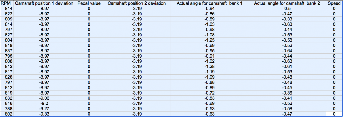
Car in question: 1999 C4, M96.02, 41k miles (had it since 20k miles), original/stock IMS bearing Alright, so I stumbled on some posts regarding durametric readouts for camshaft deviation to check into the health of the IMS. I remembered I logged a bunch of real-time parameters back in 2012 just to establish a baseline with my new Durametric tool at the time. I finally found my old hard drive with the data and to my surprise, my camshaft position 1 deviation read -8.97 cold at idle and varied down to -9.53 when driving around. Camshaft deviation, position 2 is solidly at -3.19 regardless of engine speed. On another post, I read that the durametric software may have had issues logging this parameter at the time. No CELs, no logged errors, been running fine for the last three years, and yes, I drive the snot out of it. When I cut the oil filter I find the random tiny shards brown plastic from the variocam guides. I have a magnetic drain plug and have only seen a light amount of the typical fine metal on it. The previous owner kept meticulous records of all work done at the dealer, and no major engine work was ever done other than oil changes. I found a post about a potentially bent sensor plate on the cam where the engine is correctly timed but the sensor is reading the parameter incorrectly?? My thought at the moment is to not drive the car, pop the green plugs and check timing as well as pulling the sump pan for inspection. I also plan to log the camshaft deviations this week with the newer version of the software and see what I get. Assuming I get the same numbers, I have some questions: 1. Since the position 1 is moving around a little bit between running and idle (~0.78 degrees), should I start having my heart attack now? 2. If the timing is off by this amount, is it a simple re-timing of bank 1 if all else looks OK? 3. Dumb question also is how much timing adjustment can be made since the sprocket appears to have large slots for adjustment? 4. Another dumb question is if bank 1 skipped a tooth, would I know it already? 5. Should I just open up the bank 1 valve cover to inspect/replace the variocam pads? (trying to do the least invasive first) 6. Anything else to check/do? Thanks for reading.

- 36 replies
-
- 1
-
-
- camshaft deviation
- ims
- (and 4 more)