Welcome to RennTech.org Community, Guest
There are many great features available to you once you register at RennTech.org
You are free to view posts here, but you must log in to reply to existing posts, or to start your own new topic. Like most online communities, there are costs involved to maintain a site like this - so we encourage our members to donate. All donations go to the costs operating and maintaining this site. We prefer that guests take part in our community and we offer a lot in return to those willing to join our corner of the Porsche world. This site is 99 percent member supported (less than 1 percent comes from advertising) - so please consider an annual donation to keep this site running.
Here are some of the features available - once you register at RennTech.org
- View Classified Ads
- DIY Tutorials
- Porsche TSB Listings (limited)
- VIN Decoder
- Special Offers
-
OBD II P-Codes - Paint Codes
- Registry
- Videos System
- View Reviews
- and get rid of this welcome message
It takes just a few minutes to register, and it's FREE
Contributing Members also get these additional benefits:
(you become a Contributing Member by donating money to the operation of this site)
- No ads - advertisements are removed
- Access the Contributors Only Forum
- Contributing Members Only Downloads
- Send attachments with PMs
- All image/file storage limits are substantially increased for all Contributing Members
- Option Codes Lookup
- VIN Option Lookups (limited)


Domiac
-
Posts
121 -
Joined
-
Last visited
Content Type
Profiles
Events
Forums
External Paint Colors
Downloads
Tutorials
Links Directory
Collections
Store
Everything posted by Domiac
-
 After installing new bearing, IMS has moved somewhat further away from the flywheel side, I assume this is actually how it should work. During the installation I started using my dead blow hammer easier so that the IMS secures to the other side and then later applied more force so that my new bearing started to go in and finally I could install the snap ring. Just wanting to make sure my two images (before and after) look normal. Thank you!
-
I moved my crank tiny bit past TDC #1 overlap (see the image), otherwise it was impossible to lock camshaft 1. Once I managed to lock my camshaft 1 without excess force, I gently tapped the crank counter-clockwise just a tiny bit so that I could lock my crank using the lock pin. Hopefully I did not do something stupid as one should never move crank counter-clockwise. However the travel was very small, perhaps 1 degrees. Then I locked camshaft 2 with my fabricated tool, used metal sheets to install it quite tight because the original width was not exactly like the original. Popped cam1 tensioner out (yes, there was a pop once it comes out) and then I removed the IMS tensioner (no pop), both look good but I'll post pictures of these later. After that I took the IMSB flange out, which was really easy to remove. Finally using the fabulous LN Engineering tools, I removed IMSB, it also came out quite easy. I had however a habit of spraying small amount of lubrication to IMSB for several days before I took these actions today. Every day I got darker stuff out from IMSB until finally I got only clean oil, could be that this has helped me to remove IMSB more easier. The good news is that IMS looks perfectly aligned, old bearing looks like new and there really was no particles or such on the IMS area. Borescoping revealed simply clean oil 360 degrees, top, bottom, left, right and inside the IMS. There was some tiny crud on the bearing but looked like really old oil and the amount was really small. IMS had plenty of oil inside which I vacuumed carefully with a clean pipe just in case, even though everything looked really clean. Thanks for JFP (once again!), xmac and especially Ahsai for debugging my logic :-)
-
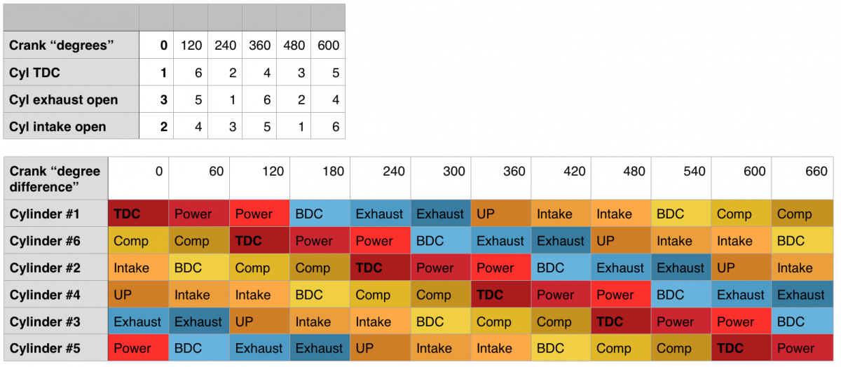
I believe that both of above are correct. I have only tried to install LN tool to bank 1 once, it might very well go easier to my cams if I rotate another 719 - 720 degrees, getting the lock installed requires some finesse on turning the crank. Yes, compression TDC #1 will have stress on bank 1 as then there are two valves open on bank 1. Overlap TDC #1 on the other hand means there are no valves open on bank 1. I took the liberty to quote porsche52 "Board Certified Porsche Trauma Surgeon / Cayenne Grief Counselor" from rennlist, hopefully this is OK, here's part of the instructions on how to time bank 2. "When you are just timing one bank, you must, I repeat MUST know for sure that the other bank (bank 1 in this case) is on TDC compression when you install the bank 2 cams in on overlap!! Cams are installed on OVERLAP (intake is just opening and exhaust is closing) For cyl#4 the camshaft lobes should point away from eachother when on overlap. (FYI, cams are installed on overlap because they are relaxed, no valves open, no pressure on cams for that bank), All you need to do is pull the cam plugs, (little green plugs, at the end of the cam cover) to see how the cams are allocated. When you pull out your green cam plugs, opposite end of camshaft sprockets. So for Bank 1 they will be on the front of the engine, below the alternator etc... for bank 2 they will be on the back of the engine (flywheel side). Once you have the plugs removed, you will see the ends of the camshafts. Rotate engine to TDC , the crank pully is marked "OT" and there will be a notch in the pully that lines up with a casting mark in the engine case the reads " OT Zyl 1". Fix the pully with pin, through hole marked "OT". You are now on either TDC compression #1 or overlap #1. This is why you must pull the green cam plugs. With the crank fixed @TDC, look at the ends of your camshafts for bank 1, If the smaller circular cutouts are pointing away from the engine then it can be said that cylinder #1 is on TDC overlap and cylinder #4 is on TDC compression. If the smaller circualr cutouts are pointing inward toward engine, then it can now be said that cyl #4 is on TDC overlap and cyl #1 is on TDC compression." After reading Ahsai's last post and porsche52 comments, I am quite confident that also on a 3-chain variocam engine, to perform IMS work, one must: 1) Crank clockwise until overlap TDC #1 is seen - cyl #1 exhaust has just closed, cyl #1 intake is just about to open - cyl #6 exhaust open, cyl #5 intake open - bank 1 smaller circular cutouts are pointing away from the engine (or when looking at bank 1 and intake camshaft is above and exhaust camshaft is below, then smaller circular cutouts are on the left side, larger cutouts on the right side) 2) Lock bank 1 Once again, this means compression TDC #4 and overlap TDC #1. I am glad we got this figured out, special thanks to Ahsai! I'll mark this message as a solution after few days, unless someone feels my logic is flawed. The image on this message shows the "360" column which we are looking for. PS. A small amendment for Ahsai's last message. On a variocam engine, intake is only max. 2mm open at any given time, exhaust goes always up to 10mm. One would need to activate variocam somehow manually if you wish to get 10mm opening for intakes. Then again, it would seem to be impossible to activate variocam "manually" in such way that you would get intake valve travel to 10mm as there is no oil pressure when the engine is not running.
-
Right now I am at 360 degrees (TDC #4 just about to ignite). I am sure that if I rotate another 360 degrees (getting to TDC #1 just about to ignite), I can fit LN Engineering camshaft locking tool again to bank 2 just fine. After this I'd be back on the situation where I am on my first message on this thread: - cyl #2 intake valves open - cyl #3 exhaust valves open => meaning cyl #6 would fire next, then #2, then #4, then #3 and then #5. I truly hope this endeavour produces meaningful data to others too :-)
-
1. Durametric: Camshaft position deviations: 1,53 and 2,58 - but this was a measurement taken while car was idling (not with high RPMs) and this measurement was taken just before http://www.renntech.org/forums/topic/45550-cylinder-misfire-gasket-blown-inside-bore/ . Still, I doubt my paper journey has nothing to do with the issue at hand :-) 2. I cannot put LN locking tool to either banks anymore after I rotated 360. It _might_ go in bank 1 but it would require substantial violence (bending) to get it in by hand. That being said, it could be that if I turn 720 and retry inserting LN locking tool to bank 1, I might get it in with lesser amount of force. Since my first message in this thread, I have already moved 360 and now I suspect I am on TDC #4 (definition option 1). I'll do another 719+ degrees tomorrow and see if I can fit LN tool finally to bank 1. This must be a topic that interests other 3-chain engine owners upgrading their IMS, hopefully we get a proper closure at some point. Thanks Ahsai!
-
Option 2 is perfectly consistent for my 3-chain 996 engine. I have inspected carefully how the pistons and valves move for multiple times now. I am wondering if option 1 is still valid and with 3-chain engines the bore hole circles are meant to be opposite when compared to a 5-chain engine. Then again, option 2 might be valid, I have failed to find information about this from all my sources. I am at loss here :huh: and unable to proceed with my IMS change as I wish to be sure I have my cams in correct position before proceeding. Please anyone, share your thoughts!
-
To be clear, my original table is still a fact, that is how my valves and cylinders act when I turn my crank clockwise. Only question here is how Porsche defines TDC for Zyl #1. Option 1) TDC for Zyl #1 means top dead centre for cylinder 1 which is about to ignite, if you move 0 - 120 degrees forward, still all valves are closed for cylinder 1. Same thing if one would move 0 - 120 degrees backwards (do not however do this), all valves are closed for cylinder 1. Option 2) TDC for Zyl #1 means top dead centre for cylinder 1 which is about to come into intake stroke, if you move 10-120 degrees forward, you'll see that intake valve is open See the attached image to this post, this table is assuming option 2 just like Ahsai explained on his message. Now, if anyone know which one of these is proper, please let me know. Thanks!
-
Yes, then my valve and piston behaviour would be perfectly consistent. Actually I have given this a thought, but why would Porsche define TDC @ 1 in such way that cylinder #1 it is just coming into intake stroke and intake valve is just about to open? I'd think that "Putting TDC for cylinder #1" means that you find the top dead centre for cylinder #1 just after compression stroke and before power stroke, meaning the ignition is just about to happen and all valves are close before and after TDC. Thanks a lot for the answer, I'd like to get some more people to support this theory.
-
Let's assume I was on TDC #4 during 0 degrees. That means that I should have seen the following: - intake #5 open - exhaust #6 open But that was not the case, instead I saw #2 intake and #3 exhaust open (my first message). This means that #2 is near bottom still just finishing power stroke, cylinder full of exhaust gasses. Why #2 intake would be open at this very moment (0 degrees) pushing gasses back into intake manifold when piston soon begins to go up? To compare, here's another table which assumes TDC #4 during 0 degrees, which I feel is wrong.
-
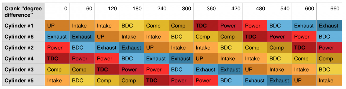
Gentlemen, I beg to disagree. I constructed a simple table that shows cylinder stages based on the firing order. See the attached image. Note, here I assume that TDC #1 is 0 degrees, in reality it might be something else but that is irrelevant. I find it impossible that I was TDC #4, just see the table and remember that my valves were at 0 degrees like this: - #2 intake valves open - #3 exhaust valves open Hence I must be TDC #1 because cylinder #6 is going TDC next, and then cylinder #2. I decided to turn crank some more and it supports my feeling that I was indeed TDC #1. At 0 degrees, results are the same what I stated on my first message - #2 intake valves open - #3 exhaust valves open - matches perfectly with my table's 0 column At 60 degrees, results are now: - #2 intake valves closed - #3 exhaust valves open - #4 intake valves starting to open - matches perfectly with my table's 60 column At 120 degrees, results are now: - #4 intake valves open - #5 exhaust valves open - matches perfectly with my table's 120 column At 360 degrees, results are now: - #6 exhaust valves open - #5 intake valves open - matches perfectly with my table's 360 column So, in my opinion the content on my first message is correct. But now I have turned 360 degrees clockwise, I have TDC for Cyl #4. LN Engineering camshaft lock tool does not fit either bank anymore. It might fit on bank 1 if I'd do 720 and carefully try to jam it in, it would be tight however that much I can see already. Any help on this would be highly welcome! :help:
-
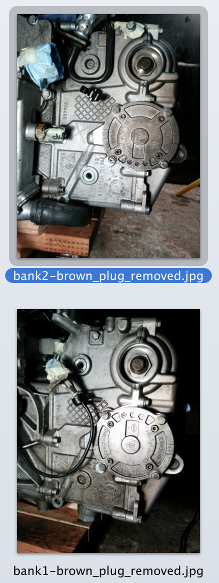
Pulling the big brown plugs on my banks did not provide anything useful. They simply reveal camshaft sprockets but without any such markings that could help figuring out TDC for cylinder #1.
-
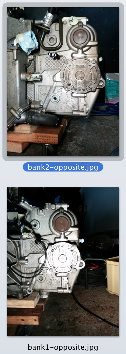
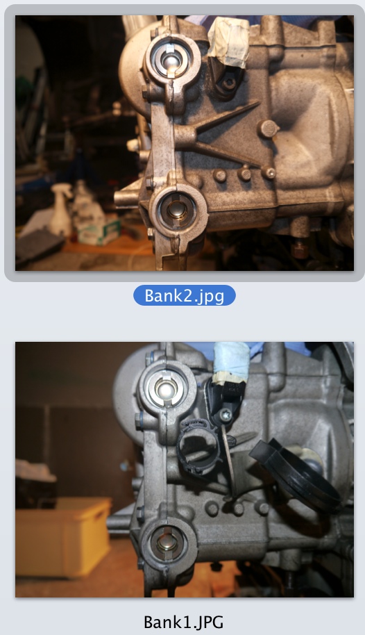
My 2004 3.6L 3-chain engine has only 2 green plugs on one side and 1 larger brown plug on the other side per each bank. This engine does not have the third opposite green plug per each bank as with 5-chain engines. My thinking is that if I remove the brown plugs, I should gain the opposite access to my intake camshaft. Now I wonder where should the notch point at on a 3-chain engine for TDC #1. Have to check my manuals, only problem is that my Bentley seems to be mostly for 5-chain (all images at least) and WSM is definitely missing 3-chain. Here's couple pics more of the opposite banks (dropbox has larger resolution), the look of 3-chain engines are quite different.
-
xmac, for clarity, I added two more pics to dropbox, a combined shot of the camshaft bore holes for bank1 and another one for bank2. Once again this is a 3-chain engine. Also, if anyone knows, I'd be really interested to undestand the following: If I am on TDC #4 right now, then it means that #2 is near bottom still just finishing power stroke, cylinder full of exhaust gasses. If so, then why #2 intake would be open at this very moment pushing gasses back into intake manifold when piston soon begins to go up? :notworthy:
-
Sorry, updated my previous message from "if I am on TDC #1 right now" into "if I am on TDC #4 right now", big difference..
-
I have pulled out all four cam plugs out. All four camshaft bore holes notches are vertical (up/down). My answer to you contained a dropbox link (https://www.dropbox.com/sh/vd9i43skh9nifl6/p_KlLwJcMX) that shows four images (bank 1 intake, bank 1 exhaust, bank 2 intake and bank 2 exhaust camshaft bore holes images). File names are visible bottom left on the dropbox UI. Notice that the shadow and close camera orientation makes the angle for bank 1 a bit weird (this is not exact science, but it might be a bit off still). The real question is that if I am on TDC #4 right now, then it means that #2 is near bottom still just finishing power stroke, cylinder full of exhaust gasses. If so, then why #2 intake would be open at this very moment pushing gasses back into intake manifold when piston soon begins to go up? I am beginning to wonder that is there another feasible way to verify this, DME needs to know this too :-) Thanks guys!
-
Only thing I cannot figure out is that if I have TDC for Cyl #4 then why my valves are like this: - Cyl #2 intake valves open - Cyl #3 exhaust valves open (- Cyl #4 exchaust valves open 1-2mm) Now, the firing order is 1, 6, 2, 4, 3, 5. And if I'm TDC for Cyl #4 then - #3 is going to TDC in 120 degrees but how could it as it is currently on exhaust? - #2 has gone past TDC 120 degrees ago approaching BDC but why does it have intake open? However, not sure how much intake/exhaust overlap. Have tried to find out specs from the web, not succeeded. Thinking of the firing order, TDC for Cyl #1 sounds logical. But, I am more than likely wrong and I'll do the 360 tomorrow.
-
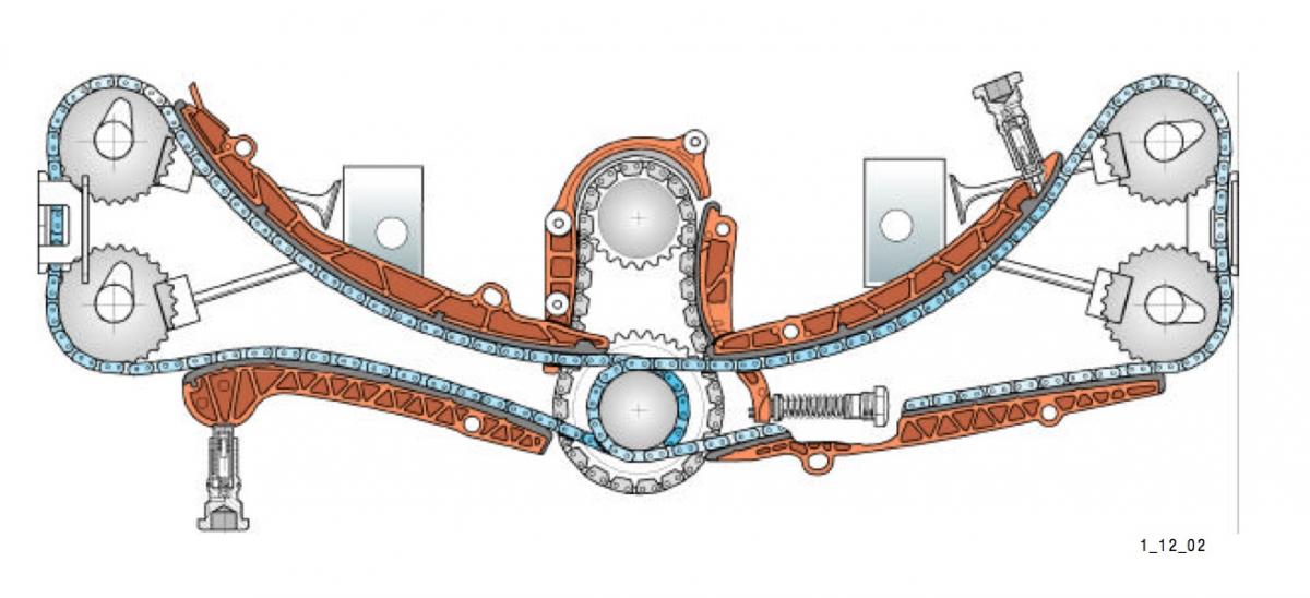
Actually it became clear to me once I inspected one of my workshop manuals, here's an image for everyone who are interested of. You can interpret this image just like you would look 996 from the back of the car, seeing serpentine right in front of you. Another better way is to say that on the image, bank 1 is on the left and bank 2 on the right.
-
Sorry, forgot to mention that my car is 996, 2004, 3.6L, 3-chain. The image on this post is done by me and it is from my engine. Yes, one should never use "driver's side" or "left bank" or such, that is quite ambiguous. Problem here is that LN does not use "bank" terminology at all. Read carefully what I wrote to my initial post using bold font, it says it all :-) I was quite certain that I got it right but your response validated that my assumptions were right. Background to this question is that I do like to double check things through this forum before taking action, especially when we are talking of IMS change. Thank you!
-
Gentlemen, I stand corrected. Will do 360 tomorrow and write a closure here. Yes, one should always turn crank clockwise only.
-
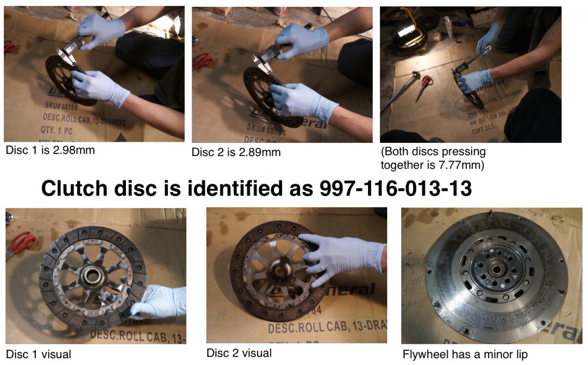
Car is 996 Carrera, 2004, 3.6L, 85t miles. Please have a look at the picture. I suspect that the clutch has been changed at least once on this car. Measurements for the discs are 2.98mm and 2.89mm. Marks on disc 1 are clearly visible, on disc 2 some of them are not perfect anymore. Would anyone happen to know what width the original discs have and what is the minimum width before change is required? It would be nice to know how long due is this clutch before I reinstall my tranny and engine back to my car. This clutch disc is identified as 997-116-013-13. Good quality images here: https://www.dropbox.com/sh/6v7k6w2trilayhd/yzH4BkI4BU Thank you!
-
Sure, there you go: https://www.dropbox.com/sh/vd9i43skh9nifl6/p_KlLwJcMX I am off 360, if I can trust that your engine works like mine (probably it does) when it comes to your image.
-
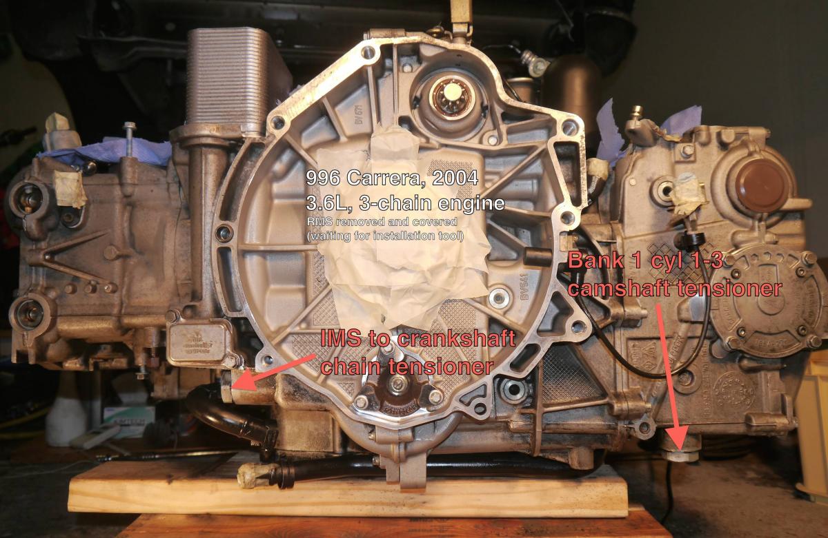
LN Engineering Retrofit Kit Instructions - Rev 18 Jan 14. state the following: Step 6. Lock camshaft in head with tensioner accessed from underside of the engine, closest to flywheel. Which head? Challenge is that there exists two tensioners that can (kind of) match to above description. When looking towards the flywheel, about 10 inches left from the IMS flange, under the engine, you will find a horizontally aligned tensioner. This should be the IMS chain tensioner and this one is closest to flywheel, however it is not located "in head". When looking towards the flywheel, about 15 inches right from the IMS flange, under the engine, you will find a vertically aligned tensioner. This should be the cylinder 1-3 camshaft chain tensioner and it is located beneath bank 1, second closest tensioner to flywheel. Now, which one of the banks should I lock? Look again at the instruction text and notice that both are close to flywheel and underside of the engine :-) Step 7. Remove the IMS to crankshaft chain tensioner as well as well the chain tensioner on the cylinder head for which you have locked the cam. Well, this depends on which bank I locked. My pick would be to lock bank 1. After all bank 1 chain is directly coupled with the flywheel side of the IMS. Then remove both tensioners visible on my image. My plan is to follow LN's instructions by the book and I do understand that I am solely responsible of the outcome. The only exception is that I'd like to lock all my cams (not only bank 1 but also bank 2), I can fabricate another cam lock tool, I assume this is safe thing to do. Would you agree? PS. Would be great if next revision would add wording "lock bank 1" instead of "lock camshaft in head with tensioner closest to flywheel"
-
Yes, I've seen this image. It is exactly the Xmac's thread that puts me in doubt that I am off by 360 degrees. Bank 1's exhaust camshaft bore hole looks just like the middle image, smaller circle on the right side. Turning 360 would obviously mirror my camshafts. However, Xmac's 1999 car has a bit different engine, e.g. it has 5-chains whereas my engine has 3-chains + variocam. Another variable is the camshaft locking tool itself as I am using LN Engineering's tool and not the original Porsche locking tools. Weekend is coming. I'll continue having some r&r with my car on Friday and start it by rotating 360 degrees and try out LN Engineer's camshaft lock to bank 1.
-
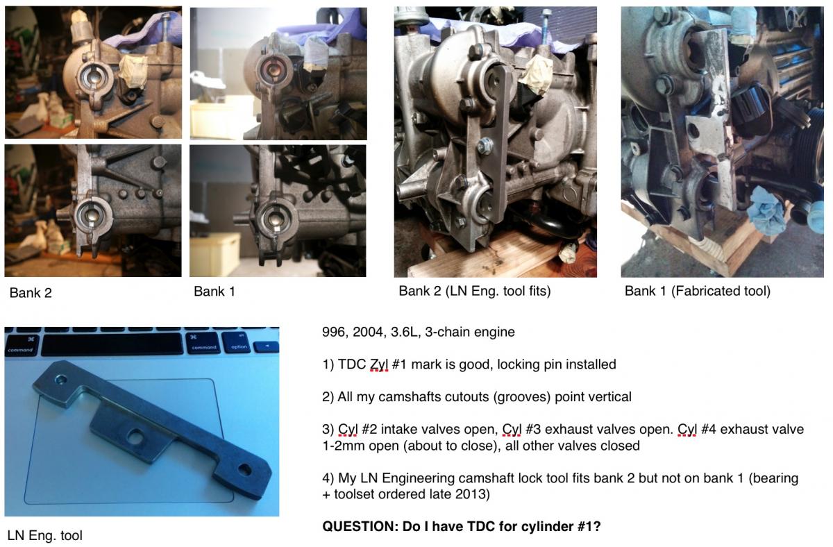
UPDATE: When you touch IMSB, do not set your engine like described on this message, see the full thread, especially the last messages. This message and the picture show compression TDC #1, meaning cylinder #1 top dead centre, just after compression and before power stroke. Instead you need to find out overlap TDC #1, meaning cylinder #1 top dead centre, just after exhaust and before intake stroke. If you cannot inspect valves e.g. using a borescope (or simply don't want to be overcautious), once you can lock bank 1 camshafts with the specified tool, you should have overlap TDC #1. ------------------------------------------------------------- Once again I turn to renntech to get some help on my wonderful 996 journey :king: See the pic and comment if I got TDC for #1 or not, thank you! Textual description follows below.. At my current crank position, the following are true 1) TDC Zyl #1 mark is good, locking pin installed 2) All my camshafts cutouts (grooves) point vertical 3) Cyl #2 intake valves open, Cyl #3 exhaust valves open. Cyl #4 exhaust valve 1-2mm open (about to close), all other valves closed 4) My LN Engineering camshaft lock tool fits bank 2 but not on bank 1 (bearing + toolset ordered late 2013) As the firing order is 1, 6, 2, 4, 3, 5 and thinking of my valve positions, I'd say I am on TDC for #1, would you agree? Turning crank another 360 degrees should get me to TDC for cyl #4, also the camshafts would turn 180 degrees and cutouts (grooves) align again as vertical. However, as the camshaft cutouts (grooves) are not symmetrical, I wish to double check that I have understood this correctly. I am not able to find clear pictures on how to lock camshafts for a 3-chain engine, therefore I am hesitant to proceed with my IMS work. Thanks again!
-
996 Oil filler tube replacment
Domiac replied to Eric's topic in 996 Series (Carrera, Carrera 4, Carrera 4S, Targa)
+1 for this. On my 10 year old 996 this was the only piece that broke amazingly easy while doing an engine & transmission drop. Changing this should be a no brainer as it is right in front of you once you open the lid. Just go to Pelican Parts, search for "996-106-226-52", click "more-info" and then "reviews", first comment supports Steve's and my comment. Or click http://www.pelicanparts.com/cgi-bin/ksearch/pel_search.cgi?SUPERCAT_FLAG=&make=&please_wait=N&forumid=&threadid=&command=DWsearch&description=996-106-226-52