Welcome to RennTech.org Community, Guest
There are many great features available to you once you register at RennTech.org
You are free to view posts here, but you must log in to reply to existing posts, or to start your own new topic. Like most online communities, there are costs involved to maintain a site like this - so we encourage our members to subscribe or donate. All subscriptions and donations go to the costs operating and maintaining this site. We prefer that guests take part in our community and we offer a lot in return to those willing to join our corner of the Porsche world. This site is 99 percent member supported (less than 1 percent comes from advertising) - so please consider an annual subscription or donation to keep this site running.
Here are some of the features available - once you subscribe RennTech.org
- View Classified Ads
- DIY Tutorials
- Porsche TSB Listings (limited)
- VIN Decoder
- Special Offers
- Paint Codes
- Registry
- Videos System
- View Reviews
- and get rid of this welcome message
It takes just a few minutes to register, and it's quality Porsche information at a low cost.
Contributing Members also get these additional benefits:
(you become a Contributing Member by subscribing or donating money to the operation of this site)
- No ads - advertisements are removed
- Access the Contributors Only Forum
- Contributing Members Only Downloads
- Send attachments with PMs
- All image/file storage limits are substantially increased for all Contributing Members
- Option Codes Lookup
- VIN Option Lookups (limited)


z281974
-
Posts
13 -
Joined
-
Last visited
z281974's Achievements
Member (1/1)
0
Reputation
-
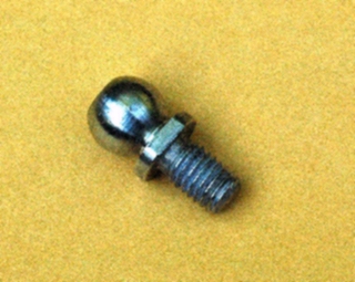
Found this part in rear drain
z281974 replied to z281974's topic in 986 Boxster Convertible Top Issues and Solutions
Thanks for the comments. I used a self-locking nut I found in my garage to secure the ball pin. I looked carefully around the area and saw no damage. I did stop using the top as soon as I noticed something awry. I checked the passenger side and noticed that the securing nut had a red mark on it aligned with a matching mark on the arm (to indicate loosening rotation, I believe). I never found the original nut. Tom -
I have an 01S and heard a popping sound while closing the top a few days ago. The top at closure was not as close to the windshield as usual. After going through the many posts here on this topic, I opened up the back and looked around, finding the driver's side ball pin in the drain hole. I then saw that the red clip on this side was not attached. I found a new nut for the ball pin and re-attached the ball pin and red clip. Everything seems to be back to normal - hopefully the red clip will stay attached to the ball?

-
Tom: Thanks for taking the time to explain this in detail. Doesn't sound too much like Greek anymore. If I now understand it correctly, as long as you use proper soldering technique, there will be no effect that the O2 sensors will be able to measure, so there is no problem using O2 sensors that must be soldered. Regards, Maurice. That's correct Maurice, there's nothing magical about soldering O2 sensor wiring. The main reason some universal replacement O2 sensor kits recommend crimping is because no special tools or skills are required. Regards, Tom
-
I soldered leads to connectors for a wideband O2 sensor, had some trouble but the engineer who designed it just now assured me the solder was not a problem, it did seem he was touchy about cutting the and splicing leads themselves though. I didn't ask for elaboration as it wasn't an issue in my case. People do solder thermocouple leads, bu it's recommended you use use silver and stager the connections. Regards, PK Thermocouples generate microvolts per degree C, and as such any extraneous voltage generated from dissimilar wire connections will adversely affect their accuracy. I've never seen thermocouple wires soldered in the 30+ years I've worked in defense and space industries. The O2 sensor produces approx. 700 millivolts nominal - many thousand times more voltage than the thermocouples' microvolts, so microvolt inaccuracies won't affect it. Also, the ECU is looking more for the large transitions in voltage of the O2 sensor (around the stoichiometric air/fuel ratio), rather than an absolute voltage value. Proper soldering technique involves first making a good physical contact between the 2 wires (wrapping the 2 wires together). The solder mostly seals and supports the connection and is not the primary electrical conduction path. Tom
-
Soldering is fine for the O2 wires. From an electrical standpoint there is no reason not to solder, as long as you're capable of performing the task. I've seen instructions from an universal O2 sensor indicating that soldering is ok. From my personal experience, I soldered the replacement O2 sensor in my Mercedes about 5 years ago without problem to date. Tom
-
He got the answer on the PPBB site. Your guess is only off by one ft-lb. Tightening torque: 25 Nm (19 ftlb)
-
Litronic is Porsche's name for the Xenon high intensity lighting. You should be able to buy the Porsche Litronic upgrade kit (containing both lights and upgrade wiring) for under $1500 from one of the discount Porsche dealers, such as Sunset or Suncoast. Tom
-
Putting O2 sensors into rear cats on MY03>
z281974 replied to atmorris's topic in 986 Series (Boxster, Boxster S)
I've never heard of stainless steel wire used for elctrical / electronic connections before. Automotive wire is usually either bare copper or pre-tinned copper (which may resemble stainless). But if the wire really is stainless, then you can't solder it. I based my soldering recommendation on my successful soldering of a Bosch O2 sensor on my Mercedes about 4 years ago, without subsequent CEL's. I can think of no reason why a properly soldered O2 connection would not work. I'm a retired engineer with 30+ years of the military / aerospace experience, so I'm not just talking off the top of my head. But on the other hand, a proper crimp will work too, and may require less expertise to implement. In any case, good luck with the project and keep us informed of your progress. Tom -
Putting O2 sensors into rear cats on MY03>
z281974 replied to atmorris's topic in 986 Series (Boxster, Boxster S)
Thanks. I just ordered them. Apparently they are all 18mm as I thought. I'm a little concerned about CELs too, but I figure I'm never gonna know until I try so...... Quite a few people have told me that they have lengthened their wiring harnesses on the O2 sensors without trouble. The key simple seems to be to do a good job when you do it, and don't solder the connections. Even Bosch's universal O2 sensor installation kit instructions refer to crimp connections. Glad you were able to quickly order them. I used one of them a few years ago on another car. As far as soldering goes, there's no electrical / electronic reason not to solder an O2 connection other than potential corrosion, where a good heat shrink cover has proven effective. Crimping is ok too, if you prefer that. Keep us informed on the project, as I'd like to duplicate your successful efforts on my 01S. Thanks. Tom T. -
Putting O2 sensors into rear cats on MY03>
z281974 replied to atmorris's topic in 986 Series (Boxster, Boxster S)
Andy, (1) You can pick up Oxygen Sensor fittings online at www.summitracing.com. The part number is SUM-2990 at $5.95 for the standard one, and SUM-2990S at $6.95 for the stainless one. (2) I would recommend locating the fitting on the pipe after the cat. You can look at some of the sport cat's that contain these fittings to gain an idea about location. (3) You can then cut and solder in some additional wire length to the Oxygen sensor leads as required, using heat shrink to seal. I believe that the longer leaded second O2 sensor assembly will fit the new configuration's closer location, and only one set of leads will need to be lengthened. I haven't done this yet, as I'm still concerned about possible CEL's, but I've heard of this approach working several times when using headers with sport cats. Using the original cats with an added O2 sensor should be equivalent. Good luck. Tom T. -
The CEL will not necessarily go off by itself immediately after a repair. I assume you didn't reset it? You must reset the CEL and give it some time. The two codes codes you mentioned indicate faults in both engine banks. While two oxygen sensors could have failed simultaneously, its not that likely. Good luck. Tom
-
Boxster speedometer: swapping to 996 unit
z281974 replied to smartrepair's topic in 986 Series (Boxster, Boxster S)
Here is a photo of an '02 996 Turbo cluster installed in an '01S Boxster. I added the 996 oil pressure sender and wired it up to the cluster. All gauges work including the 200 mph speedometer (which is just as accurate as the original 175 mph one), with the improved readout of the 02 OBC display. The only issue is that the oil level readings do not work due to the different functionality of the Turbo engine's oil reading - that is why the non-turbo gauge is preferred. I was originally just going to switch the two extra guages over to my Boxster cluster, but decided to stay with the new setup for the time being. Generaly, the Turbo gauges are cheaper on Fleabay because of this compatibility issue. -
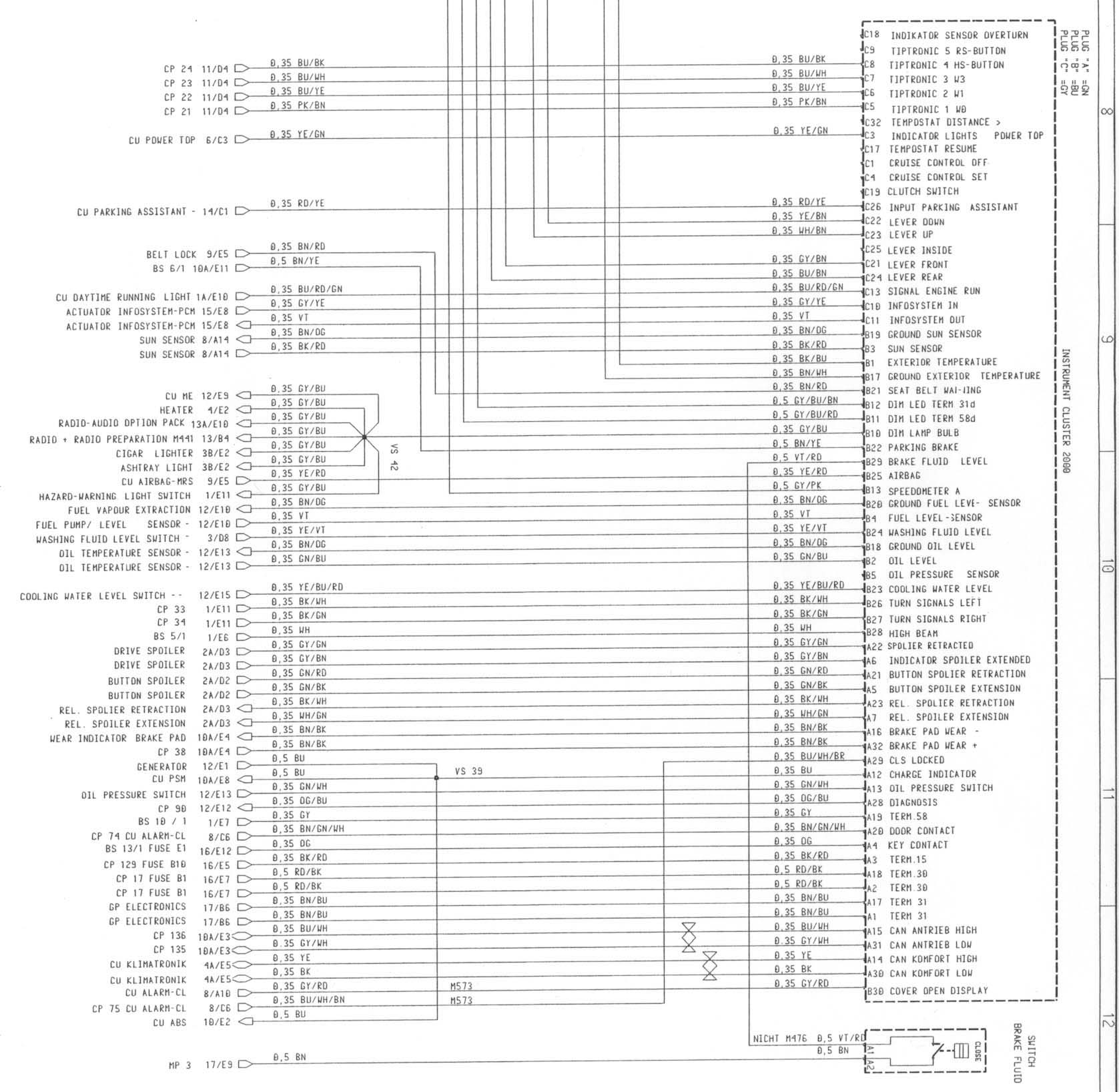
Instrument Cluster -Plug Wiring Diagram
z281974 replied to bluboy911's topic in 986 Series (Boxster, Boxster S)
Here's the instrument cluster wiring for a 2000 Boxster. The green is the "A" plug. I don't beleive there were many changes through 03. Anyway, it will get you started.