Welcome to RennTech.org Community, Guest
There are many great features available to you once you register at RennTech.org
You are free to view posts here, but you must log in to reply to existing posts, or to start your own new topic. Like most online communities, there are costs involved to maintain a site like this - so we encourage our members to subscribe or donate. All subscriptions and donations go to the costs operating and maintaining this site. We prefer that guests take part in our community and we offer a lot in return to those willing to join our corner of the Porsche world. This site is 99 percent member supported (less than 1 percent comes from advertising) - so please consider an annual subscription or donation to keep this site running.
Here are some of the features available - once you subscribe RennTech.org
- View Classified Ads
- DIY Tutorials
- Porsche TSB Listings (limited)
- VIN Decoder
- Special Offers
- Paint Codes
- Registry
- Videos System
- View Reviews
- and get rid of this welcome message
It takes just a few minutes to register, and it's quality Porsche information at a low cost.
Contributing Members also get these additional benefits:
(you become a Contributing Member by subscribing or donating money to the operation of this site)
- No ads - advertisements are removed
- Access the Contributors Only Forum
- Contributing Members Only Downloads
- Send attachments with PMs
- All image/file storage limits are substantially increased for all Contributing Members
- Option Codes Lookup
- VIN Option Lookups (limited)


KevinH90
-
Posts
254 -
Joined
-
Last visited
Content Type
Profiles
Events
Forums
External Paint Colors
Downloads
Tutorials
Links Directory
Collections
Classifieds
Store
Everything posted by KevinH90
-
Boxster S Instrument Panel Problem--LED Blew Up
KevinH90 replied to KentV's topic in 986 Series (Boxster, Boxster S)
What is the model year of your car? -
I didn't realize that you had a C4. The front-drive components must have required them to move the amp to the passenger side of the car. In most 996's and 986's it is right in the middle and mostly hidden by the spare tire. If you didn't have an amp, I think you would only be able to power two sets of speakers.
-
Look in the trunk and see if there is an amplifier slightly above and behind the spare tire. If you have the door speakers, it is likely that the car came with one of the audio packages that included the amp. I'm not an expert on amplifier technology, but it has electronics that split and filter the signal and send them to the appropriate speakers.
-
Windshield wipers do not park; no intermittent
KevinH90 replied to altbrewer's topic in 986 Series (Boxster, Boxster S)
Have you checked the wiper relay? It is in the kick panel in the driver foot well. I would first try removing and re-installing it. I don't like to just start swapping parts, but if that doesn't solve the problem I would buy a new relay and see if that works. This thread seems to cover a similar problem in a 996 and replacing the relay appears to have fixed it: http://www.renntech.org/forums/topic/11683-wipers-wont-stop-on-carrera-2/?hl=relay -
I have not disassembled a MK2 cluster, and there may be a difference with which I am unaware. I don't recall having to use excessive force at that stage.
-
It sounds like you were following the proper work procedure. If I recall correctly, I removed 2 torx screws. Then I pushed the two clips on the back towards the outside of the cluster. (This might seem a little scary at first as it feels as if they will break, but it disengages the electrical plugs that connect the two boards together. I may not have pushed them all the way apart on my first try.) Then I unclipped the large clip from the bottom of the cluster and it should fell easily into two halves. You can see some photos of disassembled gauge clusters here: http://986forum.com/forums/general-discussions/43017-carrera-gauge-swap.html and here: http://rennlist.com/forums/boxster-and-boxster-s-986-forum/915925-programming-a-996-cluster-to-work-in-a-986-a.html
-
wire damage in headlights
KevinH90 replied to longrowe's topic in 996 Series (Carrera, Carrera 4, Carrera 4S, Targa)
I ran into the same problem when I was refurbishing a set of litronic headlights. You can read about it here: http://986forum.com/forums/general-discussions/54697-advice-used-litronics.html I ended up opening up the headlight and replacing the wires. I was reluctant to do it, but it is not that difficult. There is a good discussion of how to do it in the thread including some pictures of replacement wiring. Randy's suggestion sounds like it would be less work. It appears that the problem is due to a German law that required the use of biodegradable wire insulation. There are references to Mercedes with the same problem. It may be better just to replace all the wire so that the problem does not return. Good luck. -
Retaining fastener for seat adjustment rod
KevinH90 replied to KevinH90's topic in 986 Series Part Number Requests
Thanks - I tried to find it myself in the on-line parts catalog,but my search technique needs some work. -
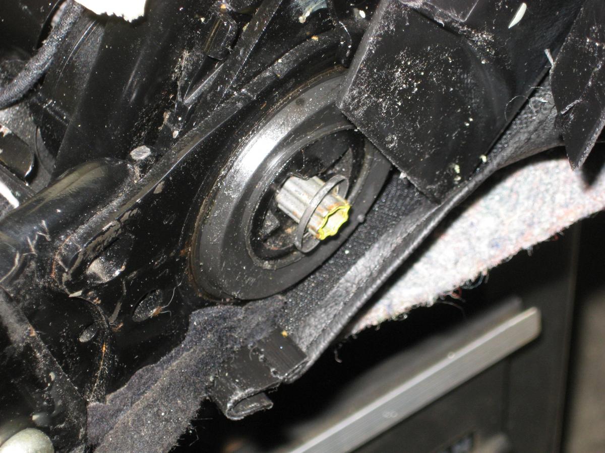
I have a 2000 Boxster 2.7 The part I need is shown in the attached picture. The picture shows the end of the rod that is rotated by the motor that controls the angle of the seat back .It is at the end of the rod that goes through the seat back and it locks the rod in place. It looks like a washer with several tabs on the inside. Thanks in advance for any assistance.

-
Upgrades for Boxster Seats I hope that others find this information helpful. Upgrading Two-Way Power Seats.pdf Author KevinH90 Category Boxster (986) - Mods Submitted 01/25/2016 09:05 AM Updated 03/05/2018 06:00 PM
-
I hope that others find this information helpful. Upgrading Two-Way Power Seats.pdf
-
With that amount of modification, it difficult to make any useful suggestions. I have limited experience with the CDR-23 and MOST system. I helped a co-worker replace a blown fuse on the back of his CDR-23 and it seemed that there was a fiber optic cable on the back that replaced several of the wires on my CDR-220. Is it possible that the previous owner totally removed the fiber optic cable and replaced it with copper wire?
-
It sounds like someone did some major butchery on your car, so you may have to run down several possible causes. The first one that comes to mind is that the amp in not turning on. I would start by checking the fuse box and see if the amp fuse is there or is blown. There should be a piece of paper in the fuse box cover and that will tell you which fuse is for the amp. Then check to see if the amp wiring is intact. There will be one wire that is the amp turn on wire and it could be damaged or disconnected. Unfortunately, I'm not as familiar with the 996 model year changes as I am with the 986. Is your head unit a CDR 23 or a CDR 220?
-
Look at the 4th post in this thread: http://986forum.com/forums/diy-project-guides/59936-diy-double-din-pioneer-sph-da120-installation.html It shows a similar connector in the back of a CDR 23 head unit.
-
I received some good technical information on integrating the mirror function. Unfortunately, it is not good news for my project. Here's a summary of the parts needed and the work required: 1. Replace the mirrors with ones equipped with the memory function. Standard electric mirrors are no good. You can tell by the number of pins on the connector. The memory function (and heating) requires 10 pins has. The standard electric mirror has 5 pins. 2. Install pins on the connector, get memory mirror pigtails from a breakers yard or even a whole new door loom. The big connector at the door that separates the door loom from the main loom doesn't have the pins needed either, so adding pins to that connector is needed, or you have to run the wires as one piece down to the driver seat to the control module. 3. Make the connections for the mirrors in the control module under the seat. The connections are very simple once you have the wiring from the mirrors in place. There are 9 wires to run to the drivers side and 5 to the passenger. On the driver side you need +5v, system ground, left/right, up/down to go to the mirror. there is also left/right drivers, up/down drivers, left/right pass and up/down pass to go the the mirror control switch. There is also a common motor connection that runs to both the mirror and the switch. On the passenger side you need +5v, system ground, left/right, up/down and the common motor connection. It may be possible to eliminate the common motor connection on the passenger side, as it is likely already there. If you want the passenger mirror to tilt when in reverse, you will also need to run a line from the 24 pin connector to the reverse lamp signal line. At a minimum, I'll need to wait until a set of reasonably priced memory mirrors become available. If I can install the memory components in the mirrors that are already on my car, I won't need to find a set that are the same color as my car or have them painted. I also noticed that the seat back tilt function did not respond to input from the memory module. Because I had reused the seat cushions and seat back from my two-way power seat, this would not be an issue for someone who swapped in an entire seat. It turns out that the driver's side memory seat has a different motor in the seat back. It has 4 connections. The part number for the seat back motor that is compatible with the memory module is 404.335 The motor for the two-way power seat and the passenger side seat is 404.334 and it has a two-wire connector. I was able to source a motor with memory for a good price, and I will finish the seat memory part of the project when I receive it. The future of the mirror memory is dependent on the availability of reasonably priced parts and I may decide it is not a high priority.
-
Aftermarket Nav/head unit question - 986 owners
KevinH90 replied to atmorris's topic in 986 Series (Boxster, Boxster S)
http://www.renntech.org/forums/tutorials/article/106-2003-2004-boxster-avic-d3-install-with-most-bus/ -
I've done some more research on this with the goal of understanding the mirror wiring. Here's the connector that attaches the wiring harness to my current non-memory mirrors: Note that there are quite a few empty sockets in the connector. Here's a picture of one of the wires from the harness that I have: Note that at the end of the wires there are two male terminals that appear like they will fit inside the connector of the mirror control. I think that the way this works is that there are two possible sources for the control signal of each mirror. One is from the switch near the driver's-side window and the other is from the memory control under the seat. So, when you control the mirror manually the signal comes from the control on the drivers door. When the memory unit takes over, it comes from the control box under the seat. Unfortunately, I do not have one complete intact harness. So, I'm going to have to scrounge for some parts before I can check my assumptions. Also, I found out that Porsche changed the configuration of the memory control in the 2001 model year. According to my Bentley Manual (page 02-25) when Porsche added the electronic front and rear lid releases they also added the individual key programming feature. So, I don't think that feature is available in my 2000. It may be better for me to use the wiring diagram from the 1998 vehicle than for the 2002 vehicle.
-
It is installed and working. It turns out that the red wire with the black stripe (Pin A1 on the 3-wire black connector) is the power for the button illumination on the memory control. That explains why the system worked when I used both 5V and 12V power to that wire. I will need to connect it to Bridge Plug BS7. I originally connected it 12V power under the seat, but that was constantly on. I will be coming back to this project in a few months. During my part acquisition process, I obtained these metal-plated control levers: I think they may be from a 996. I'm considering having them re-plated as I think that will look better than the silver-painted handles I'm currently using. So at a minimum I will be doing a cosmetic update and addressing the illumination issue. If I can find more information about the mirror function, I'll address that at the same time.
-
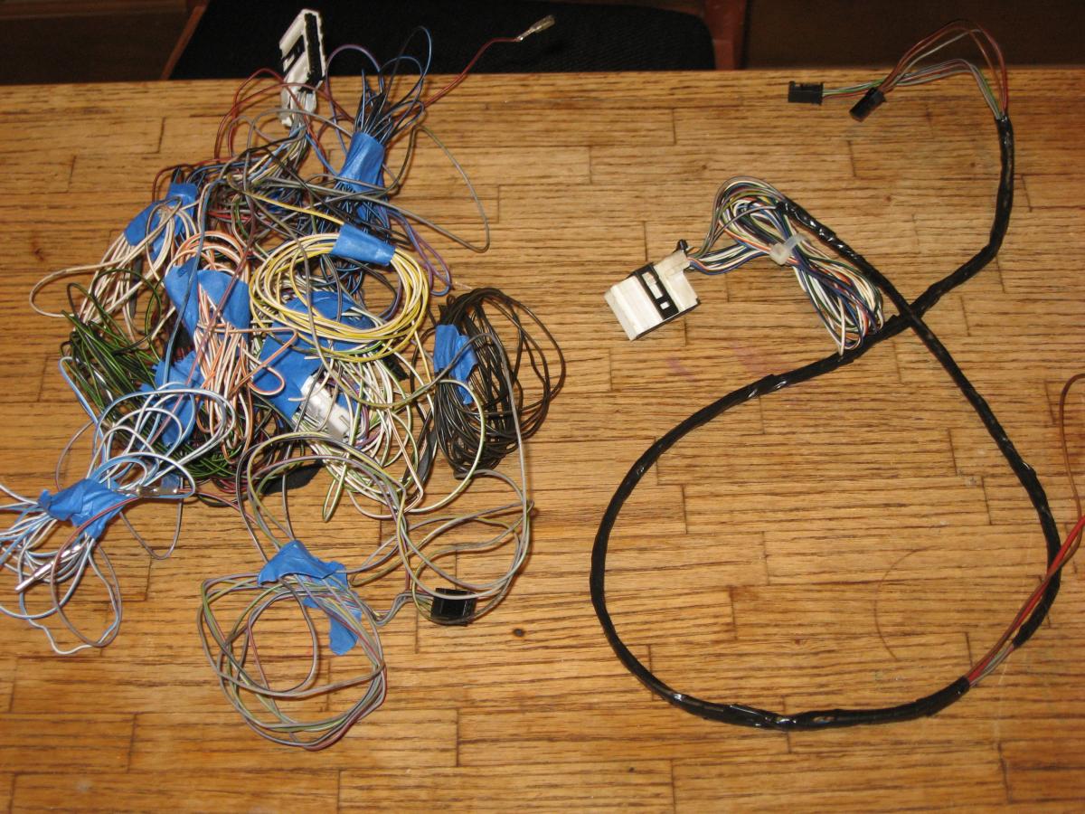
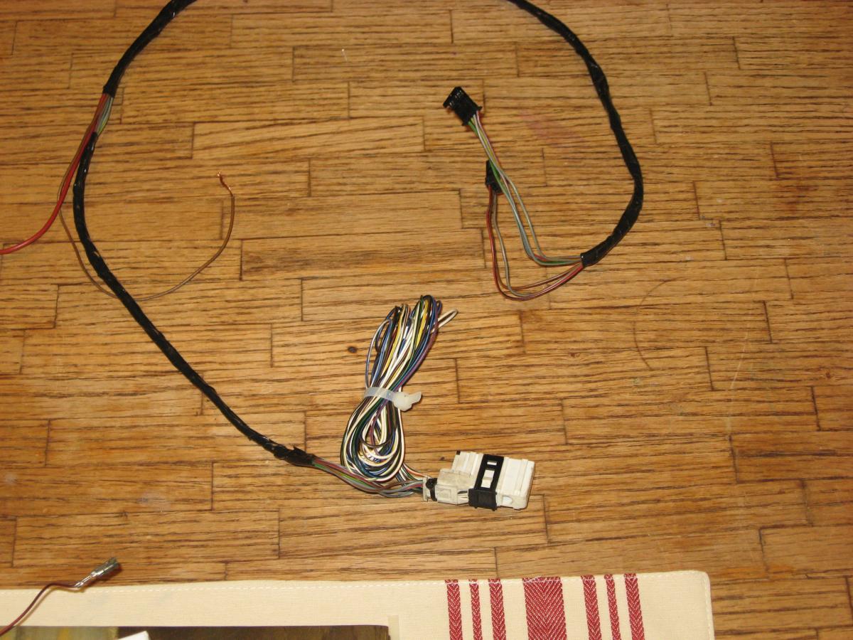
I will be back at work on Monday, so I'm planning to finish what I can pending more research on the mirror function. As luck would have it, I have parts from two different harnesses. Both have the connectors for the control unit in the door sill and the big white connector that attaches under the seat. As you can see, the one on the left in this picture is more complete, but it appears to be missing some connectors and terminals required for the mirrors and other interfaces. I'm planning to save that until I determine whether I can install the mirror function. The one on the right was cut out in two parts. I pieced it back together and made the second more limited harness. I've tested it on the bench (using 12 volt power as Richard suggested) and it works fine. I'm planning to install it tomorrow. I won't have 100 percent of the memory function, but it will be months before I have more time to dedicate to this project, so I may as well enjoy some of the fruits of my labor. Thanks for the help and if you have any other insights, please share them.
-
It has been a while since I did my project. I think I may have wet sanded when I was using the very fine grits. As Rockhouse suggests, try to obtain the Sylvania solvent before you become too aggressive with the sanding.
-
I used a quarter-sheet finishing sander and started with 320 grit. I progressed through 600, 1000 and 2000. Then I used a 3000 grit finishing disk in the 3M kit and then polished with the 3M compound. Some of the feedback I received was that 320 may have been unnecessary and that 400 grit would have been a good place to start.
-
I think you will be OK. It appears that your problem may be that you haven't totally removed the existing UV outer coating. I used a combination of the Sylvania and 3M kits when I restored my headlights. The advantages of the Sylvania kit are that it includes a solution that removes the existing UV layer which makes the headlight easier to sand and it has a protective coating that you put on at the end that smooths the surface and makes it shine. I liked the 3M kit because it had the drill attachment. Here's the thread in which I discussed my process: http://986forum.com/forums/general-discussions/54697-advice-used-litronics.html
-
Thanks Richard. I saw your post on Boxa.net too. I haven't had an opportunity to check out the wiring diagram, but I will before I install any components. The reason I tried the 5V power first was that pin A5 is labeled 5V and I thought the entire unit might be 5V. When I saw that it worked on 5V I decided not to try 12V and risk damage to the circuit board. What you say makes sense regarding the input from the key. However, to implement that feature I think I would need to have someone with a PIWIS or PST2 program the control box. Right now, I am planning to install the system with just the seat operating and wait until I have better information about the mirror function before I tackle that part of the project.
-
I made some progress today. I'm using an old computer power supply to test some ideas. The supply provides 12 volt, 5 volt and 3 volt power. The seat mechanism is hooked up to 12 volt and the memory function to 5 volt. I attached the red/black wire from the 3-wire plug to the 5 volt source and the brown wire to ground. As you can see in this Youtube video: https://youtu.be/LFAfb2JiGi4 the system is able to store and recall settings. (I unplugged the power source, and when I plugged it in again, the system was able to recall the settings.) Rather than run a wire to the relay carrier to obtain 5 volt power, I'm considering the purchase of a device like this http://www.amazon.com/KEEDOX%C2%AE-Converter-Power-Supply-Module/dp/B00A71CMDU/ref=sr_1_1?s=electronics&ie=UTF8&qid=1451585169&sr=1-1&keywords=12+volt+to+5+volt+converter This will convert the 12 volt power already at the seat to 5 volt power. I still need to decide whether adding the mirror control is feasible, so any thoughts on that part of the job are welcome.
-
I installed a new ignition switch on my Boxster at the beginning of the month and had issues within a couple of weeks. See this post: http://www.renntech.org/forums/topic/49343-light-switch-constant-illumination/ It turned out that the new ignition switch was defective. I see that there are other possible causes, based on the other responses. But, as I learned, you cannot rule out premature failure of a new part.