Welcome to RennTech.org Community, Guest
There are many great features available to you once you register at RennTech.org
You are free to view posts here, but you must log in to reply to existing posts, or to start your own new topic. Like most online communities, there are costs involved to maintain a site like this - so we encourage our members to subscribe or donate. All subscriptions and donations go to the costs operating and maintaining this site. We prefer that guests take part in our community and we offer a lot in return to those willing to join our corner of the Porsche world. This site is 99 percent member supported (less than 1 percent comes from advertising) - so please consider an annual subscription or donation to keep this site running.
Here are some of the features available - once you subscribe RennTech.org
- View Classified Ads
- DIY Tutorials
- Porsche TSB Listings (limited)
- VIN Decoder
- Special Offers
- Paint Codes
- Registry
- Videos System
- View Reviews
- and get rid of this welcome message
It takes just a few minutes to register, and it's quality Porsche information at a low cost.
Contributing Members also get these additional benefits:
(you become a Contributing Member by subscribing or donating money to the operation of this site)
- No ads - advertisements are removed
- Access the Contributors Only Forum
- Contributing Members Only Downloads
- Send attachments with PMs
- All image/file storage limits are substantially increased for all Contributing Members
- Option Codes Lookup
- VIN Option Lookups (limited)


zodman
-
Posts
120 -
Joined
-
Last visited
Content Type
Profiles
Events
Forums
Exterior Paint Colors
Downloads
Tutorials
Links Directory
Collections
Classifieds
Store
Everything posted by zodman
-
chain tensioner removal or loosening (for IMS)
zodman replied to zodman's topic in 986 Series (Boxster, Boxster S)
Got two quick questions on the LN Bearing. Specifically the small rubber seal on the shaft. Documentation doesn't mention if it should be on or off the bearing shaft when the bearing is sent to the deep freeze. Second one...Documentation also doesn't state whether that same small seal should be resting against the back wall of the shaft, behind the flange and nut. OR Should it be between the flange and the nut? Not that I'm one of those that needs the "Caution: Coffee Hot" signs on my morning cup, but this detail of where the rubber seal is supposed to be is a mystery... -
chain tensioner removal or loosening (for IMS)
zodman replied to zodman's topic in 986 Series (Boxster, Boxster S)
They'll provide a SSF retail partner for a private individual. I should have looked into it further, but I ended up buying from Sunset and Pelican the majority of what I needed. -
chain tensioner removal or loosening (for IMS)
zodman replied to zodman's topic in 986 Series (Boxster, Boxster S)
My understanding was that they are wholesale only...If they'll sell to anyone, I would have purchased as much as I could have from them to begin with. https://www.ssfautoparts.com/#page_signup -
chain tensioner removal or loosening (for IMS)
zodman replied to zodman's topic in 986 Series (Boxster, Boxster S)
Grainger will have the 290 and the 268 local to me within 7 miles on Monday. The closest local Stealer (just down the street from Grainger) only sells the t-fluid in 20 liter containers....I didn't bother to ask the price. Sunset will ship 3 liters to me for 26.80 a liter + shipping. If I had an "in" to SSF, that'd be great. Hate to see stuff come from there and sometimes travel up to 100 miles when I live only a few minutes away from there. -
chain tensioner removal or loosening (for IMS)
zodman replied to zodman's topic in 986 Series (Boxster, Boxster S)
Crazy World... I live less than 5 minutes from SSF Auto(the big wholesaler for a lot of P-parts), and anything I buy through Pelican that is shipped via FedEx has to travel well over a hundred miles to get to me, though I could drive over there and pick it up...burning less than a gallon of fuel and a half hour of my time(If I was allowed)....And there isn't a smudge of 268 or 290 within 30 miles of me. I've got a Grainger within 7 miles of me, and they don't have either in stock at their local store. -
chain tensioner removal or loosening (for IMS)
zodman replied to zodman's topic in 986 Series (Boxster, Boxster S)
Finding local sources here in the Bay Area for Loctite (that isn't super glue) is elusive to say the least, so I may have to find alternatives, but I'll seek out the Loctite# first. As for the 574, I've got Curil-T. I also have the Loctite 5900. If anyone here is in the BAY AREA knows where Loctite (in those numbers mentioned) is sold in stores, please either pm me or respond to this...Thanks. I'll shave off another 2mm on my tool and install clean and dry, I thought I read the new seal must be placed 3mm past the location of the former seal, therefore it would mate on untouched metal...I also take it you don't care for the use of Curil-T on the outside lip of the seal that kisses the crankcase... I'll pick up 3 liters of T-Fluid at a local Stealer. -
chain tensioner removal or loosening (for IMS)
zodman replied to zodman's topic in 986 Series (Boxster, Boxster S)
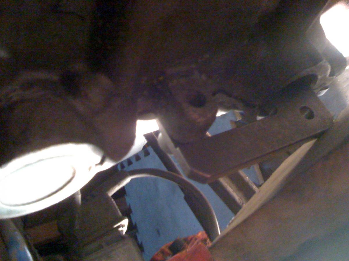
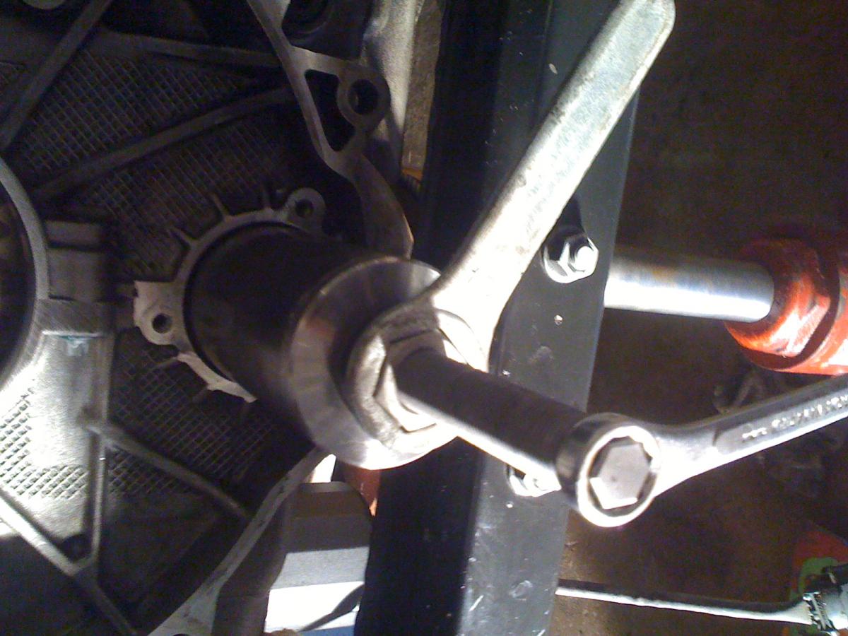
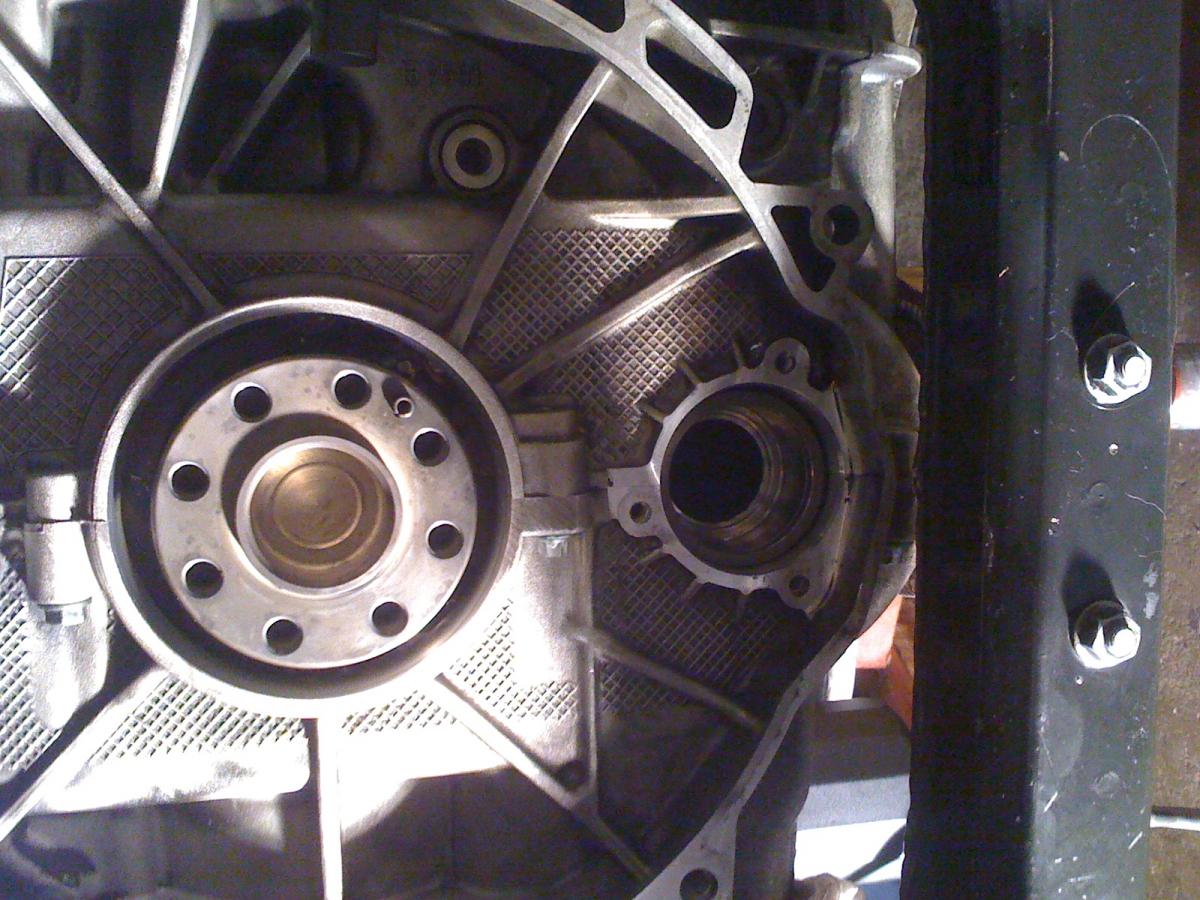
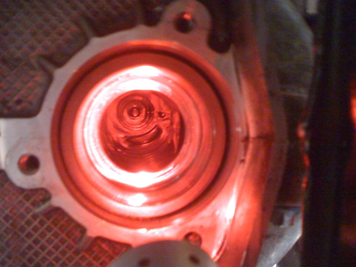
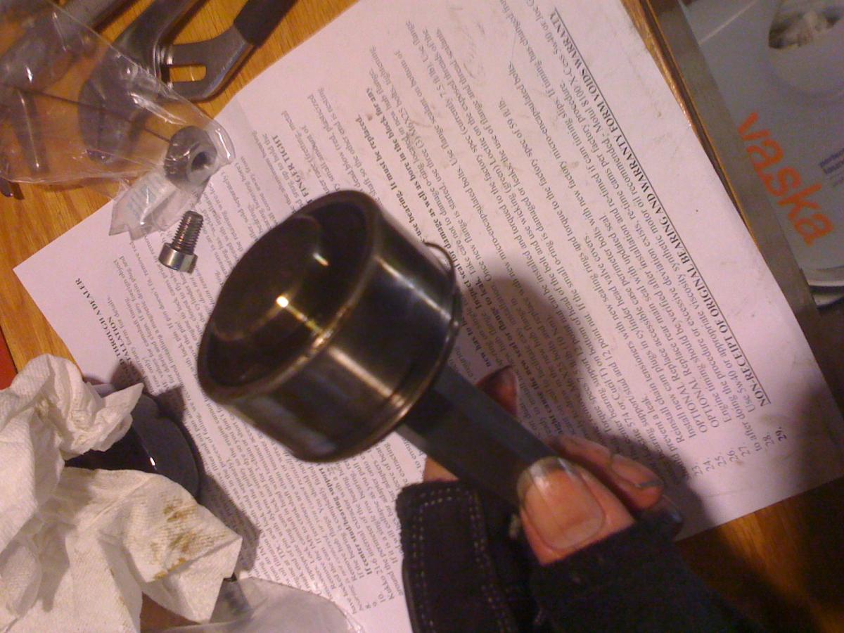
Got it locked down after rotating crank a few times, placed a wedge of wood between the bottom of the Cam lock and the chassis cross-brace. Checked position using dental mirror during each "jolt" to the engine when loosening the tensioners. Nostalgia shot...That 24mm tool on the big nut is from the first motorcycle I ever owned when I turned 24. It was a used Honda...But that's all I can remember...It was the tail end of the 80s after all. Bearing is off, had a little oil spill out from the tube. Using red light to eliminate glare. I see the shaft is pulled slightly to the upper left. May have to loosen tensioner behind driver seat after all. Am going to think about it. Here is the bearing by it's lonesome. At the edge, a touch of grime. Other than the loose screw in the picture, the bearing appears for all intents and purposes perfectly normal for 90k (or so) What flavor/weight of transmission fluid would you go with for these older boxsters? (Though it appears you favor the oem) Would loctite 242 be ok to use on the flywheel bolts? For the RMS, (being installed at a depth of 15mm - The previous one was at 12mm) would you pack the back of the seal with any lithium/moly wheel bearing grease...seems overkill, but someone did suggest that. And on the subject, would you pre oil the crankshaft with fresh engine oil or Olista Optimoly 3EP to help guide the new RMS seal on? I may have to mail you one of my prints when this is all done.
-
chain tensioner removal or loosening (for IMS)
zodman replied to zodman's topic in 986 Series (Boxster, Boxster S)
Thanks, on #1 I was certain it had to be there on 4-6 as that's why I wouldn't progress further. As for item #3 just want to reassure you that was just for photo clarity, and to see what it should look like if it is set proper. I wouldn't move it off TDC during the procedure, or not have the locking pin in place. I'll give the crank a few clockwise rotations to see if it's old bones loosen up....usually works for me in the morning. -
chain tensioner removal or loosening (for IMS)
zodman replied to zodman's topic in 986 Series (Boxster, Boxster S)
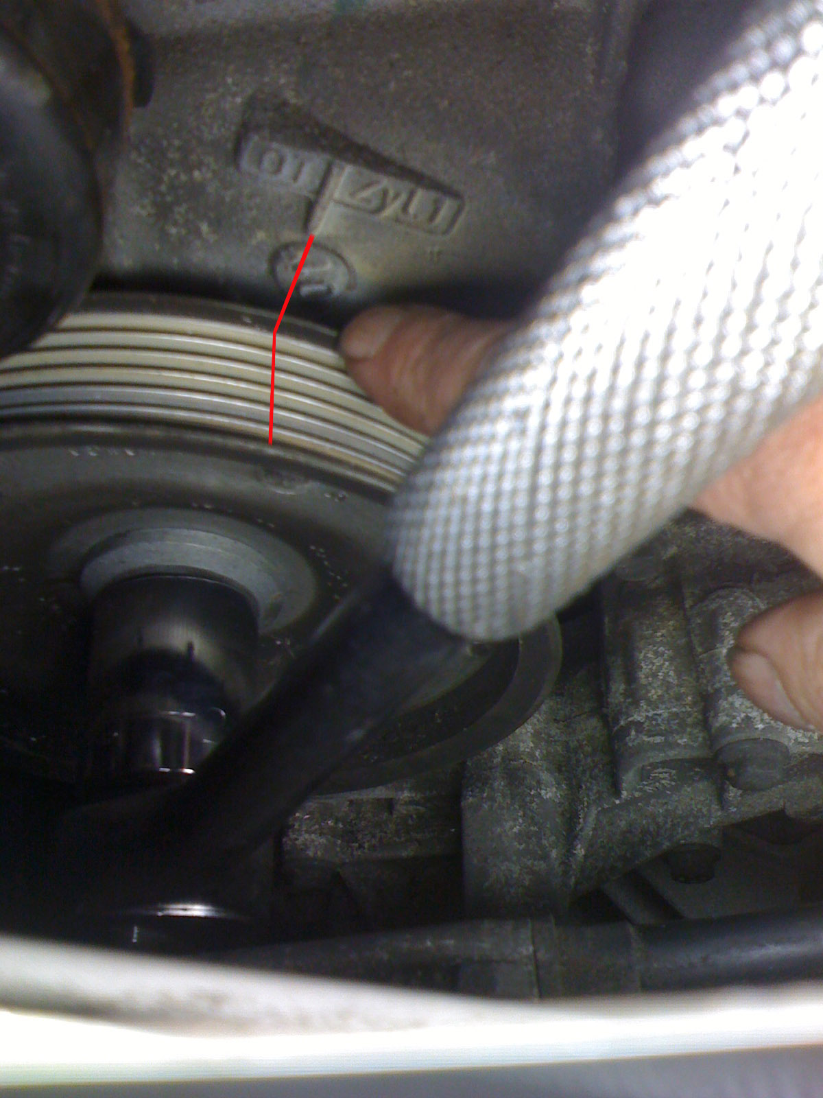
Ok, I can verify that the engine is at TDC for cyl 1 because the intake cam plug (by the AOS) has the notch pointing right(eastward). When I try to install the five-chain cam lock on the 4-6 cyl. exhaust cams, it does not fit square in the two notches. It will nest in the top, but it is cleaving a little too much towards the flywheel side, leaving a slight gap towards the left. Fudging it a tad to fit in proper isn't happening. Since it isn't lining up properly, I'm hesitant about proceeding further with cyls 4-6 because I want a nice snug fit and I suspect it may pop out once I start to loosen the tensioners. If I step out of TDC for a moment, as in the attached picture, I can get it to mate into the 4-6 exhaust cam....In the photo, the edge of my dirty fingernail is touching the notch on the crank. The redline is an eyeball guess of the true TDC. - I'm just demonstrating the distance from the crankshaft perspective since I can't get any decent photos on the other side because of space restrictions...So it's off somewhere in the distance from the redline to my finger for 4-6. However, when I take that same 5 chain lock and put it on the Cyls 1-3(passenger side by passenger seat and going forward to the TDC) the locking point it is a perfect fit in cly 1-3....Snug as a bug as long as I don't cinch it up. On the Cyl 1-3 side, the problem is in the tool, once it is carefully *cinched up, the raised edge of the tool hits the side of the engine. If it was machined down about 2mm further, it would kiss the side of the engine. As it stands, either the tool has to be shaved a touch or the little nib that sticks out for cam locks on the head needs to be shaved. It fits square there on Cyl 4-6, but as I mentioned, I'm not confident it will stay put once the tensioners are removed. Do I have a slight timing issue with 4-6 that should be addressed first? Or is the ever so slight deviation a norm for these older cars? If I can just put the lock on the Cyl 1-3 and proceed with the ims install, (maybe using a washer to even up the *mating) instead of cyls 4-6 that should work ok right? I was initially thinking I could eye the lock on 4-6 while I was relieving the tension, but it may not happen that way after all. Thanks again for your time and your input.
-
chain tensioner removal or loosening (for IMS)
zodman replied to zodman's topic in 986 Series (Boxster, Boxster S)
As someone that does this for a living, let me give you some basics: Forget about anyone's instructions except for LN Engineering. While some people have gotten away using the so-called set screw method, others have had major league problems. Because the gear you are pushing on with the set screws is a press fit to the IMS shaft, you can actually move the gear on the shaft, which then requires taking the engine apart to fix. Bad idea. Get a copy of the LN instructions and follow them to the letter, they are the only ones known to not create problems; and don't cheap out on getting the necessary tooling. TDC is only for the #1 cylinder, there is no other engine position will minimize valve spring loading, which is what will try to rotate the engine during this process. Once the engine is rotated to TDC (turning clockwise only), it should not be moved and the locking pin should not be removed until everything is reassembled. The "green stuff" on the bolts is a micro encapsulation Porsche uses to help hold the bolts tight. The blue on the flywheel bolts is thread locker. And while on the subject, you should not even consider reusing any of the pressure plate or flywheel bolts, they are single use fasteners. The three chain tensioners can be removed. It is always a good idea to clean them and at least check them for signs of wear as it is a pain in the butt to go back in to replace a weak one. Be sure to note which tensioner came from where, they are not all the same. A blown AOS will leave a lot of oil in the intake system, and take forever to burn off unless you take the system apart and manually clean everything out. Buy a leak down tester rather than a compression gauge, leak down tests tell you a lot more than a simple compression test. Thanks JFP in PA, as always, you give wizened informative clarity. I wouldn't even think of reusing the flywheel bolts or pressure plate bolts (or old seals), and I did purchase the LN toolkit. But in reading instruction #6, from LN's site(Rev16 Jan 2013), it is not specifically stating "which" exhaust camshaft to place the 5 chain lock on. According to the Bentley YouTube video, at least on the three chain motors, both cyl 1-3 and 4-6 intake and exhaust camshafts were locked into place and all three tensioners removed. LN's site under #7 suggests loosening/removing the third one only if "centeredness" isn't achieved. Also, if the tensioners are removed, (at least the two) don't they have to be submerged in new oil prior to being reinstalled? If memory serves, I saw that on a rebuild. I'll be sure to follow the visual cues on the tensioner and the engine for which is which. ---- From LN: #6: Use appropriate long cam lock tool for 3-chain or short cam lock tool for 5-chain engine to lock cams prior to removing chain tensioners. Lock camshaft in head with tensioner accessed from underside of the engine, closest to flywheel. #7. Remove the IMS to crankshaft chain tensioner as well as well the chain tensioner on the cylinder head for which you have locked the cam. If tensioners are worn or were noisy at startup, replace. NOTE: If the flange does not come off easily, the bearing is not centered, or you cannot reinstall the flange, then loosen and/or remove the third chain tensioner. ---- That second sentence in #6 is hard to *interpret/visualize. If I read #6 & #7 correctly, Only two tensioners need to be removed (Ims/crankshaft & the tensioner for 4-6 cyl.), the third optional (cyl 1-3 - by the AC behind the driver seat) if necessity applies. The cams on the left side of the flywheel (If you are facing the flywheel) are cylinders 4-6, the upper is the intake the lower is the exhaust. On a 5 chain motor, put the 5-chain lock on the exhaust cam for cyl. 4-6. Is that correct? {*Addendum: In some prior posts I had originally mixed up referring which engine sides were which before because of my dyslexia - calling the drivers side cylinders 1-3 and passenger side 4-6. Sorry if that adds to any confusion. That's why visuals usually clear up things for me, but I don't usually have problems interpreting what I've read if I read something several times.} On the AOS, that was changed out about 20K ago...maybe a bit less. It was the older problematic aos that was replaced. Though I could cut the 3 chain lock to work as a second 5-chain, the thickness is different. The 5 - chain lock is slightly beveled. Though I could "bevel" the altered 3 chain in addition to cutting it, would it "fit" on a five chain as it is, keeping the integrity of the timing (and the tool)intact? Thanks again for your help with this...I'll be making a donation to the site soon. -
Hi all and happy festivus, I can't find any literature on the LN special tools if the width differences on the 5 chain and 3 chain camshaft locks means that you needn't bother putting the 3 chain lock on Cyls 1-3 (or on a 5-chain motor) if you've already got the 5 chain lock on Cyls 4-6...just for the extra piece of mind that locking both sides would offer. I see the 3-chain lock is slightly thicker, and doesn't seem to fit in. And as for rotating the engine at TDC, is it TDC for cyl 4-6 or TDC for 1-3? Also, since I've got the 5-chain version with the double row bearing, do all the chain tensioners need to be loosened/removed? LN documents just the IMS and cyl 4-6(closest to flywheel) removal. I seem to recall that with the 5 chains, two of the tensioners could be loosened to their last thread and don't have to be removed, the one in the back, behind the drivers seat can be left alone. I remember that some of the initial warnings when these bearings came into place was to 'not' remove the chain tensioners at all, otherwise bad things would happen to the timing...Am I dreaming, or did the rules change? With all the debates back and forth on all the boards, it leaves me wondering...on top of that, using the din screws as suggested by Wayne Dempsy leaves me wondering why would you rotate the engine after locking down the camshafts and achieving TDC?(I know it is to hold the shaft in place....but the way it is spoken about leaves open to "when" (or if) it should be done. Is the Green stuff on bolts like the ones that mate the engine and tranny together an anti-corrosive? I don't know if it's my dexlexia but I thought it was a different color. There was Blue matter on the flywheel bolts, any thoughts what the two different substances are? Side note: Cyl 4 spark plug was very slightly oil wet other spark plugs were dry. Cyl 4 (right behind the driver seat) is near where I had the leak over from the 'positive crankcase ventilation valve'. There was also some grimy buildup in the intake manifold on the side of the resonance tube, so I'm thinking that's the cause. Looking down into the bores from where the Intake Manifold would be shows all three to be in decent shape in a cursory visual inspection compared to other pics I've seen in the internet wilds. But I should get a compression tester, any suggestions on getting an inexpensive checker for that? Other side note: Yeah it's taking me longer than I thought to finish. I blame caution, lots of reading and old bones. 2001 Boxster S 6-speed Manual
-
Porsche (unfindable) extra special tool 9599
zodman replied to NewArt1's topic in 986 Series (Boxster, Boxster S)
If you've got a couple of halogen lamps, I find they generate a lot of heat...sometimes too much heat...but the lighting is good. -
You bet....yeah my own quest to see if I had a $14.75 dollar leak or a $650+ leak quickly snowballed into a $3k "as long as I'm in there..." set of updates. But at least I should be good for another 100k miles.
-
Check the price with Sunset too. They may have a better ship rate from Porsche...though since you're in Canada there maybe a reasonable source local to you.
-
It "might" be 996.106.255.01 known as a flat connector. The qualifier is if the rubber hose section leads to the oil cooler. If the link below works...It should take you to a graphic with the part. According to Pelican, it's a 2.00 part, but a special order so additional fees "might" apply. http://www.pelicanparts.com/cgi-bin/PartsLookup/search.cgi?command=show_page&Catalog_Name=986_USA_KATALOG&Illustration=104-00&Line_Item=33
-
M96/7 Polyvinyl Chloride Rear Main Seal Installation Tool
zodman replied to logray's topic in Workshop Tools
I can't quite be sure what I'm seeing here JFP in PA. This looks more like a line art illustration than an image. Maybe I'm just not looking at it right.... In real life, the item depicted in the drawing above looks like this: That's what I thought it was. The isometric perspective made me wonder if the image had been changed. -
M96/7 Polyvinyl Chloride Rear Main Seal Installation Tool
zodman replied to logray's topic in Workshop Tools
I can't quite be sure what I'm seeing here JFP in PA. This looks more like a line art illustration than an image. Maybe I'm just not looking at it right.... -
Car height for removing transmission
zodman replied to zodman's topic in 986 Series (Boxster, Boxster S)
Yeppers...It had a green tint to it. When I first bought the car, I noticed it was low and I had overfilled it with that Febi S6161. One turkey baster later I thought I had gotten all the overfill. Perhaps not, as the overfill tube does point to the divot. Oh well...At least the mystery of this gave me a multi-fold blessing - including the accidental discovery of an unknown previous water pump failure. -
Car height for removing transmission
zodman replied to zodman's topic in 986 Series (Boxster, Boxster S)
pjq, I've got a question for you....in the older img where you have the red oil rag, just below that you have that pool of oil there. Was it oil or the consistency of grease? I've been slow getting back into my repair because of some arthritis that hit me out of left field after I helped do a community project. In my case, that divot or near to it was full of what I thought was oil, but now appears to be like a thick grease. If it was oil or power steering fluid that had been there for awhile I suppose it would be possible that it would turn into a greasy pool given enough time and heat, but I'm sure you'd remember it you thought t was oil but found it to be almost a grease like consistency. z -
I've used German Wotor Works to replace my fuel pump....800+ dollars later, my fuel gauge wasn't working, and I was passed by a Prius before I realized I was driving Kilometers per hour instead of Miles per hour. They fixed both issues they caused for free after I raised a stink, but I had little confidence in them afterwards to ever return there. I also had offered to bring an OEM fuel pump from Sunset Porsche, but they wouldn't "guarantee the install" unless I agreed to buy their(identical-oem) fuel pump for a few hundred dollars more. I later learned I could have replaced the fuel pump myself relatively easy - I was just too cautious about having gasoline fumes exposed in my own garage where my gas water heater is. In reading the tutorial for that, I could see how easily GMW would have fouled the fuel gauge. They may do a decent PPI, but I wasn't thrilled with their service.
-
O-rings and other seals will be replaced just as a precaution and as proper maintenance. Getting a new water pump with metal blades is out of the question from the get-go...I thought I was pretty clear that all previous (known) blades were composite, with the last two (pumps) intact and pristine, with zero metal frags in the coolant. Only plastic bits from an unknown previous owner's water pump failure were found. Any new water pumps handled by me for this car will also be composite. I'll look into getting some rubber stoppers...Wish I could find the transom plug as well at Lowes for removing the spark plug tubes. If the oil cooler could be reused, that would lend more money in my budget for other tools/+or that fabspeed exhaust, but without seeing the actual build schematic of the oil cooler, to aid in flushing it out, I'm leaning towards replacing it. Thanks for the bits of info JFP
-
First the background: Out of necessity, the oil cooler was removed to help remove the 1-3 manifold. Upon its removal, two pieces of an older water pump blade were found. (One large fragment, almost the length of one blade. The smaller one is about the size of the tip of another blade.) These have been lurking in the coolant for at least as long as I've had the car. (2007) I have changed the water pump once already for reasons of preventative maintenance. The one in the car now and the previous one I replaced were not damaged. I don't know if all the fragments of the blades from the previous owner have been found, but there are a few tiny bits of black debris in the flywheel side of the anti-freeze channel inside the oil cooler, lodged in the layers inside....These could also be tiny bits of the rubber seals for the oil cooler as the old seals on the coolant side appear to be starting to disintegrate. The driver side channel (where the hose connects as well) appears to be clear. The residual content in both oil cooler channels of the oil cooler appear to be clear. Which leads to these few questions related to the Oil Cooler on a 2001 6speed BoxsterS: 1. I'm considering just buying a new oil cooler, but if I can just "flush" out the debris with the old oil cooler submerged in a water bucket and a hose to blast out the gunk (however minor) would the old one be good to use if dried out properly? (It appears on the surface to be no different from the LN Engineering reusable oil filter.) 2. I put a funnel down the anti-freeze channel/flywheel side of the engine where the oil cooler mounts and ran some of the previously drained coolant after I filtered it so it would backwash out through the thermostat hookup after I removed it....I can see there is some more debris along that channel hole...Can I just use a water-hose on low power or would that leave a few bits of Ionized water inside the anti-freeze passages of the engine where there shouldn't be any? The goal is to help flush any potential bits out. 3. There is a slight chance some coolant entered the oil holes right where the oil cooler mounts when the oil cooler was first removed. Possibly 1 or 2 teaspoons to maybe none at all....it happened very quickly and I moved it away from the block to spill the rest of its contents on the floor. So, if I pull the oil filter and also drop the oil pan, would that suffice to confirm the presence and removal of said coolant? (I recall the flywheel side of the oil passage portion of the oil cooler leads to the oil filter.) 3a. A few drops may have also bypassed the taped over passage of Cylinder 3 and dripped in - but highly unlikely. If it did, it will likely evaporate by the time I get the whole job done. 4. Since the car has had zero problems running other than the RMS leak and apparently a failed 'positive crankcase ventilation valve' for these last 6 years, wouldn't dropping the engine and pulling the heads would amount to overkill for remnants of a water pump blade as these may have been the only fragments - or the remaining fragments of a previous water pump failure? Sorry about being wordy...just trying to be accurate as I can be. Thanks for your input on this, it is much appreciated. Z
-
Car height for removing transmission
zodman replied to zodman's topic in 986 Series (Boxster, Boxster S)
Not finding any answers to the safe and proper removal of the 4-6 manifold, I found myself in a quandary, trying to logically solve the riddle. Disconnected the electrical connections (spark etc. fuel) Removed bolts holding fuel rail (2) Removed the air filter housing...Removed the bolts on the manifold (6) Removed single bolt holding positive crankcase ventilation valve The hose that runs across the engine that connects to the positive crankcase ventilation valve is one tricky bastard. There's not much flex to it, and only a few inches of play within the area of the manifold. In considering its removal, I also removed the AOS which gave a little but of flex, but not as much as I'd hoped. I deduced some room could be gained if I removed the oil cooler---what's the harm in trying...I'd already drained the oil.... Good thing I'd already covered and masked out the Intakes. The oil sep still had a healthy dose of coolant in it as well as some oil. After cleaning up that fiasco, and chiding myself for forgetting to also drain the coolant for an impending flush, I noticed two fairly large pieces of plastic that were stuck in the coolant portion of the sep. in the rear portion of the unit...about the same color and thickness of the Air filter housing plastic. This is turning into a snowball... My thoughts were immediately on the water pump, though I recently just replaced it, the previous one was also fine...but the blades aren't black, they are a shade of brown. I don't know how long those two pieces of plastic were in there....just that they are there. If anyone encountered similar experience from that I'd like to hear the details. But in other news, I did successfully remove the intake manifold. Now the cleanup begins... -
Car height for removing transmission
zodman replied to zodman's topic in 986 Series (Boxster, Boxster S)
I'll be buying both books once I've ordered the parts, though I have a fairly good memory, I catalog with notes, pictures and video as I work along. I even try to keep bolts and nuts where-ever they came from still attached to each part. I'll be replacing the oil filler tube as well, though it was caked in its own grimy wet oil, it didn't appear to be causing any leak downwards to the block as near as I can tell. I see in your third picture you had disconnected your fuel lines entirely...prior to dropping the engine. Though I don't need to preform any fuel injector maintenance at this time, I should be able to separate the fuel line rail and injectors from the manifold without disrupting the pressure (or the fuel line) right? *With mine being the 2001S, I think it doesn't have the fuel return line. -
Car height for removing transmission
zodman replied to zodman's topic in 986 Series (Boxster, Boxster S)
I had forgotten I had 6-ton jacks under the stairs, which were overkill of course, but they still hold the car up better than the questionable 1.5 ton jacks. I could have lifted the car higher but I had reached the end of my floor jack's height, even using a carefully placed block of wood for a few inches more of height. I've eliminated the power steering pump as the source as well, but there are two other suspects....co-conspiritors...The boot for the drivers side resonance tube, and the Positive crankcase ventilation valve - i.e. that object that connects to the AOS hose that runs across your engine. One bolt and a gasket holds the object to the camshaft 4-6 bank.....at least in the 986S. The area around the positive crankcase ventilation valve was oily and wet grimy radiating out from its location. Pooling of a small amount oil on top of the engine(similar to your picture), is directly under the boot for the resonance tube. --- Where I am right now in the project is carefully trying to separate the fuel rail from the exhaust manifold. I've got the two bolts off of it, but erring on the side of caution, I'm still trying to find a DIY for the cyl 4-6. Is there a pressure relief valve I should adjust first to relieve the pressure in the lines? and thanks pjq for your additional feedback. It is most appreciated. ===== Edited note on which cylinders are involved.