Welcome to RennTech.org Community, Guest
There are many great features available to you once you register at RennTech.org
You are free to view posts here, but you must log in to reply to existing posts, or to start your own new topic. Like most online communities, there are costs involved to maintain a site like this - so we encourage our members to donate. All donations go to the costs operating and maintaining this site. We prefer that guests take part in our community and we offer a lot in return to those willing to join our corner of the Porsche world. This site is 99 percent member supported (less than 1 percent comes from advertising) - so please consider an annual donation to keep this site running.
Here are some of the features available - once you register at RennTech.org
- View Classified Ads
- DIY Tutorials
- Porsche TSB Listings (limited)
- VIN Decoder
- Special Offers
-
OBD II P-Codes - Paint Codes
- Registry
- Videos System
- View Reviews
- and get rid of this welcome message
It takes just a few minutes to register, and it's FREE
Contributing Members also get these additional benefits:
(you become a Contributing Member by donating money to the operation of this site)
- No ads - advertisements are removed
- Access the Contributors Only Forum
- Contributing Members Only Downloads
- Send attachments with PMs
- All image/file storage limits are substantially increased for all Contributing Members
- Option Codes Lookup
- VIN Option Lookups (limited)


vza
-
Posts
474 -
Joined
-
Last visited
-
Days Won
1
Content Type
Profiles
Events
Forums
External Paint Colors
Downloads
Tutorials
Links Directory
Collections
Classifieds
Store
Posts posted by vza
-
-
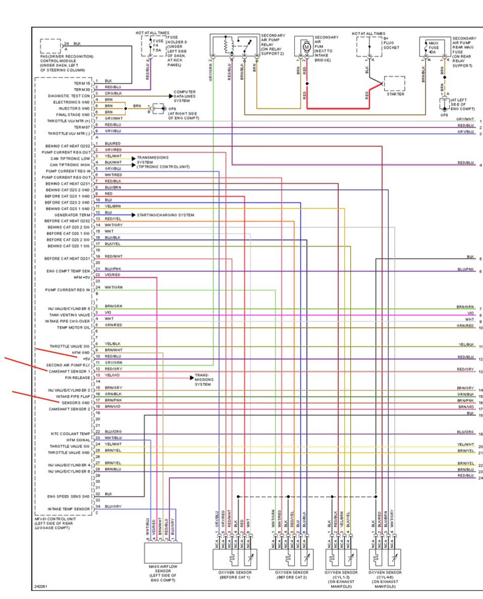
OK....Silly question...the diagram circled and posted shows from L to R....Red/Blu Red/Gry Brwn/Pink
If I'm looking at my connecter plugged in from L to R its opposite.. I have Brwn/Pink Red/Gry Red/Blu.
It is a used a car and evidence of peeps being in there already....I think.

-
My diagrams different unless I'm not understanding correctly. Ill post the one im looking at.Im troubleshooting wires #10 #12 and #17 from DME. I am seeing a fluctuating
5-8v on pin 12 with engine running. I see 12v on same pin with only key energized. Im backprobing + wire on multimeter to whatever pin on sensor plug im testing at the time(pin 10 or 12) and (-) going to common ground on engine block. I might add I saw 12v STILL on pin10 red/blue with the plug unplugged at the DME with key energized ..this led me to believe the power was coming from a different source other than DME(It was unplugged)
Maybe I'm on a completely incorrect diagram?

-
Im back!! So I figured let me go backwards one step at a time. I left the red/gry splice in and returned the red/blu back using original loom wire. Car started and ran no problem with exception of the same CEL p0010 triggered almost immediately. Cleared it and now getting pending p0010. Tested voltage:
Ignition on. Red/blu 12v
Red/gry 12v
Engine Running. Red/blu 12v
Red/gry 5-8v(fluctuating)
Totally boggled,does this mean
red/gry is the signal wire being the voltage is changed when running( from 12v to 5v)? Diagram shows red/blu at 5v. Brn/pink is ground. What next ?
-
Any truth in disconnecting batt for an hr to hard boot the DME or is that an urban myth.
-
Hey John...thanks for getting back. Im sure about tracing wires to the harness pins 10 and 12 for the wires i spliced. Correct volages at cam sensor plug. I don't know if they pass thru another device ...from the looks of the diagram it dosent look like they do. Wires are still there i can revert if I have to.
-
Ok now I went into PANICK MODE. I did what I said what I was going to do...essentially replaced the red/blu 5v wire between the DME and cam pos.sensor plug and FAILURE car dosent start. Tested voltage to red/gry wire and got nothing ...supposed to be 12v. Figured I disturbed an already failing wire...replaced wire between DME and plug and now have my 12v on red/gry 5v on red/blu and ground on brwn/Pink wire (ignition on) and...FAILURE. Car cranks begins to turn over briefly but won't start. What the hell did i do. Checked all fuses in foot well the stereo fuse was blown somehow. Other than that they were all good. Please help. Thanks V
PS getting pending p0638,p2122,p2127 CELs. Throttle sensor
-
Ok well here's what I found:
Wire. Continuity. Resis. Vol.Drop
Red/Blu. No. Open. 7.4v
Red/Gry Yes. .3k. None
Brwn/Pink. Yes. .2k. None
Volts at DME and Sen.Plug Ignition ON
DME. PLUG
Red/Blu. 5v. 12.6v
Red/Gry. 12.8. 12.2v
Brwn/Pink. .9mv. 1.2mv
I guess the oddest is the red/blu with no continuity but voltage when energized. Maybe it goes to a relay? Let me know what everyone thinks. Bad harness or the DME goes back to Specialized ECU. Thanks V
Did some reading seems to me red/blu has a short to voltage cause that wire supposed to stay at 5v. So maybe try replacing the red/Blu wire from DME to plug. Correct?
-
Ok, I'll recheck and post findings.
-
Well wait a minute. If I measure what I'm getting out of the back of the connector at the DME(back test it) and it matches what I'm getting at the sensor connector then I know it's not the harness....correct? V
-
Ok...do you know the part number to replace the pins in the plugs on dme side and sensor side? Would rather just make a 3pin harness and pull the pins and run the harness rather than clip wires. Thanks v
-
Hi,Gettig back to my p00010 CEL ...can I just jump the wires from DME to the sensor (3 wires) to rule out the harness. Got strange results when testing continuity and using a tracer. One wire had no continuity but the same wire pinged when using an electronic wire trace. Explained in previous post. Thanks V
-
Thanks, Well the new sensor didn't change anything, threw a CEL after 145 miles. So guess it wasn't the sensor. I probed around w my new probe/tracer. Findings with engine running:
14v R/Bl right connector
12v R/Gy center "
Gnd Brn/Pink left "
Traced positive for all 3 wires from Connector to DME in the trunk(got a trace tone)
Positive continuity for all EXCEPT the R/Blu right wire. No continuity but there was a tone when traced. Don't get it. Any thoughts? Put everything back together and CEL disappeared. Thanks V
-
Well I decided to spend 22 bucks 1st and just replace the sensor. The old sensor I removed has a different bosch #. I removed bosch
0 232 103 057(Mercedes apparently)and installed
#0 232 103 092. Ran at idle for few mins CEL remained on. Should I clear the code see if it comes back or will it clear itself. Thanks V
-
Checked voltage at the connector. 2 outside pins are ground with the middle at 12v with ignition on. Car running outside pin went to 14.2v, 12v in the middle and ground on the last outside pin. So one ground goes over to 14v from the DME I guess. I separated the 1st 6" of the 3 wires and twisted them around and the results stayed strong. I'll put a tone each and trace it. From what can tell by looking at the diagram the wires go to a control box left of the steering column in the footwell. Any idea where the loom or harness runs? Thanks V
-
Well I went for a drive and the CEL was gone when I started the car. Does that mean it's intermittent and most likely a wire issue?
-
Emm...I'll try find resources online about checking voltage to the connector. See what I come up with. The angle changes when watching cam angle when I accelerate w my Durametric but I was never able to activate my solenoids with my durametric. This was discussed on an earlier thread. Thanks V
-
Ugh...where do I start. Can you point to any sources.
-
Yes...typo..so that would mean a wiring issue? So what is the course of action.
-
Hi All,08 Boxster.Getting a P00010 CEL code. Camshaft Sensor bank1.
Is replacing the sensor usually the solution? If I clear it, it comes back in a hundred or so miles. Car runs fine but I do think it lacks a bit pick up. I'll check the wires and connector. Is there a way to test the sensor to see if its bad.. Is it possible it's the variocam solenoid?
Thanks V
-
Good News !! Maybe tracking it tomorrow!! Thanks V
-
Hey JFP, I looked at the actual angle cam 1 and 2 on my Durametric. The values did change in both banks when I revved the engine 2500rpms or so. They were negative values... dunno what that means. See video thanks V
-
Oh ok sounds easy enough. "Actual angle for cam shaft." I see it on the Pic you posted. So if the angle changes my variocam is functioning. Should I see change 24 degrees or am I just looking for a curve when revving. Thanks big help as always.
-
Hmm..explain simple terms. Select Cam1/cam2 deviation.
Rev engine and I should see a intake increase 24 degrees over what the exhaust cam is. Correct...sort of made that up. The cams don't adjust until a certain RPM 2000 ish?
-
Okay Do I select.. cam pos 1 and 2 on the durametric? What is the spec? Is there a spec for % cam angle at a certain rpm? Thanks.

08 Boxster P00010 code.
in 987-1 Boxster Convertible Top Issues and Solutions
Posted · Edited by vza
It's a 987.1 05-07 repair manual. Forgot where I got it from. It seems I made a major blunder at diagnosing. Looking at the flow chart more carefully the red/blue originates from fuse box so I'm assuming 12v it then passes thru 8 other sensors ending at mass air flow and cooling water valve on each side. Red/gry goes to DME labeled cam sensor im assuming that's the 5v ref no other sensors and the brwn/pink passes thru 4 sensors and is a shared ground. Again ...order of wires looks reversed at my plug. L to R I have brwn/pink red/gry and red/blu in diagram it's opposite meaning the ground and 12v are reversed. I'll look at the Bank 2 connector see what order it's in. Rechecked voltage 12v red/blu red/gry 55mv (shoud be 5v ref). Brwn/pink gnd. At DME voltage on red/gry is 55mv where it should be 5v ref. This was the same on bank 2 cam sen.ref wire BUT with engine running they are both 7v. Cam 2 ref wire according to flow chart is brwn/vio my wire was brwn(unless vio was no longer visible) This point I'm stumped. DME was rebuilt from Specialized ECU Doctor.Thanks v