Welcome to RennTech.org Community, Guest
There are many great features available to you once you register at RennTech.org
You are free to view posts here, but you must log in to reply to existing posts, or to start your own new topic. Like most online communities, there are costs involved to maintain a site like this - so we encourage our members to donate. All donations go to the costs operating and maintaining this site. We prefer that guests take part in our community and we offer a lot in return to those willing to join our corner of the Porsche world. This site is 99 percent member supported (less than 1 percent comes from advertising) - so please consider an annual donation to keep this site running.
Here are some of the features available - once you register at RennTech.org
- View Classified Ads
- DIY Tutorials
- Porsche TSB Listings (limited)
- VIN Decoder
- Special Offers
-
OBD II P-Codes - Paint Codes
- Registry
- Videos System
- View Reviews
- and get rid of this welcome message
It takes just a few minutes to register, and it's FREE
Contributing Members also get these additional benefits:
(you become a Contributing Member by donating money to the operation of this site)
- No ads - advertisements are removed
- Access the Contributors Only Forum
- Contributing Members Only Downloads
- Send attachments with PMs
- All image/file storage limits are substantially increased for all Contributing Members
- Option Codes Lookup
- VIN Option Lookups (limited)

Orient Express
-
Posts
680 -
Joined
-
Last visited
-
Days Won
3
Content Type
Profiles
Events
Forums
External Paint Colors
Downloads
Tutorials
Links Directory
Collections
Classifieds
Store
Posts posted by Orient Express
-
-
Do you mean like a flower petal or an accelerator pedal? :eek:
-

I am more interested in how Orient lifts his 996--did he hold back on his DIY on this subject, or is the car so clean it levitates?
--Brian
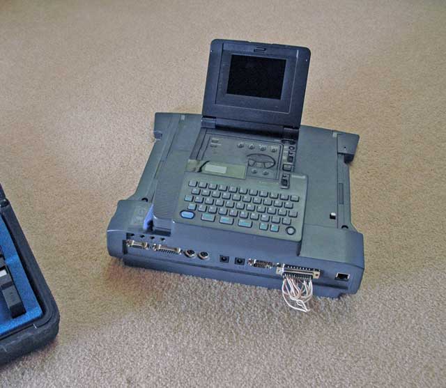
I use a government surplus GPL-693-a Mk2 levitator that I picked up at an auction in Nevada. It was designed for 400Hz power for moving aircraft around, but I re-wired it up to run on the cigarette lighter plug.
It is great for holding up the car when I do work on it.
-
I was washing my car today and saw that the engine was getting a bit dirty and greasy. Any tips on what I should cover before I spray the engine with a mild cleaner?
Thanks for the help.
Adam
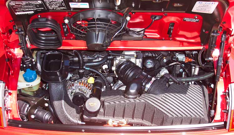
If you just want to clean the top half, then the easiest way is to spray it down real good with a cleaner like "Simple Green", let it sit for a few minutes and then hose it off. Make sure the engine is cold, or you will get a lot of steam in your face. While wrapping connectors, etc. in saran wrap certainly is a conservative approach, no harm will come to your engine if you hit it with water from a hose.
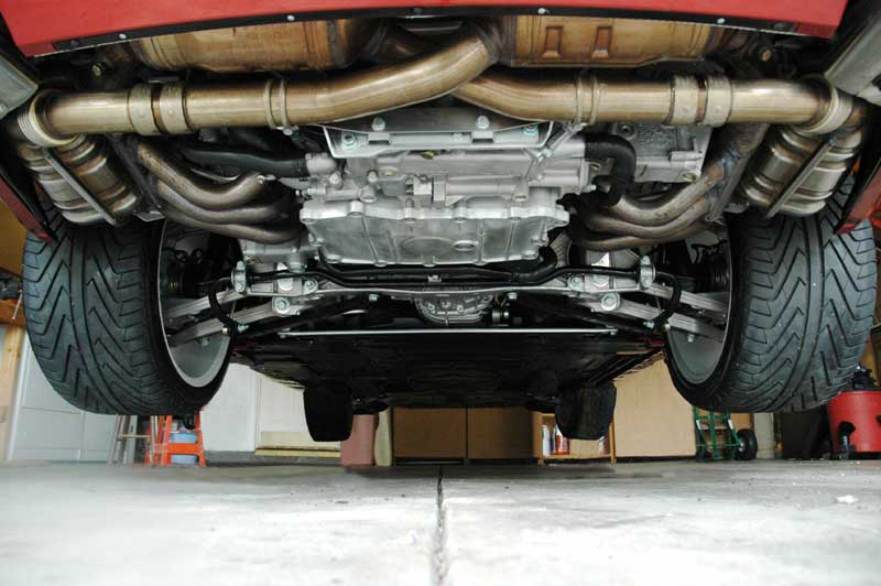
The underside is another matter. Unless you plan to show your car in a Concours, then it is probably just as well to leave it alone. The factory spray of cosmoline is pretty tough, and takes a pressure washer, a good nylon scrubbing brush and a solvent (like mineral spirits) to get it off completely. Given that in your neck of the woods, the environment is pretty harsh, especially in the winter, it is best to leave it alone.
However if you do decide to take the plunge, here is what you can end up with:
Granted, this car has 42K miles on it, so it is not as nice as it could be.
:thumbup:
-
Use an inline FM modulator. It is the best of a bad solution. Here is one from Crutchfield for $29.00
-
Can anyone confirm what connections run between the CDR23 and the appropriate changer? Is the audio carried by fiber or regular RCA cables? I was wondering if installing a CD changer might allow me to do the Aux In "trick" where you allow the CDR23 to control the changer but feed the actual audio from another device.
I have an 03 Boxster S with CDR23 and Bose if it is relevant.
Thanks, Chris.
On the CDR 23 the audio and control signals are digital via the fiber cable. Good thought, but not gonna work.
-
If you did not install the speed sensor wire then the cutout at 29 through 35 would not happen. If you go back in and cut the pink wire that will disable the speed cutout.
If you don't want the loud sound at low speeds, then turn the quiet mode on when you leave the house.
-
Sorry charlie, the only solution short of replacing the entrainment electronics is an in-line FM modulator. You have a MOST digital bus system, and there are no accessories out there yet for interfacing a iPod or mp3 player to the radio.
The biggest downside of the inline FM modulator interface is that you are limited to FM band frequency response and dynamic range.
But the only other variant of this available is the outboard FM transmitters which are useless in urban areas that have a lot of FM stations.
-
The way that I ran the wires is from the driver's side footwell, along the drivers door sill under the threshold cover that has the trunk and engine lid controls on it, then tucked in the seam on the rear seat side panel (the one with the speaker in it.)
Next take off the cover behind the rear seats. It is just held on with 2 screws. After routing the wire up along the bottom of the side panel you can go over and through the roll bar actuators in the middle and then back to the grommet. you will be able to hide the wire along this route no problem.
Take a look at my DIY write-up Here.
-
OK, you did the hard part of routing the 2 little wires, and you have the felt cover off of the back area. Now feel around on the soundproofing in the area behind the passenger seat, and you will feel a little round rubber grommet ("B" on the diagram) that covers the hole that you need to route the wires through. BTW, don't put the connector on the wires until you have them run to the engine area. It won't fit through the hole with the connector on!
Once you have located it, use an xacto knife to cut through the sound deadening to expose it. once you can see it, take your knife and cut an "X" in the middle of the grommet. (do not remove it).
That is what you will route the 2 little wires through to the solenoid switch. You will be able to grab the wires from engine bay to complete the routing. I would also recommend that you get some of that plastic cable tubing to protect the wires in the engine compartment. Once you have it all routed, then solder on the connector pins, and assemble the connector.
And with that you will be done!
-
I'm installing the electronics for my PSE and there are two wires that I am a little lost with. Hopefully someone who has been through this can help.
The instructions state:
1) Hook the GR/BL/BR wire "To jumper plug 5/2 (slot 28)"
and
2) connect the RE/BU wire: "Crimp to wire BK/RE; 1.52 for fuse B10"
The second one is a little easier, I guess I cut off the connector that is at the end of the RE/BU wire and hook it up to this wire behind the fusebox, connected to fuse B10.
The other one is a little weird, I'm not sure where "jumper plug 5/2" is. I already connected a brown wire to slot 28, but this three colored wire doesn't match any of the other wires in slot 28, they are ALL brown and it seems a little weird putting this other color wire to connect it to about 9 other brown wires.
Thanks for any help.
navin
Navin:
I had the same question on the PSE install on my 02 C2. After looking at the Relay support schematic I found that the step "Hook the GR/BL/BR wire "To jumper plug 5/2 (slot 28)" is an error for 02 cars and possibly later cars as well. Instead of slot 28, take a look at slot 25 instead. What the GR/BL/BR wire is for is the hot lead to the PSE switch illumination. On my car the switch illumination power supply is in slot 25, jumper plug 5/2
Slot 25 is bottom row 3rd position from left side. jumper plug 5/2 is the upper right one. (looking from the front of the relay support bracket) It is marked, with tiny type.
You are right in that slot 28 is all ground junctions. If you hook up the GR/BL/BR wire up to ground, you will create a short that will blow your panel illumination fuse. (so don't do that! :) )
For the lead to fuse B10, there are enough spades in that position that you should be able to just plug in the wire.
Hope this helps
-
Also does anyone know what the deal is on a cd update? I heard that there actually was one out, however it was bank like 250????
Yes, there is an update, and it is $250. What you might want to consider is to find someone on the opposite coast from you, and go in together to buy the update CDs. The update contains 2 CDs, one for each side of the US.
-
ok I've been able to remove it, but now I wouldhave to remove the older of the gps antenna, I removed the 2 torx screws but it doesn't come of, it looks like it too large, should I remove one of the trim pieces one the left of the right to remove it?
I have to route the GPS antenna cable that's why I have to remove it.
thank you
Yes you have to pop up the left side defroster trim a bit to get the mounting plate out. The trim is just held in with spring clips, so just stick a putty knife under it and pry up a bit.
Routing the GPS cable down to where the radio is can be a tight fit. What I found worked for me was to tape the end of the cable to a clothes hanger wire and push it down between the defroster ducts and the back of the area where the radio goes. It is only 3-4 inches, but it is a very tight fit to get the connector through. The defroster ducts are soft and will move out of the way as you push the cable through.
-
What you are trying to describe is something called "Scotchguard Paint Protection film". It is a 40mil urethane transparent film that has an adhesive backing. This stuff is typically used for rocker panel or fender flair protection. It is also great for the tops of rear bumpers to protect from scratches when loading stuff into the trunk, and in the door thresholds as well.
You can purchase DIY kits in various widths from any auto paint supply store. I have a roll that is 12" wide and 84" long and set me back about $90. I use it on the leading edges of the rocker panel flairs, and on other areas that are prone to scratch damage. the 3M part number is 84911. It is also available in 4" wide rolls as well.
The old piece can be removed by pulling on a corner and working it off. Spraying a mixture of water and alcohol on the material can help speed to process. If you get it off in one piece, then it can be used as a pattern for the replacement material.
Most places that do the Stoneguard invisible bras can also do this sort of material. It is similar to the invisible bra stuff only thicker.
Hope this helps.
-
Today I installed the Becker part into the back of my CDR220. It works great and was very easy. I am using the headphone jack for the output and find that most of the volume needs to be adjusted at the IPOD with the CDR220 turned to max volume. Can I use a docking cable directly into the RCA jacks and will this allow me to control the volume via the stereo ? I have read the Belkin auto kit descriptions , This doesn't interest me. I don't need the charging capability in the car.
I thought I would give my own follow up. I found that I could use the Dock and plug the headphone to rca cable into the back of the dock and now my volume is strictly controlled by the stereo not the IPOD . Now I just need to find a cable that fits into the bottom of the IPOD and ends in the 2 rca jacks so I dont have to drive around with a docked IPOD on the passenger seat.
Any suggestions???
-
2004 Boxster S with Bose Amp and Speakers and 6 CD changer (P73 option, Sound Pkg, Bose (Digital)
Are there any additional inputs available on the back of the radio unit?
Trying to hardwire an aux input to the radio unit (ie. my iPod)
Don't like the i-Tunes option of transmitting through the FM
The 2004 Boxster is a MOST bus car. So your options are limited to over the air FM transmitter or the better option of an inline FM transmitter. Of course you could rip the digital system out, and put in an analog system, but that is sort of extreme.
There have been talk of MOST adapters that let the iPod emulate the CD changer, but as of today they are just talk.
sorry
-
Seems like this mod was written up for the 996 (even though its here in the 996/997 section). Has anyone done this mod on a 997 yet?
Unfortunately on the 997 the sound cutout is done by the DME CPU so there is no analog relay to bypass.
OK then. Can you whip me up a DME firmware upgrade? B)
Sure thing, no problem, can I borrow your PST for an evening? I'll whip up a patch in no time at all.
:thumbup:
-
Seems like this mod was written up for the 996 (even though its here in the 996/997 section). Has anyone done this mod on a 997 yet?
Unfortunately on the 997 the sound cutout is done by the DME CPU so there is no analog relay to bypass.
-
Hmmmm dealer called, they must be trying to get a jump on things. That said, anything on the 90k?
It is all in the DIY Carrera/GT3 maintenance checklists forum. the 90K is essentially the same as the 30K, which is the same as the 15K except the air filter gets changed.
-
I have the 80K service coming up on my 99 996. Is this something of a DIY or Dealer? I have been doing a search and I see nothing come up for this. Information would be appreciated.
Don't you mean 90,000 mile maintenance?
The mileage markers are 15, 30, 45, 60, 75, 90, 105, 120,.... miles for a 1999-2002 Carrera.
-
On the back top row of connectors on the CDR-220, there are 3 connectors, unplug them all, and then plug back in just the blue Becker connector in the 1st position. The other 2 are for the CD.
(if you don't get any sound out of your radio after this, then plug in the 3rd connector, on some cars that is for the outboard amplifier.
After that, you must then enable the Aux-in feature of the radio. To do that, consult your owners manual (or the instructions that come with the Becker cable).
-
Maybe the owner can get some of his sticker "Sponsors" to pay for getting the car repaired. But since we are jumping on this poor chap with both feet because of his ricey tendencies, I might recommend that he approach "Uncle Ben's " as a sticker Sponsor. or perhaps that San Francisco Treat - ......
No mercy :thumbup:
-
Good question because I want that one and I haven't found the part number for the glossy one (if it exists).
Several folks have taken the matte finish switch and clear coated them to get a shinny finish with excellent results.
-
Izzy:
All you need to do is to make sure that the O rings are wet with some soapy water so they can slide into place. I use the stuff you use to blow bubbles with that you get at the toy store to lube up O rings etc.
No magic here.
-
This was this guys daily driver. Tracking was an afterthought.


rejex vs. maguire's nxt?
in 996 Series (Carrera, Carrera 4, Carrera 4S, Targa)
Posted
Rejex without a doubt.
Click my signature to see the proof