Welcome to RennTech.org Community, Guest
There are many great features available to you once you register at RennTech.org
You are free to view posts here, but you must log in to reply to existing posts, or to start your own new topic. Like most online communities, there are costs involved to maintain a site like this - so we encourage our members to donate. All donations go to the costs operating and maintaining this site. We prefer that guests take part in our community and we offer a lot in return to those willing to join our corner of the Porsche world. This site is 99 percent member supported (less than 1 percent comes from advertising) - so please consider an annual donation to keep this site running.
Here are some of the features available - once you register at RennTech.org
- View Classified Ads
- DIY Tutorials
- Porsche TSB Listings (limited)
- VIN Decoder
- Special Offers
-
OBD II P-Codes - Paint Codes
- Registry
- Videos System
- View Reviews
- and get rid of this welcome message
It takes just a few minutes to register, and it's FREE
Contributing Members also get these additional benefits:
(you become a Contributing Member by donating money to the operation of this site)
- No ads - advertisements are removed
- Access the Contributors Only Forum
- Contributing Members Only Downloads
- Send attachments with PMs
- All image/file storage limits are substantially increased for all Contributing Members
- Option Codes Lookup
- VIN Option Lookups (limited)

Richard Hamilton
-
Posts
1,830 -
Joined
-
Last visited
-
Days Won
13
Content Type
Profiles
Events
Forums
External Paint Colors
Downloads
Tutorials
Links Directory
Collections
Classifieds
Store
Everything posted by Richard Hamilton
-
What Russ didn't tell you was that he is in the UK - hence no air pump was fitted.
-
 If it is a cracked or slipped liner, try Hartech (http://www.hartech.org/). Autofarm do the Perfect Bore (http://www.perfectbore.com/) SilSleeve conversion, but I think the Hartech solution is cheaper.
 -
Cruise Control Repairs
Richard Hamilton replied to GRS from Kzoo's topic in 986 Series (Boxster, Boxster S)
GRS Those outputs were from my first interpretaion of the schematic. Pin B - maybe I interpreted the schematic wrong - I obviously got D and G right (the other two outputs from the stalk), but it seems that B may be the opposite sense. Looking at it again, I can see that the switch must be normally closed, so you are getting the correct output. Pin F - I have a Tiptronic, so I can't check the clutch switch. To me, the schematic shows the clutch switch normally open, but I guess it must be normally closed. Therefore I think this must be correct on your car. The brake switch only has 3 terminals connected, but they are numbered 1, 2, and 4 - so that's where the confusion probably lies. It seems to me that the problem is with your control unit, and the lack of output from pin K might confirm that. It might be worth taking it out, opening it up, and checking for an obvious fault inside. From memory, the circuit board connects to the socket with an edge connector, so it might be worth checking that the pins are clean. Otherwise, maybe you could get a used unit from a dismantler - that's where I got one from for my retrofit.
-
Cruise Control Repairs
Richard Hamilton replied to GRS from Kzoo's topic in 986 Series (Boxster, Boxster S)
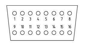
The green cluster light gets its feed from Pin K on the cruise module plug. This wire is also connected to pin 8 of the diagnostic socket, so you should be able to measure 12v+ at that connector with the ignition on, and the cruise switch depressed. Cruise Module: OBD2 Socket:
-
Cruise Control Repairs
Richard Hamilton replied to GRS from Kzoo's topic in 986 Series (Boxster, Boxster S)
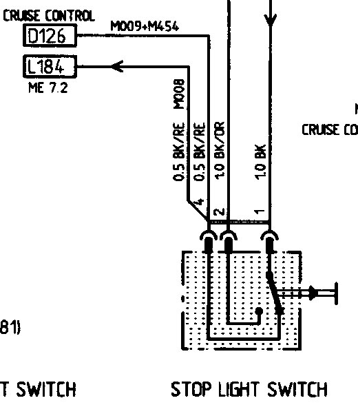
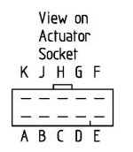
Sorry GRS, the spreadsheet just confused me. Maybe it’s just me that can’t interpret it, but what I think you are better checking is that you are getting voltages at the right places, rather than continuity. Pin H - Supply - should have 12v+ when the ignition is switched on. Pin D - Set/Acc - should have 12v+ when the ignition is switched on, the cruise switch is depressed on the end of the stalk, and the lever is pushed to set/acc. Pin B - Off - should have 12v+ when the ignition is switched on, the cruise switch is depressed on the end of the stalk, and drop to 0v when the lever is pulled to off. Pin G - should have 12v+ when the ignition is switched on, the cruise switch is depressed on the end of the stalk, and the lever is lowered to resume. Pin F - Clutch Switch - should have 12v+ when the ignition is switched on and drop to 0v the clutch is depressed. Pin A - Speed Signal - I think this is a pulse which will vary with speed, and would be difficult to test. If your other speed-related devices (spoiler etc) are working, I would assume this to be OK. Pin C - Stop Light Switch - should have 12v+ when the brake pedal is pressed. Pin J - Stop Light Switch - should have 12v+ when the brake pedal is up. Pin K - Signal out to the Diagnostic Socket & Cluster Light – the control module should give a 12v+ signal out when the ignition is switched on and the cruise switch is depressed on the end of the stalk. It should also have 12v+ for a few seconds when the ignition is switched on with the cruise switch off. The conecctor would have to be plugged in to test this. Pin E - Ground HTH. EDIT: Outputs to pin B and pin F corrected - see later posts - amendments are underlined -
IMHO it would be really useful if some of you guys could reply with which code Loren suggests actually works. It might help make more accurate predictions. Just my 2 cents worth.
-
Cruise Control Repairs
Richard Hamilton replied to GRS from Kzoo's topic in 986 Series (Boxster, Boxster S)
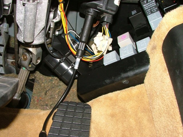
Does the green light come on briefly when you turn on the ignition? It should do. If not, it would be best to check that the actuator/control unit is getting a supply to pin H on the plug. This is my actuator, but bear in mind my car is Right Hand Drive. Excuse the wiring - it was before I got the correct plug when I did the retrofit. I'm sure it would be best to check the voltages at the plug.
-
Cruise Control Repairs
Richard Hamilton replied to GRS from Kzoo's topic in 986 Series (Boxster, Boxster S)
My cruise stalk switch problem is a long story, but it wasn't caused by a 'normal' failure. Thanks again to TP for helping me out there! I would start by checking the braks and clutch switches. The brake switch should be easy - do the brake lights work? You will need to put a meter on the clutch switch to see if you get 12v going on and off on pin 4 (yellow/green wire) as you depress the pedal. The clutch and brake switches can also slip in their mounting brackets and cause the plunger not to operate the switch. If it is nothing obvious with these two switches, I would pull the plug on the cruise actuator, and use a multimeter to test that you are getting the expected inputs, as shown on Loren's diagram. It will be easier to check the outputs from the stalk there, as you won't have to remove the steering wheel. -
Amazing, simply amazing!
-
Get some free advertising for his Calendar?
-
Order type help needed
Richard Hamilton replied to tholyoak's topic in 996 Series (Carrera, Carrera 4, Carrera 4S, Targa)
I didn't think there is a difference between the order codes of LHD and RHD RoW cars. I think they all end in "1". It will be interesting to know what the difference is. I did try other final digits (2-9) and the PET elways showed "Order Type Unknown". It would also be interesting to know the order types for the Turbo and GT2 variants if you have them. -
Take a look at the Interior Colour Code on the Vehicle Identifiation Label under the luggage compartment lid or in the maintenance booklet. If it starts with "C" it is probably Graphite Grey, and it it starts with "B" it is probably Space Grey. The colour codes in the PET don't tie up with the colour order codes in the order guides, but the first letters are usually the same. For instance, mine is Savannah - SP on the VIL, and S30 on the PET. (C60 is Graphite, and B50 is Space). HTH.
-
Order type help needed
Richard Hamilton replied to tholyoak's topic in 996 Series (Carrera, Carrera 4, Carrera 4S, Targa)
The order code is also printed on the VIL on the luggage compartment lid and in the service book. Hope this saves you a job: 996110 - C2 USA 996111 - C2 RoW 996120 - Anniversary (40 Year) USA 996121 - Anniversary (40 Year) RoW 996210 - Targa USA 996211 - Targa RoW 996310 - Cabriolet USA 996311 - Cabriolet RoW 996410 - C4 USA 996411 - C4 RoW 996430 - C4S USA 996431 - C4S RoW 996440 - Millennium USA 996441 - Millennium RoW 996610 - C4 Cabriolet USA 996611 - C4 Cabriolet RoW 996630 - C4S Cabriolet USA 996631 - C4S Cabriolet RoW 996810 - GT3 USA 996811 - GT3 RoW 996850 - GT3RS USA 996851 - GT3RS RoW -
New Twist on Garage Opener Hack
Richard Hamilton replied to joesan's topic in 986 Series (Boxster, Boxster S)
The radio antenna booster is at the bottom of the A pillar. You could easily tap into the feed for that. -
4 stalk steering column device
Richard Hamilton replied to willcapp's topic in 986 Series (Boxster, Boxster S)
Strange - I bought one from Porsch-Apart about 9-10 months ago for £70.00(GBP)+VAT. Also, they shouldn't charge you UK VAT (17.5%) if they are shipping out of the UK. I bought the stalk, a '99 cruise actuator and throttle pedal for £140+VAT+shipping. Just realised - maybe they were talking about brand new - mine was second hand. -
Radio Code
Richard Hamilton replied to chris_cambridge's topic in 996 Series (Carrera, Carrera 4, Carrera 4S, Targa)
Try 0531 If that doen't work try 0532 If that doen't work try 0533 If that doen't work try wait an hour because you will be locked out Then try 0530 Then try 0529 If no result, maybe someone has a better junk decoder than mine! -
PST2 - OBD2 and round 19-pin lead for 964/993 PIWIS 1 Tester PIWIS 2 Tester Autocom 2013.3 Bosch EsiTronic 2013 VAG VCDS BMW ISTA Location - Maidenhead, Berks, UK A bottle of dry white always goes down nicely! ;o)
-
Failed emission test
Richard Hamilton replied to Niclas P's topic in 996 Series (Carrera, Carrera 4, Carrera 4S, Targa)
I don't get any test options on my vehicle in the DME. Mine is RoW version 5.2.2, so maybe it is only available on US cars. That's a shame as it would be a useful function. -
What does my engine code mean
Richard Hamilton replied to Nick996's topic in 996 TT, 996 TT S, 996 GT2
If you go to https://techinfo.porsche.com/techinfo/index.jsp and select Great Britain>Genuine Parts Catalog, and download the catalog for the 996 Turbo, you will find it contains a description of engine codes and numbers in the V-Pages section. -
DME Replacement
Richard Hamilton replied to Paul Grainger's topic in 996 Series (Carrera, Carrera 4, Carrera 4S, Targa)
If the donor DME came out of a Boxster, it will have the Boxster map. The PST2 is used to program the DME with the appropriate map. I am not sure if the maps are stored in the PST2 and transferred, or they are stored in the DME and activated by the PST2, but any DME can be programmed for any variant, provided it is the same DME version. In other words, you can program the Boxster DME to the 996 map and immobiliser codes, as Todd confirms. Therefore if you can get all the codes from both the DMEs you have everything you need for someone who knows what they are doing with a PST2 to program the car. I would be interested to know how easy it is for you to get the codes from your dealer. Please let us know. edit: beat me to it Todd! -
DME Replacement
Richard Hamilton replied to Paul Grainger's topic in 996 Series (Carrera, Carrera 4, Carrera 4S, Targa)
I'll start by saying that I have never done this, but I believe it is possible. There are 3 Secutity Codes for the car: Immobiliser Code Teaching Code DME Programming Code These are stored on Porsche's IPAS system, and they record the codes against the VIN number. I think you would need all the codes from yours and the donor car. As I see it you would need to program the 'new' DME with the immobiliser code which matches the one in your existing alarm control module, and also program the 'new' DME with the correct fuel map for your car. When replacing the DME with a new one the routine is to read out the data from the old DME, replace it with the new one, and then program it to suit the engine, immobiliser, and catalytic converters. You also need someone with a PST2 who knows what they are doing! Todd Holyoak (tholyoak) has written several posts on the 986 forum about reprogramming DMEs for his 3.4 and 3.6 litre engine swaps. It would be worth you searching there for more info. -
Will this part fit ?
Richard Hamilton replied to WilliamsF1's topic in 986 Series (Boxster, Boxster S)
EWD is Matt black -
ABS fault codes?
Richard Hamilton replied to Reborn996's topic in 996 Series (Carrera, Carrera 4, Carrera 4S, Targa)
The workshop manual says: Front right speed sensor, open circuit/ short to ground/ short to B+ DTC 4200 General procedure as for test point 6/diagnostic trouble code 4205. - Speed sensor signal: Check with the Porsche System Tester 2 via the Actual values menu (call up front right wheel speed). - Internal resistance/continuity between PIN4 and PIN5 on the control module connector. -
Another OBC questions for the masters....
Richard Hamilton replied to mikes_box's topic in 986 Series (Boxster, Boxster S)
The wires don't already exist - you have to put them in yourself. That's why you use the VW wires, as they are a perfect fit in the cluster connectors. -
PCM1 (8bit) Codes
Richard Hamilton replied to Richard Hamilton's topic in 996 Series (Carrera, Carrera 4, Carrera 4S, Targa)
I haven't been able to check this myself, because my friend is a long way from me, and I'm not back in the driving seat yet. The car had some work done by a specialist workshop in Germany to get the car running, and they got the radio working but not the satnav. Apparently, there was a 5 digit code stored in the DME, which they gave my friend, but that sounds highly suspect to me. My understanding now is that there are two codes - one for radio and one for satnav. I guess the next step is to take out the nav unit and try the junk decoder with the serial number. I was hoping that he may be able to get the serial number by pressing a button, as can be done with some of the Becker radios. I assume it is made by Becker, but have a nagging doubt that it might be a Siemens unit, although I have no memory of where that thought came from.