Welcome to RennTech.org Community, Guest
There are many great features available to you once you register at RennTech.org
You are free to view posts here, but you must log in to reply to existing posts, or to start your own new topic. Like most online communities, there are costs involved to maintain a site like this - so we encourage our members to subscribe or donate. All subscriptions and donations go to the costs operating and maintaining this site. We prefer that guests take part in our community and we offer a lot in return to those willing to join our corner of the Porsche world. This site is 99 percent member supported (less than 1 percent comes from advertising) - so please consider an annual subscription or donation to keep this site running.
Here are some of the features available - once you subscribe RennTech.org
- View Classified Ads
- DIY Tutorials
- Porsche TSB Listings (limited)
- VIN Decoder
- Special Offers
- Paint Codes
- Registry
- Videos System
- View Reviews
- and get rid of this welcome message
It takes just a few minutes to register, and it's quality Porsche information at a low cost.
Contributing Members also get these additional benefits:
(you become a Contributing Member by subscribing or donating money to the operation of this site)
- No ads - advertisements are removed
- Access the Contributors Only Forum
- Contributing Members Only Downloads
- Send attachments with PMs
- All image/file storage limits are substantially increased for all Contributing Members
- Option Codes Lookup
- VIN Option Lookups (limited)


Schnell Gelb
-
Posts
309 -
Joined
-
Last visited
Content Type
Profiles
Events
Forums
External Paint Colors
Downloads
Tutorials
Links Directory
Collections
Classifieds
Store
Everything posted by Schnell Gelb
-
Cranks but no start -Misfire
Schnell Gelb replied to Schnell Gelb's topic in 986 Series (Boxster, Boxster S)
Thank you Ahsai ! To help others follow I have separated the reply into distinct parts. " per the factory shop manual, we want to be at TDC compression when we time bank 1 (cylinders 1-3) and TDC exhaust when we time bank 2 (cylinders 4-6)."Insite. So we need to confirm the piston stage/compression/overlap in #1 .The tools required are mentioned in Posts above and alternative methods below.Best to double/triple check otherwise .... Below is a link that shows the cylinder numbering - so you know which place to put the TDC tool into ! Note the helpful comment by Loren comparing the M96 as fitted to the 996 vs the 986. We are discussing Boxster 986 here.Look for the color chart buried in a few Posts in this Thread below.See the April 12 post by Domiac to find the color chart.This is important because you must make the distinction between "TDC Compression" aka TDC firing = top of compression stroke and all intake and exhaust valves for that cylinder are completely closed and tht spark plug has just fired. TDC overlap (aka TDC Exhaust) is when all the valves are slightly open .Specifically, the 2 exhaust valves of that cylinder are almost closed and the 2 inlet valves are just beginning to open. There is one complete revolution of the crankshaft between the two events. If the chosen cylinder is at TDC and you need to know if it is compression or overlap you can refer to the chart or try using a leakdown tester on that cylinder. In theory TDC compression allows very little/no air to pass . TDC Overlap would allow air leakage through both the intake and exhaust systems because all the valves of that cylinder are slightly open. If you try the leakdown tester - compare Cyl #1 with Cyl # 4. When #1 is TDC compression, 4 is TDC overlap(slight leakage) .When Cyl 1 is TDC Overlap, # 4 is TDC compression.The color chart shows this clearly for our 6 cylinder engine. This dwg below shows the chains and cams for a 5 chain engine.The 3 chain is similar. It helps explain Ahsai's point about setting the timing and avoiding being 180 out.
-
Cranks but no start -Misfire
Schnell Gelb replied to Schnell Gelb's topic in 986 Series (Boxster, Boxster S)
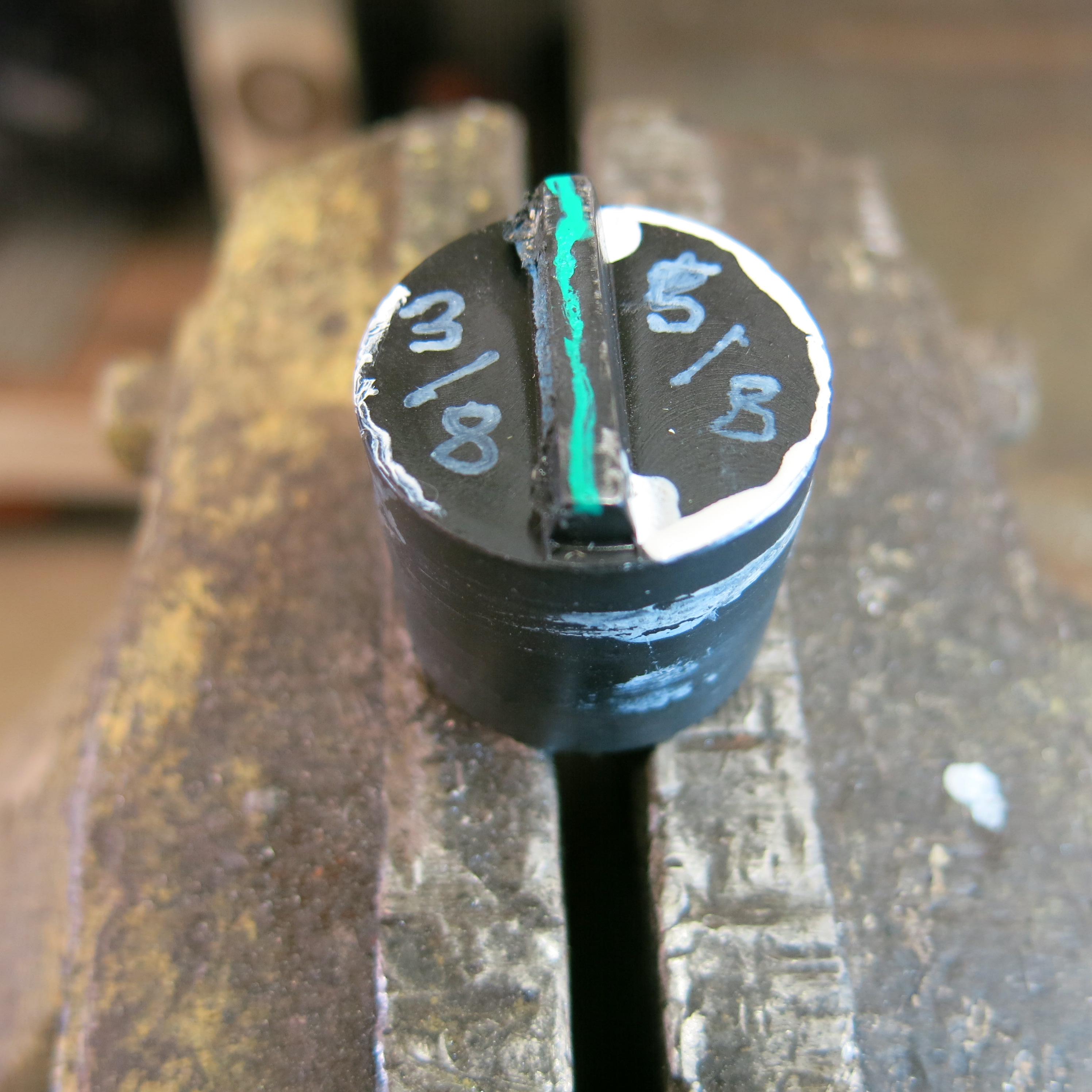
Below is a comparison chart of the Camshaft notch /Timing issue . The Chart has 3 columns and 2 rows. The top row is the Intake Cam notch position at TDC for Bank 1 and Bank 2. Note the "C" shape and its orientation -normal or mirror image. The bottom row shows the corresponding Exhaust Cam notches for Bank 1 & 2. The Exh Cam has a pair of OFFSET notches.These create to unequal segments. The left hand column is the usual starting point for checking cam timing. Lock the engine at TDC with the Bank 1 Intake cam notch at 3 p.m. , with the single notch facing away from the crankshaft/toward the Cam cover/outside of the car. This is shown at the top row of the left hand column. The diagramatic representation looks like the letter "C". Now look at the Row beneath this , the bottom row is the orientation of the Exhaust cam notches. Look at the bottom left dwg for Bank 1 -this is located close to the water pump area. It is viewed facing toward the rear of the car with the water pump on your right side. Note the smallest part of the crescent is adjacent to the Cam cover. The larger part of the segment is adjacent to the cylinder head. This cam cover/crankshaft orientation is noted on all the dwgs for clarity.Verify with Porsche tool # 9612-not eyeball. The center column shows the orientation of the Intake and exhaust cam notches on Bank 2 of the problematic "crank, but no start engine". Note the Ex cam notches are NOT a mirror image of Bank 1. This is my current situation verified by using Porsche tool 9612. The right hand column is a speculative, alternative (correct??) orientation . Which is the correct column? Jake Raby should use this as a Final Exam question for his M96/M97 engine rebuild class - oh how I wish I could attend it ! BTW , if you have a FSM the relevant Section/pages are 15-51 for the Inlet Notch 1-3 Bank 1, for 4-6 Bank 2 it is 15-23 & 15-69 . I think the "cranks but no-start " clue is in the center column, bottom row. It should be like the right hand column,bottom row. One other clue is the engine is stiff to rotate near TDC even with plugs removed (bent valves on the exhaust side of Bank 2?) I am hoping for a simpler explanation. How can one cam be 180 cam degrees out and the other 3 perfect ? This is the 'puck' from 9612 below.The rib is marked in green for clarity.
-
Cranks but no start -Misfire
Schnell Gelb replied to Schnell Gelb's topic in 986 Series (Boxster, Boxster S)
You are correct .The engine ran beautifully after Porschetech 3 kindly supplied the missing spring.It sailed through the Smog Test.Then the ticking and misfire began.And the misfire deteriorated to the point the engine barely ran .So I was thinking that collapsed lifters that may have been the cause of the Misfire . I discovered several new INA lifters had collapsed and could not be restored by pumping when immersed in oil. So I replaced them all.Yes, all 24 ,both sides. I wish I knew what else happened. Below is a photo of the puck from 9612 and the Cam Notch orientation chart. -
Cranks but no start -Misfire
Schnell Gelb replied to Schnell Gelb's topic in 986 Series (Boxster, Boxster S)
Ahsai, Thank you for responding so helpfully and promptly. I'll get right on it. I have already confirmed that all 4 cams rotate when the engine is turned over - hey you never know ! I do want to emphasize that the tool LN or Baum 9612 is the key to verifying the correct orientation of the Exhaust Cam notches with the engine in the Boxster. Using other tools particularly the flat "E" shape retainers can be misleading. They are virtualy impossible to fit with the engine in the car anyway.The smaller "C" shaped tool is also inadequate. This is the best link I could find to help others identify Porsche tool # 9612 among all the other Baum tools. http://www.ewktool.com/porsche-986-996-engine-timing-camshaft tool Click on the thumbnail photos until you find the tool.You need to extract and use just the black "puck" with the offset rib . It is the perfect go/no-go gauge for M96 Cam setting with the engine in the car. I recall you recommending a TDC compression whistle some time ago.Since I work alone, that may be helpful.Innovative Products # 7894 may work well. One challenging issue is the procedure for correcting the timing problem. The convention is to rotate until Bank 1 cam notches are correctly oriented and then to remove the Bank 2 cam cover to rotate it's cams to the proper position. The problem is that Bank 2 is more difficult to work on because of the a/c compressor obstructing the chain Tensioner and other obstructions. I may try to lock at TDC with Bank 2 correct so I can work on the easier Bank 1 side. To do that correctly it will be essential to use the cheat chart below to verify all 4 notch notch positions are correct. And use the whistle before replacing the cam cover ! Thanks again and I hope the extra details help others. -
Did you see the Pelican DIY ? Mine is a 6 speed so can't advize you directly but the Pelican Project book helped me when i re-booted and re-packed my CV joints.
-
Cranks but no start -Misfire
Schnell Gelb replied to Schnell Gelb's topic in 986 Series (Boxster, Boxster S)
In a Post much further down this page is a drawing explaining the problem. Hopefully it will save a lot of ambiguous words. The sketch needs better computer drawing skills than mine ! Feel free to improve them for other Forum members to understand & use.. Column 1 of the dwg is the starting point for all M96 camshaft timing. This Post refers to the 986 Boxster. There are some confusing differences with the 996 because of the backwards engine orientation there . I invite the 996 guys to plagiarize this and re-write for their needs. When we discuss problems with M96 timing we get confused with terminology ,orientation and engine positions. So why not use a picture? Just copy the dwg below and draw in your ‘notch’ positions when you remove the “green caps” Then it is much easier for the smart guys to help you. I am not in that group hence the clumsy sketches below. If the dwgs confuse you ,I suggest you read more of the basic camshaft timing Instructions first. Sadly we lost Insite’s images with the hosting problem. So this may help ? Basically it is all about camshaft notch positions at TDC. And specifically the confusingly similar right/wrong orientation of the2 Ex Cam notches. These dwgs help with checking a camshaft R&R with the engine still in the car. You CAN NOT see the camshaft notches directly because you can not get a direct line of sight. I have used a Smartphone on a selfie stick but such photos are useless unless you post alongside them all 4 positions. Nobody does this. Now you can- easily. The Inlet camshaft single Notch is easy to observe in the car. The difficulty is the Exhaust Cam notches. There is one trick tool = LN9612 required to confirm the position of the 2 asymmetric notches at the end of the exhaust camshaft. Do not try to eyeball this unless the engine is out of the car IMHO. You need just the black ‘puck’ from the 9612 tool with the offset ‘rib’ across it’s diameter. It will only fit one way on the end of the EX cam. Go /No Go. Just note which way round it fits and we’ll be able to confirm if you have reassembled your camshafts (in)correctly. Do not try to just use the cam retaining tool for this purpose unless you are an expert. I made that mistake several times and got lucky .More recently, my luck ran out…… I used the LN 9612 tool to make the dwgs below so it will be a good test to see if the experts can quickly diagnose my mistake.There is a photo in later posts of 9612. Do all these observations without rotating the engine. We need all 4 quadrants completed at the same TDC position. Once you have done all 4, you can rotate 1 full turn of the engine(not the cams - they rotate only 180 for each 360 of the crank)and re-draw. But note this in your Post. All my dwgs below are in the same ,locked TDC position. Bank 2 is the problem. You need to observe and note the Inlet cam notch via the Access Plate in the Firewall. Maybe feel it from underneath ? See dwg for details. The greater difficulty is the Exh. cam notches because of obstructing cross-member and other parts. You can’t get even close to a direct line of sight and no other tool except the puck will fit correctly. Yes, I tried ! Dwg shows the orientation on my “Cranks ,but no start” engine rebuild. Note the notches are deceptively vertical BUT the important distinction is where the smaller segment of Bank 2 Ex cam is . Is it closest to the Cam Cover(outside of car) or the crankshaft(inside of car) ? Yes ,this is mind numbingly geekish but it will save you if you check this before you fit the Cam covers but after the Tensioners are refitted. I hope this helps. Feel free to improve for others to benefit. Did you spot the mistake btw? Here is a link to some useful photos from Nutrod for those unfamiliar: http://www.nutrod.com/Nutrod/Pics/Pages/Install_Head_4-6.html There is a great Thread by Insite on the 986 Forum but Photobucket dumped all his photos ! http://986forum.com/forums/performance-technical-chat/26418-diy-setting-cam-timing-m96.html -
Cranks but no start -Misfire
Schnell Gelb replied to Schnell Gelb's topic in 986 Series (Boxster, Boxster S)
-
Cranks but no start -Misfire
Schnell Gelb replied to Schnell Gelb's topic in 986 Series (Boxster, Boxster S)
Duncan, Thank you for your thoughtful and logical suggestions . I now have a great to do List . -
Cranks but no start -Misfire
Schnell Gelb replied to Schnell Gelb's topic in 986 Series (Boxster, Boxster S)
Danke schon ! All 6 injectors were rebuilt during the engine rebuild. I did buy a new one recently because I wanted to compare it with my rebuilt part. No difference. I fitted the new one anyway.It ran perfectly. Nevertheless, your suggestion is a possibility to investigate. Thank you. Edit : Wizard had a point regarding the Misfire.See below for flooding of cyl 1 with gasoline. Remedy is easy -6 new upgraded Bosch injectors. For once , a simple job on the M96 ! -
2001 Boxster S 6 speed, 3.2L, 92,000 miles - engine recently rebuilt with many ,many new parts. Ran well.It passed Smog then a few weeks/hundred miles later started developing P0300 misfire codes for all 3 cylinders on Bank 1. A few lifters were ticking and the engine barely ran , so I replaced all 24 lifters . Now it will not start and is over fueling. There is raw gas in the headers ! When I removed the Cams to replace the Lifters, I also found raw fuel in both headers. I assumed this was a symptom of Misfire caused by some collapsed lifters. There is plenty of fuel flow at the Test Port. The Crankshaft Position Sensor is new(for Smog Test) & the tachometer bounces when I crank the engine.All the dash warning lights illuminate correctly during cranking so I 'guess' the Ignition switch is O.K. The battery is new and tests perfectly. The camshafts rotate when the engine is cranked(remove green plugs) . The IMS sprocket was pinned to the shaft during the engine rebuild. I haven't checked compression but when I rotate it by hand on the crankshaft bolt(to check timing) it seems normal. All 6 coils and plugs are new and the car had these when it passed Smog recently. The SAI system was fixed prior to the Smog Test. I have not checked/replaced the camshaft position sensor. They seldom seem to fail. When the Bank 1 camshafts were off the engine I confirmed the 'window' for the camshaft position sensor was not bent nor loose. I can check to see if there is a complete blockage of the inlet system. I mention this because I did replace the Airbox with a CAI prior to the Smog Test and it ran well. I have checked many times that I reconnected (after replacing the Lifters) all the connectors for the Variocam solenoids, O2 sensors, oil pressure sensor, camshaft sensor,crankshaft position sensor. The car sat for around 2 months while I did the Lifter work. The Ignition key remained on the dash but not in the ignition switch throughout this period. The car was in a garage so the immobilizer did not get wet and has never been wet. The new battery remained fully charged throughout. I did do the Initialization procedure when I tried to start it but only after building oil pressure(remove fuel pump fuse C4). * Is there some technique with Durametric during cranking to help pinpoint the problem ? In the past, I have only used Durametric with the engine running.There are no codes yet because the engine will not start. There must be some Freeze Frame that would show a total failure of the Ignition system? What am I missing ? DME checks? Any helpful suggestions would be most gratefully received. Thank you.
-
Glad it worked for you . I have the same problem except I can not remove those screws behind the steering wheel. I have all the correct tools. The torx screw just spins. So I fitted Nautilus horn and a separate MOM horn button pending a resolution of the spinning screw problem..
-
This is very encouraging. We need more ppl/victims to try it ! That way we can build some experience of when/why it works and what is the best hard reset method. Thank you for sharing with us.
-
Foam Pieces in Defrost Vent
Schnell Gelb replied to Wausau 911's topic in 996 Series (Carrera, Carrera 4, Carrera 4S, Targa)
We have 2 Threads on exactly the same topic simultaneously.May be a good idea to merge them? -
For those in hot climates only. Look at the photo above clearly showing the 2 heater core hoses ? Suppose you disconnect both hoses and splice then together. Fabricate a U shaped fitting from copper plumbing elbows? You could use a "Y" fitting & add a air-bleed fitting ! That may help the warm a/c problem yet maintain normal circulation in the engine cooling system. Cap off the 2 open tubes to the heater core temporarily. For those who say I have foam debris but no problem with a/c - that is because only one of the 2 flaps/doors has begun to disintegrate. The other will surely follow !See Ahsai's helpful system description in a previous Post in this Thread. In winter reconnect the hoses? Check "Meir" on 986 Forum who did a great write up/Thread- see below.http://986forum.com/forums/diy-project-guides/37246-c-evaporator-replacement-c-foam-flakes.html From Ahsai: "If you look at the photos here, you will see there are two flaps covered by the foam. http://986forum.com/forums/324153-post11.html One flap controls the temp (blocking air from entering the hot radiator that's not shown in the photo) and the other diverts air to diff vents. So if the loose foam is coming from the former, your air temp may get affected. If the foam is coming from the later, air flow will be affected. So depends. I think there's not much you can do at this point other than just wait and see and address it only if needed. It's a HUGE job. The dash has to come out..."
-
Thank you for taking the time to add to our (still incomplete) understanding of the Vario Cam/DME system. What we lack now is an explanation of why your CEL required a hard reset to clear. It is also worth noting that some were skeptical about the usefulness of a hard reset. I am just putting cam covers back on for a second time and am wondering if I should have tried a hard reset. Why? Because like you, I found no problems and the engine has less than 1000 miles on a total rebuild. Guess what I'll do if the CEL persists :-). Thank you !
-
This may get you started: http://www.pelicanparts.com/techarticles/Porsche-996-997-Carrera/08-ENGINE-Carrera_Engine_Tear_Down/08-ENGINE-Carrera_Engine_Tear_Down.htm http://workshop-manuals.com/porsche/911_carrera_4_cabriolet_(996)/f6-3.4l/engine_cooling_and_exhaust/engine/cylinder_head_assembly/valve_cover/component_information/service_and_repair/page_1628/
-
One point to note is that if you do a camshaft R&R with the engine in place, Bank One is much easier than Bank 2. The big issue is access - for example the Tensioner for Bank 2 is under the a/c compressor and other tubes/pipes/hoses and fittings interfere.Then there is the Airbox ! A much bigger problem is that it is very difficult to verify the sprockets and chain retain their setting - 7 links apart - while struggling to refit the cams to the cylinder head. I used a white paint Marker pen to highlight the 'divots'. My chains did not have different colored links so I marked them on the bench with flourescent green paint Marker. I suspect some of the large degree Deviation problems may be caused by the chain slipping 1 tooth on one of the sprockets. I think the math works out to roughly a 10 degree Deviation. If this happens, it is one helluva lot of work to dismantle and verify !!! Someone did hint that it is better to drop the engine +/- transmission that do this job with the engine in place.... He did have a point I now realize :-). Oh and btw, Deviation is to be measured only with the engine fully warmed up.
-
Rough idle, loss of power on accelleration, IMS?
Schnell Gelb replied to BrianH's topic in 986 Series (Boxster, Boxster S)
You might want to try doing a "wet" compression test on #6 or a leakdown test. That may help you identify the source of the low compression woops, Great minds... -
For any student of Porsche Variocam diagnoses ,this was an interesting contribution to the Forum wisdom on the subject.Thanks for the time taken to document all this for us. Fortunately the O.P. was adept at both the electrical and mechanical tasks required for both diagnosis and repair. A superficial diagnosis would have indicated a defective solenoid from the Durametric Actual Values ,the 13 ohm Resistance test,the click test with a 9v battery Fortunately the P.O. also identified the fundamental cause of the problem to be a defective solder joint in the DME. He concluded that was causing an over-current to one solenoid. If he had simply replaced a defective (very expensive)solenoid , his repair success would not have lasted long. And how many times would the repair cycle have been repeated before the root cause was identified ? Opening the DME as part of Variocam Solenoid diagnosis seems like a good idea ! Carefully pry of the cover from the disconnected DME and smell it+ look for small burn areas.For those who do not have the skills to repair solder joints on the DME board, the only repair resource I have seen on the Forums is Specialized ECU Repair. They charge almost $700 for a replacement ECU .So those soldering skills were very valuable to the O.P. ! Unfortunately the Solenoid windings were beyond repair. Thanks Talkenrain and may your Variocam System be eternally perfect.
-
Passing Smog so soon after so much dismantling was amazing. It will be interesting to read the follow-up . Leaks, ticking, Durametric readings. Wishing you an uneventful report ! BTW , on the farm we used "Udder cream" or "Bag Balm" on our hands. Cold, wet weather+dirt from repairing farm equipment in the field =never a good combo.
-
Elusive Rattle
Schnell Gelb replied to Hilux2400's topic in 996 Series (Carrera, Carrera 4, Carrera 4S, Targa)
There is a tool for this problem.It requires a co-pilot to operate it. Search for "Chassis Ear"in U.K. Here is the Colonist Version -
The most important challenge is to get a center punch divot dead center. If it is off, the left hand drill/easy out - whatever you subsequently use may damage the aluminum threads. Usually the first step is to use a guide but there is nothing to center a guide on. In you cse where it snapped flush, the first challenge if to try to file(careful!) the steel bolt center - flat so you can mark it with the punch.If it is not flat ,it will skip off center. This is a useful reference: https://www.stomskiracing.com/products/exhaust-head-stud-repair-kit Your Machinist guy may have something similar. You may be able to use the exhaust manifold as a guide if you also use a sleeve?Use cutting fluid Measure your threaded hole carefully add for the manifold flange+ gasket+nut + a little and calculate the length you need .Something similar(???) to this. http://www.ebay.com/itm/14-Piece-M8-x-1-25mm-x-35mm-A2-70-Stainless-Steel-Exhaust-Manifold-Stud-Kit-/232327237709?hash=item3617c8504d:g:TiAAAOSwi7RZD-9j&vxp=mtr
-
I have but one request of you in repayment for these hours of help. Test your new HF 1/4 T. wrench against your 3/8 one and tell us what you find.
-
Tekton get could results from the comparisons on YT . Solid recommendation on that basis.
-
Don't tell JFP. :-) Seriously-it is better than nothing. But as Ahsai advised practice with it on junk first. We really do not want to be helping you do helicoils/timserts.