Welcome to RennTech.org Community, Guest
There are many great features available to you once you register at RennTech.org
You are free to view posts here, but you must log in to reply to existing posts, or to start your own new topic. Like most online communities, there are costs involved to maintain a site like this - so we encourage our members to subscribe or donate. All subscriptions and donations go to the costs operating and maintaining this site. We prefer that guests take part in our community and we offer a lot in return to those willing to join our corner of the Porsche world. This site is 99 percent member supported (less than 1 percent comes from advertising) - so please consider an annual subscription or donation to keep this site running.
Here are some of the features available - once you subscribe RennTech.org
- View Classified Ads
- DIY Tutorials
- Porsche TSB Listings (limited)
- VIN Decoder
- Special Offers
- Paint Codes
- Registry
- Videos System
- View Reviews
- and get rid of this welcome message
It takes just a few minutes to register, and it's quality Porsche information at a low cost.
Contributing Members also get these additional benefits:
(you become a Contributing Member by subscribing or donating money to the operation of this site)
- No ads - advertisements are removed
- Access the Contributors Only Forum
- Contributing Members Only Downloads
- Send attachments with PMs
- All image/file storage limits are substantially increased for all Contributing Members
- Option Codes Lookup
- VIN Option Lookups (limited)
-0001-0001.png.112c13ee97acfad0cb1e70d195cc9a0e.png)
Loren
-
Posts
37,871 -
Joined
-
Days Won
640
Content Type
Profiles
Events
Forums
External Paint Colors
Downloads
Tutorials
Links Directory
Collections
Classifieds
Store
Everything posted by Loren
-
-0001-0001.thumb.png.17f5bb25bf8ec261a17c21e6321c8492.png) Then one of your sensors is not likely completely plugged in.
Then one of your sensors is not likely completely plugged in. -
Retro Fitting Multi Function Wheel controls
Loren replied to berty987's topic in 987-1 Series (Boxster, Boxster S)
Just a word to the wise - there are some "electronic" options on the newer car that Porsche has locked down with access codes. So anyone with a PIWIS may not be able to just turn on a function. Instead they would need to contact Porsche (showing proof of payment) and then getting the access code to turn the function on. I know this is true on the Cayenne Compass option. -
If you wan the Porsche one - it is in a TSB. Tool Pants (et al) did a DVD that covers the whole thing too. http://www.renntech.org/forums/index.php?s...ost&p=18034
-
Part Number for MY02 Carrera 4 Cab Battery
Loren replied to 996guy's topic in 996 Series Part Number Requests
Porsche Battery - $194.39 (retail) Autozone Duralast - about $69. http://www.renntech.org/forums/index.php?s...ost&p=14446 -
Please do a search here - it's been covered many times.
-
If it were my car I would start by removing and cleaning the throttle body. I've seen several egas Boxsters that idle poorly and 98.0% of the time it has been a dirty throttle body.
-
Is this a US car? Where are you located?
-
Not really - like the quote says that pump runs for a max of 179 seconds (just under 3 minutes). These engines are already putting outs lots of HP/liter as it is. (IMHO) With late model Porsche's there is not much to be gained with mods. If you want a lot more power you move up to a GT3 or TT. The TT responds pretty well to specific mods - but then you have to ask yourself if you really need 750-800 HP (and can handle it).
-
Bought a 2003 C4 Cab, roadtrip home!
Loren replied to jsmirand's topic in 996 Series (Carrera, Carrera 4, Carrera 4S, Targa)
:welcome: -
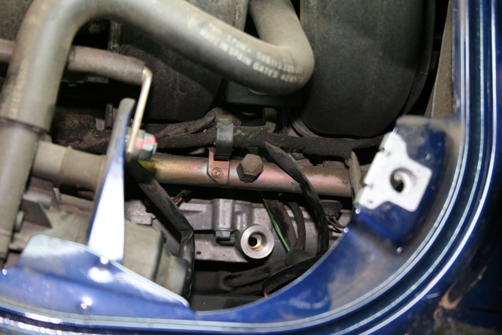
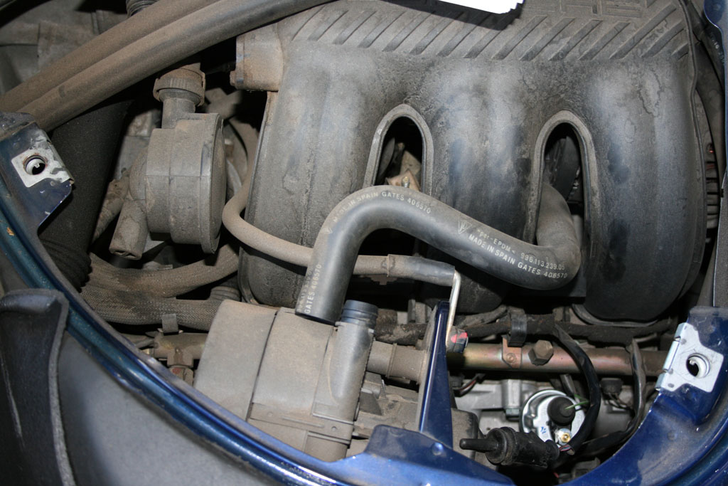
More than you likely want to know... "Auxiliary Air Pump To reduce pollutants contained in the exhaust gas during the warm-up phase and to achieve the emission limits of the roll test in the USA, USA vehicles have a secondary air system. For this reason, an electric air pump has been mounted on the left-hand side of the engine compartment. This pump is activated by the DME control unit and blows the additional air through air ducts to the discharge valve. A pneumatic switching valve which is closed when the secondary air system is inactive thus preventing the flow of additional air is installed between the air pump and the discharge valve. Functioning If the engine is started in a temperature range between minus 10.5° C and plus 45° C, the secondary air system is activated for a period of time dependent on the start temperature (min. 50 seconds, max. 179 seconds). The secondary air system is only activated if the following engine-related operating conditions apply: - Engine load (TL) between 0.7 ms/rev, and 4.7 ms/rev. - Air mass (ML) not greater than 300 kg/h - Engine speed between 680 rpm and 2,800 rpm - Altitude adaptation factor greater than 0.76 corresponding to less than 2,400 meters above sea level."
-
OBC with 04 C4S cluster in 01 Boxster S
Loren replied to LowFlyR's topic in 986 Series (Boxster, Boxster S)
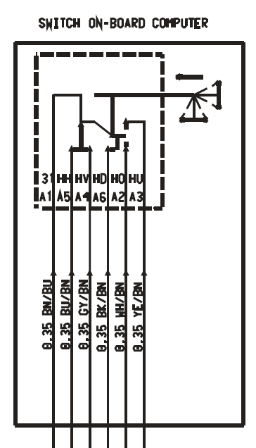
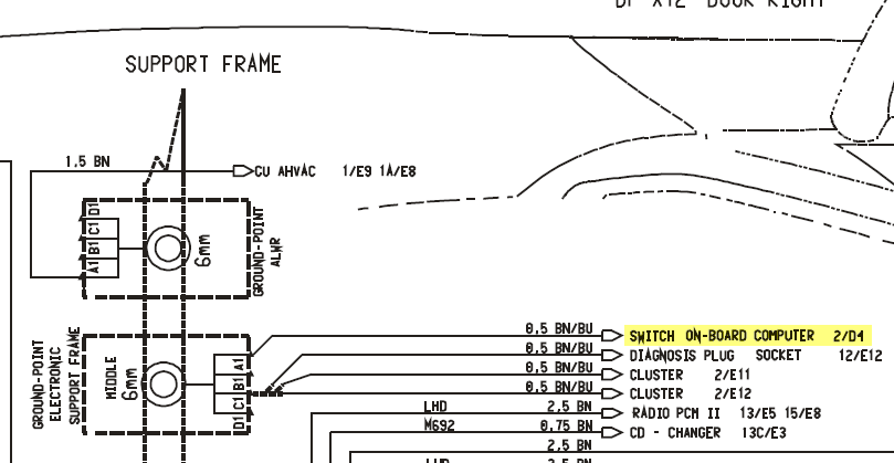
On a MY02 and newer cluster there 6 wires to the OBC not 5. Pin A1 (Brown/Blue) off the stalk needs to go to component ground.
-
Carrera Instrument Cluster Transplant To Boxster
Loren replied to whall's topic in DIY Articles - Boxster (986) - Mods
Bill, Just to be clear - Anne will need to find a (in her case) MY02 or newer C2 cab so that I can perform the programming. Since your procedure includes "3. Open (or close) the top slightly so the top cover is out of the closed position," - it can't be programmed using a coupe. Correct? -
NAV and CDC-4 from burned C2S
Loren replied to soV's topic in 997-1 Series (Carrera, Carrera 4, Carrera 2S, Carrera 4S)
On the left is the CD Changer with 6 pins. A1 = 1 A2 = 2 On the DVD Player - would be easier if you had the connector (as it is likely numbered). A1 should be ground and chassis ground - so if you take an ohm meter there should be zero resistance between pin A1 and the chassis. If I had a first guess I would guess the top right pin in your pic is A1. A2 should be the next pin in the A1. On the DVD Player only A1, A2, and A5 are used. A3 and A4 are for diagnosis so they are not normally connected. And A6, A7, and A8 are not connected. -
NAV and CDC-4 from burned C2S
Loren replied to soV's topic in 997-1 Series (Carrera, Carrera 4, Carrera 2S, Carrera 4S)
That could be a real challenge. The 997 NAV and CDC-4 communicate with fiber optic cables (MOST network). Did you salvage those too? On the DVD Player A1 is ground and A2 is power. You will need the fiber optic cables off B1 and B2 also. On the CDC-4 A2 is ground and A1 is power. B! and B2 are fiber optic again. With that said I have no idea if they will function onside of the car over the network or if they still need at least one network controller. Let us know how you make out... -
Diagnostic Tool for both BMW and Porsche?
Loren replied to Hobbes's topic in Diagnostics, Tips and Diagnostic Tools
The Durametric Tool does some special things with Porsches that factory tools costing thousands of dollars can do. So I don't thing you can compare that to a more generic ISO tool. If you need the features of the Durametric software then you might want to consider it plus the Car Code OBD-2 Vehicle Explorer Scan Tool that I reviewed here.
-
NAV and CDC-4 from burned C2S
Loren replied to soV's topic in 997-1 Series (Carrera, Carrera 4, Carrera 2S, Carrera 4S)
Sorry, guys the 996 wiring is not even close to a 997. 997 series cars have easily 10 times more CAN (network) and CAN controllers - that all interact. Apples and Oranges really. -
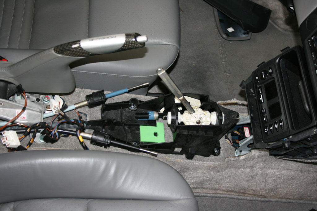
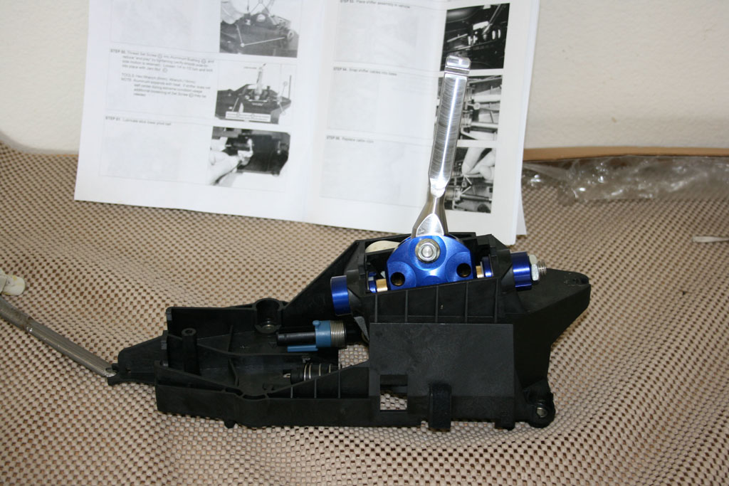
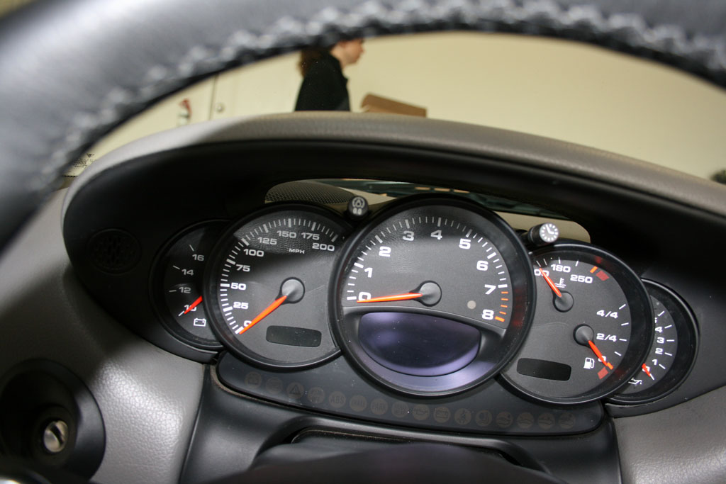
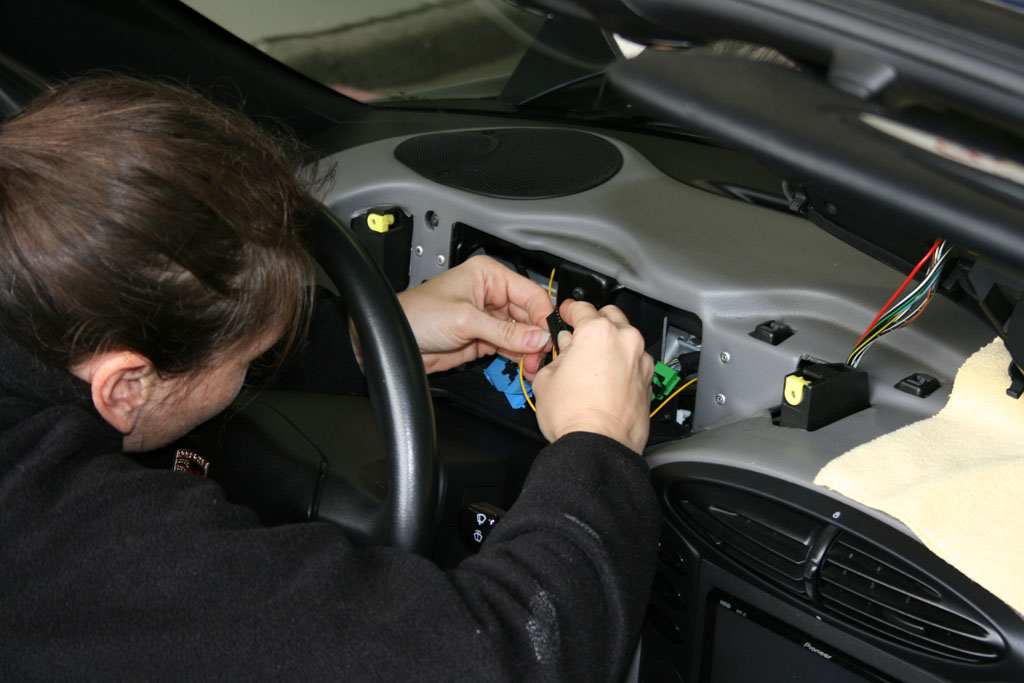
A few pics from yesterdays Work Cars Day... Can this be a Boxster cluster? (project 1) Done a few of these too... Once again proof of how easy these cars are to work on... Back to that cluster... (installing a 996 cluster in a Boxster) Adding one wire from the cluster to the engine compartment oil pressure sending unit Where the new (996) sending unit goes... Installed and wires connected MY2001 Boxster with a fully functional 996 cluster and a B&M short shifter. Special thanks to Anne (she did most of the work - including providing lunch) and Rich (who took most of the pics). Anne is pretty good at this stuff I think she could give Eileen in the Bay Area a good contest :lol:
-
Mike your list is out of date. The latest Approved Oils List is dated April 11, 2007.
-
Try 6781 or 6779
-
You can download your radio owners manual here.
-
It was an option. Option M476 - Porsche Stability Management (PSM).
-
You need to give us your radio serial number not your car's VIN. If you read through some of the posts here (in this thread) you see how to get your serial number to display. http://www.renntech.org/forums/index.php?s...ost&p=74043
-
Porsche and Volkswagen to cooperate further: paper
Loren posted a topic in News, Information, Rumors
More -
RPM pin on OBD2 for 997s
Loren replied to ufudu's topic in 997-1 Series (Carrera, Carrera 4, Carrera 2S, Carrera 4S)
It appears that all of that communication now resides on the CAN bus - so nothing is on pin 9 of 997's. The only signal that looks close to me is one called "Engine Speed Sensor" on C45 of the DME. -
Please the thread here.