Welcome to RennTech.org Community, Guest
There are many great features available to you once you register at RennTech.org
You are free to view posts here, but you must log in to reply to existing posts, or to start your own new topic. Like most online communities, there are costs involved to maintain a site like this - so we encourage our members to subscribe or donate. All subscriptions and donations go to the costs operating and maintaining this site. We prefer that guests take part in our community and we offer a lot in return to those willing to join our corner of the Porsche world. This site is 99 percent member supported (less than 1 percent comes from advertising) - so please consider an annual subscription or donation to keep this site running.
Here are some of the features available - once you subscribe RennTech.org
- View Classified Ads
- DIY Tutorials
- Porsche TSB Listings (limited)
- VIN Decoder
- Special Offers
- Paint Codes
- Registry
- Videos System
- View Reviews
- and get rid of this welcome message
It takes just a few minutes to register, and it's quality Porsche information at a low cost.
Contributing Members also get these additional benefits:
(you become a Contributing Member by subscribing or donating money to the operation of this site)
- No ads - advertisements are removed
- Access the Contributors Only Forum
- Contributing Members Only Downloads
- Send attachments with PMs
- All image/file storage limits are substantially increased for all Contributing Members
- Option Codes Lookup
- VIN Option Lookups (limited)
-0001-0001.png.112c13ee97acfad0cb1e70d195cc9a0e.png)
Loren
-
Posts
37,883 -
Joined
-
Days Won
645
Content Type
Profiles
Events
Forums
Exterior Paint Colors
Downloads
Tutorials
Links Directory
Collections
Classifieds
Store
Everything posted by Loren
-
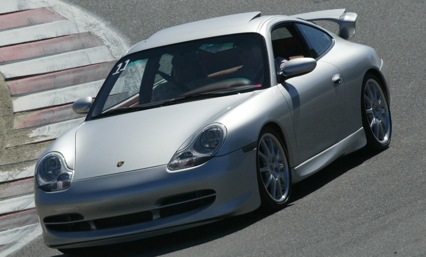
:welcome: It is located at the location as the 996 GT3. See the DIY here.
-
-0001-0001.thumb.png.17f5bb25bf8ec261a17c21e6321c8492.png)
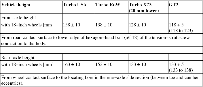
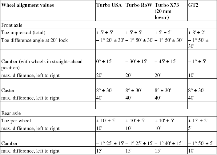
Wheel Alignment- could this be the problem?
Loren replied to TurboLove's topic in 996 TT, 996 TT S, 996 GT2
From the Service Manual (alignment specs). If your paper from the dealer does meet these - then they are wrong. Danger of injury and damage to property due to malfunctions in the PSM control range if the steering angle sensor is not calibrated or is calibrated incorrectly! - Calibrate steering angle sensor with wheels in straight−ahead position with the Porsche System Tester 2! - The steering angle sensor actual value must be checked after a suspension alignment where no changes were made to the wheel alignment values! Note: - The following values relate to the empty weight, i.e., full fuel tank, vehicle with spare wheel/collapsible wheel (not GT2) and tools, but without driver and without additional weight. - A caster adjustment is normally not necessary and is therefore not present. - The toe-difference angle value is also influenced by the vehicle height! For this reason the measured result must be evaluated accordingly! No action is ecessary in the case of small deviations from the toe−difference angle required value, as long as the value to the right and the left is almost the same!
-
How many miles on the car? That sounds like a normal usage to me. If you are really concerned by a 3rd party warranty.
-
Is the oil level sensor hard to replace? (oil level failure)
Loren replied to boosted911's topic in 996 TT, 996 TT S, 996 GT2
Model and year of your please? -
Have you tried Sunset Imports? (Porsche parts at Dealer Cost) I think around $240 from them...
-
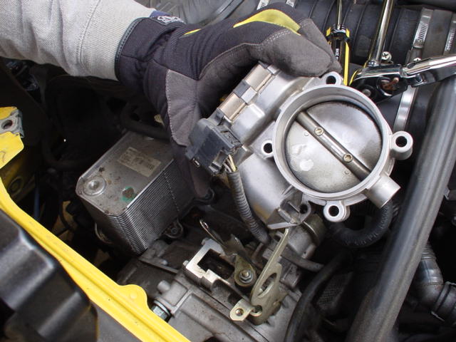
:clapping: I thought so. Both the throttle body and tube should be clean and free from dirt or grease (grease attracts dirt). I usually just put both hands around it and move it back and forth until I get one (barely) side started - then push straight on.
-
Where exactly is the Throttle Body?
Loren replied to zoomsan's topic in 996 Series (Carrera, Carrera 4, Carrera 4S, Targa)
-
Sometimes it is listed in the DME Vehicle Data - but frankly not very often. Of the half dozen or so times I've looked to see if the factory or dealer put it in - only twice has it been there.
-
The early cars through 2001 were epoxied at the factory. Who knows maybe they just wanted to save time and money - it is obvious (at least to me) that the double-stick tape side-skirts don't fit as well as the epoxied ones. There are two sets of instruction TSBs - one for the newer style and one for the early style. Look for the Aerokit Cup TSB. The epoxy can be removed - certainly not as easy as the double-stick tape but they can be removed.
-
Are you using the 12oz. bottle of Techron? I use a 16 oz. bottle (you made me look :lol: ). I also put it in - not with a full tank but when the tank is less than half full.
-
We have added and/or updated TSBs in the following categories today (31 total): Boxster (987) - 4 Cayman (987c) - 4 Carrera (997) - 8 Cayenne - 7 GT3 (997) - 4 TT (997) - 2 CGT - 2 Notable updated include: The approved oils list has been updated for all models. The 997 has updated TSBs for the X51 package and the Porsche Sport Exhaust. Several cayenne updated installation and tire/wheel TSBs. The Cayman Aerokit package TSB install is new. Battery maintenance for all newer models has been updated (987, 987c, 997, 997 GT3, 997 TT/GT2, CGT).
-
If you want a really tight fit then have a body shop epoxy glue them in place. That is the way the original factory aerokits were and they fit very tight. The reason I say body shop is that if you use the epoxy glue then they will need to be clamped/taped in place for 24 hours to cure.
-
It is not the MAF - the MAF does nothing at idle. Chancers are you have a carbon buildup around the throttle butterfly. On egas cars there is no idle control valve like the older cars - instead the throttle butterfly is opened just slightly to maintain and control the idle. If you look at the pic I posted above - that is Tariq's car and he had exactly the same problem. On the outside if you look at that throttle body it does not look to bad. But if you push the throttle butterfly open you would see carbon buildup all around the butterfly seating surfaces. Once we cleaned this off his idle was rock stable. You could try some Techron in the gas but the best short term fix is to clean the throttle body with some spray card/fuel injector cleaner (keep it off the paint). You will need to push the butterfly open with your finger to clean inside. Let it dry for a few minutes then start the car. I find a bottle of Techron every 3000 miles or really helps prevent the buildup.
-
Hello, I have the same problem, I wasn't aware of the unlock codes for the radio when I changed the battery. Becker CDR 220 type BE 4462 serial # X5023044 Thanks for your help :) Try 8967 or 8965
-
I sent you a PM...
-
Sounds like it needs the throttle body cleaned.
-
Yes, unfortunately when you go to the reviews section you may need to login again. The two systems (forums and reviews) are supposed to share the member database. But when the forum software was upgraded to a better security model the reviews software sometimes does not get passed the same information. So the bottom line is - you may have to login tot the Reviews section too.
-
A MY03 should have the new cap. You don't need to replace it unless it is leaking.
-
Try 5650 or 5648
-
From Becker to Alpine...
Loren replied to Mendrax's topic in 996 Series (Carrera, Carrera 4, Carrera 4S, Targa)
The Becker after market connector diagram is here. -
All the factory radios are Becker so someone that knows your after market radio will have to help out. Was the amp changed with the after market head? The BOSE system could have come with either the Harmon amp or the BOSE amp. The amp is in the front trunk - you will need to find the label and see what it is.
-
Welcome It would be very helpful to know the model year of your car? It would also help to us the model number on the front of your radio. Under your front hood is a sticker with some codes on it - these are option codes. You need to write those down and check them with our option lists here to see what options are on the car.
-
Clattering Followed by Misfire Code?
Loren replied to Peter986's topic in 986 Series (Boxster, Boxster S)
If it is just one cylinder then it pretty much has to be the coil, the wire, or the spark plug. -
engine compartment fan
Loren replied to alfic's topic in 996 Series (Carrera, Carrera 4, Carrera 4S, Targa)
The engine compartment purge fan rarely comes on. Mine has only come on twice -- and I live in 90 plus degree California! Here are the conditions the fan comes on at. From the service manual... "Switch-on conditions for engine compartment fan (this fan pulls air into the engine compartment) The engine compartment fan is switched on when the engine compartment temperature is > 176 degrees F or the coolant temperature is > 216 degrees F. After-running of engine compartment fan If the ignition is switched off and the engine compartment temperature is more than 140 degrees F, the DME control module remains in readiness for another 20 minutes. During this time, the engine compartment temperature is retrieved every 10 seconds. If the engine compartment temperature is > 185 degrees F , the engine compartment fan is switched on for 20 seconds. If the engine compartment temperature is still > 185 degrees F after this time, the fan remains on for a further 30 seconds." -
986.537.901.00 Left door gasket (note that this is a new number) 986.537.902.00 Right door gasket (note that this is a new number)