Welcome to RennTech.org Community, Guest
There are many great features available to you once you register at RennTech.org
You are free to view posts here, but you must log in to reply to existing posts, or to start your own new topic. Like most online communities, there are costs involved to maintain a site like this - so we encourage our members to donate. All donations go to the costs operating and maintaining this site. We prefer that guests take part in our community and we offer a lot in return to those willing to join our corner of the Porsche world. This site is 99 percent member supported (less than 1 percent comes from advertising) - so please consider an annual donation to keep this site running.
Here are some of the features available - once you register at RennTech.org
- View Classified Ads
- DIY Tutorials
- Porsche TSB Listings (limited)
- VIN Decoder
- Special Offers
-
OBD II P-Codes - Paint Codes
- Registry
- Videos System
- View Reviews
- and get rid of this welcome message
It takes just a few minutes to register, and it's FREE
Contributing Members also get these additional benefits:
(you become a Contributing Member by donating money to the operation of this site)
- No ads - advertisements are removed
- Access the Contributors Only Forum
- Contributing Members Only Downloads
- Send attachments with PMs
- All image/file storage limits are substantially increased for all Contributing Members
- Option Codes Lookup
- VIN Option Lookups (limited)


Porschelibrarian
-
Posts
278 -
Joined
-
Last visited
-
Days Won
2
Content Type
Profiles
Events
Forums
External Paint Colors
Downloads
Tutorials
Links Directory
Collections
Store
Everything posted by Porschelibrarian
-
You need the dealer version PET with complete part location and the workshop manuals so you can do some services yourself. If you need these ( and its obvious you do.. email or PM me) Here is a sample to show you a bit from the 997 workshop manuals. 997_68_17_19_Removing_and_installing_center_console.pdf
-
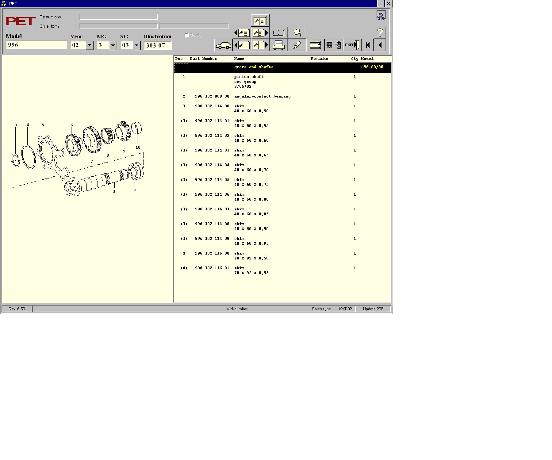
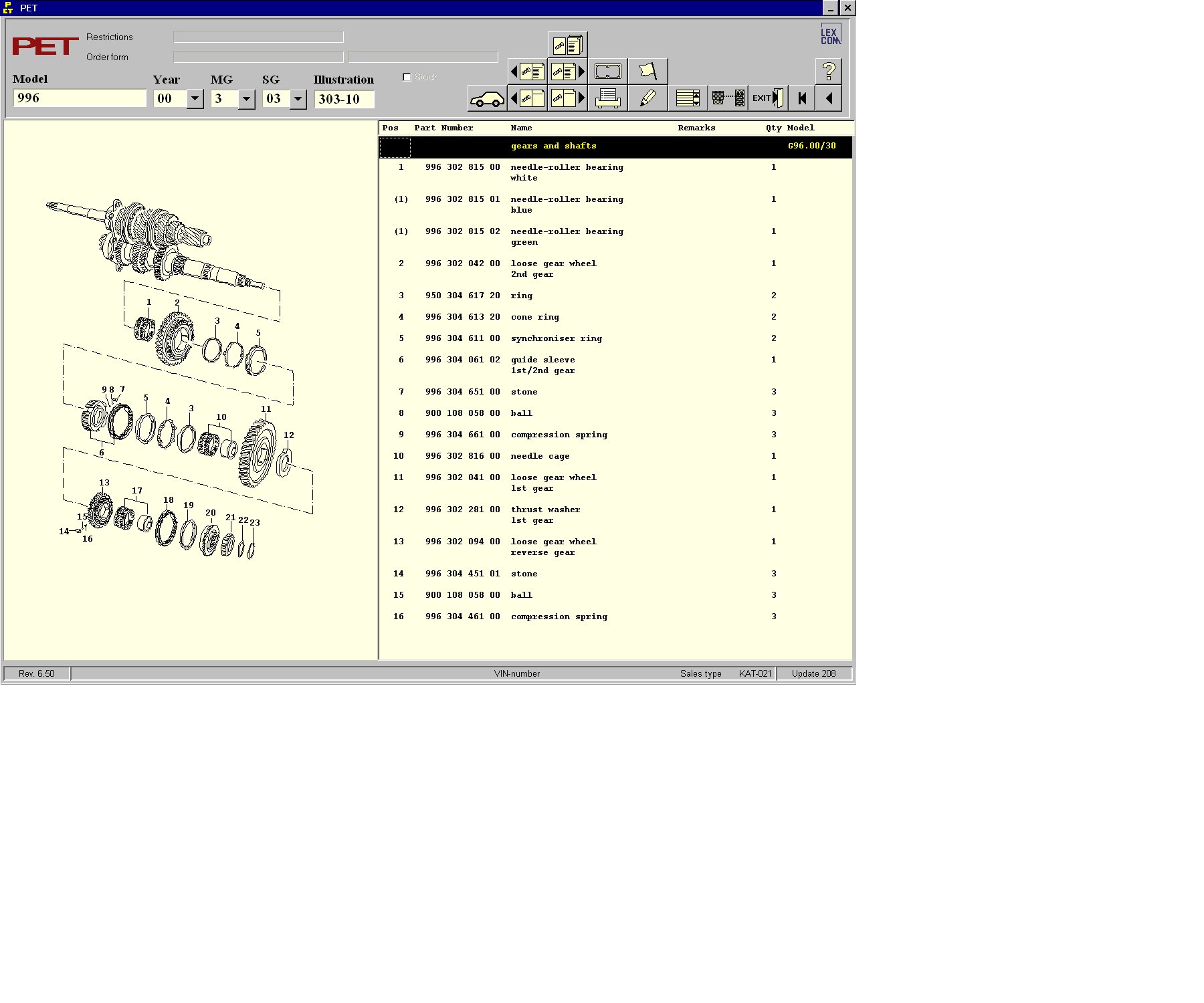
Actually they are a bit old especially for you 996 owners. The current dealer PET update 208 and later now includes the internal parts for your 6 speed transmission. If you check the online PDF crap for the 996 transmission you will see it goes from the external tranny case right to the differential without having any parts info on the gears, syncros, arms etc. The last 4 releases of the dealer PET contains the parts numbers, exploded views and more. I have uploaded but one example for you. If you want the real thing contact coke or PM me.

-
Those manuals are out of date. And they will not include your 3.6L engine. I have the updates thru 2006 and with wiring diagrams for all years from 99 thru 2005 and the TSBs thru 2006. The 996 CD/PDF they offer only covers 99 and 2000. If you look at their PET it about 4 years old. It shows update number 160 and the current version is 212 and each version comes out about once per month so 52 versions, 52 months puts it how old???? If you would like updated and as current as possible information let me know. I am constantly working to try to stay updated to keep you updated.
-
Boxster 2005 Workshop Manuals
Porschelibrarian replied to moonshadow33330's topic in 987-1 Series (Boxster, Boxster S)
You're welcome and thankyou for your positive comments. I am only trying to assist other Porsche owners ( I have an older oil cooled 911 myself) get the information we all want. -
Retail Price Search Updated (US)
Porschelibrarian replied to Loren's topic in News, Information, Rumors
I have just sent you the April Retail price list for USA. Do many members here use the Canadian retail price list? -
Retail Price Search Updated (US)
Porschelibrarian replied to Loren's topic in News, Information, Rumors
I sent you the February price lists a couple of weeks ago. I sent you the March 2003 price list last night but I got it back so I uploaded it here for you to make available to the members. 200703USDRETAIL.ZIP -
I thought I would post here and mention that Porsche has finally put the details for the 996 transmission ( gears, shafts, arms, etc) in the PET program ( as of PET update 208) and the parts are finally available thru the dealer. If you have an older PET you will notice in all years of the 996 transmission that the case and a few bolts and rings are shown and then the PET goes into the 4 wheel drive section. Now there are a few more pages including the one shown in the attachment. If you need/want the current dealer PET or more information PM or email me.
-
Boxster Maintenance Manual
Porschelibrarian replied to geoff's topic in 986 Series (Boxster, Boxster S)
I have the 986 workshop manuals, wiring diagrams, TSBs, Techniks and more and if someone needs assistance please PM or email me. The Bentley manual leaves out too much to list here. The Bentley manuals are a couple of hundred pages which is about the same amount of pages that Porsche has on any one subject such as Engine, or Exterior Body or such. Plus I have noted that most Bentley manuals have no information on Basic body work, transmission, or many other areas which are all covered completely in the Porsche workshop manuals. -
Anyone seen the PIWIS?
Porschelibrarian replied to Richard Hamilton's topic in Diagnostics, Tips and Diagnostic Tools
The PST2 or KTS 500 is not sold, supported or serviced anymore in Europe or USA. It is in the USA price list but one can't order it thru the dealers either. Loren search the price list for PST2 and you will find the price if the unit at over $7,000. -
987 desktop Chrono and manuals
Porschelibrarian replied to Porschelibrarian's topic in 987-1 Series (Boxster, Boxster S)
I now have the 2006 987 and 987C wiring diagrams so if MEMBERS need some assistance PM me.. -
I just got the 2007 997 wiring diagrams and am starting to put together the workshop manuals for the 997TT. PM me for more information...
-
PST2 units
Porschelibrarian replied to Porschelibrarian's topic in Diagnostics, Tips and Diagnostic Tools
Yes it requires a proper working Bosch interface card and since Porsche has since stopped selling them but keeps them in the price list at $3,400 it makes them hard to get. There are a few more things that are needed and a few tricks that make it difficult. -
If anyone is interested I have made a couple of PST2 units that are exactly what the dealer uses for all the 2004 and earlier models. Infact I replaced a local dealers actual PST2 with one of mine when his unit broke and Porsche and Bosch told the dealer they didn't service the units anymore. If anyone is interested let me know..
-
Retail Parts Price Search Updated (US and Canada)
Porschelibrarian replied to Loren's topic in News, Information, Rumors
You should now have the November 06 Price lists -
how easy is a heater core pull?
Porschelibrarian replied to rsfeller's topic in 986 Series (Boxster, Boxster S)
Don't just look at Bentley look at the actual Porshce workshop manuals and the PET for complete and proper instructions. The Porsche workshop manuals have over 50 pages just on the A/C Heat Ventilations system, how many does Bentley have? -
07 Turbo Wiring question while waiting for new car
Porschelibrarian replied to k950's topic in 997 TT, 997 GT2
The best I can find so far would be the 2005 997 wiring diagrams. UPDATE I now have 997TT wiring diagrams.. -
DIY 3.8 Air Cleaner change?
Porschelibrarian replied to 996TRUNDLE's topic in DIY Articles - Carrera (997-1) - Maintenance
Would changing to the 3.8 997S air cleaner box and filter provide any extra power to a 3.6L 977 ( non S)? -
2000 gt-3 cup rear drive shafts part numbers
Porschelibrarian replied to EricHart's topic in 996 GT3
I have the 2000 GT3R Parts and Technical Manuals. -
987S Alignment Settings
Porschelibrarian replied to percymon's topic in 987-1 Series (Boxster, Boxster S)
Again seems like you need the workshop manual... Here is the pages on the allignments direct from POSES! WARNING Danger of losing text-figure correspondence when printing out. For technical reasons, it can currently not be ruled out that the correspondence between text and associated figure can be lost when it is printed out, even though the display on the screen is correct. If the fault is not noticed, there is the danger that work will not be performed correctly which can cause injury and damage. → Therefore, always compare printouts with the screen display after printing them out. Correct the printouts if they are faulty so that the content of the screen display matches that on the printouts. AVERTISSEMENT Risque de perte de la correspondance texte-illustration lors de l'impression papier. Pour des raisons techniques, il ne peut pas être exclu à l'heure actuelle que, même en cas d'affichage correct à l'écran, la correspondance entre le texte et l'illustration puisse être erronée sur l'impression papier. Si l'erreur passe inaperçue, on court le risque d'exécuter certaines opérations de manière incorrecte pouvant conduire à des dommages corporels et matériels. → Comparez impérativement pour cette raison les impressions papier avec l'affichage à l'écran. Corrigez-les en cas d'erreur de manière à reproduire correctement l'affichage à l'écran. ATTENZIONE Pericolo di perdita dell'abbinamento testo-immagine nella stampa. Per motivi tecnici non è escluso che, nonostante la rappresentazione sullo schermo risulti perfetta, durante la stampa venga persa la corrispondenza fra testo e relativa immagine. Se tale difetto non viene rilevato vi è il pericolo che i lavori non siano eseguiti correttamente; ciò può avere come conseguenza lesioni e danneggiamenti. → Per questo motivo, dopo la stampa è assolutamente necessario confrontare le stampe con la rappresentazione sullo schermo. In caso di errore si prega di correggere le stampe, così da garantire la riproduzione esatta della rappresentazione sullo schermo. ADVERTENCIA Al imprimir se corre el riesgo de perder la correcta asignación de las figuras al texto. Por motivos técnicos, por el momento no se puede descartar que, aun siendo correcta la imagen que aparezca en la pantalla, al imprimir se pierda la correlación entre el texto y la figura correspondiente. Si este error pasara desapercibido, existe el riesgo de que los trabajos no se ejecuten de forma correcta y, por tanto, se produzcan daños personales y materiales. → Por ello le rogamos que tras el proceso de impresión compare siempre las copias impresas con la imagen de la pantalla. En caso de error, corrija las copias impresas de forma que se correspondan con el contenido de la imagen de la pantalla. 44 95 03 Suspension alignment, complete - as of MY 2005 - Information - Aligning vehicle at front and rear Tools Designation Type Number Explanation socket wrench insert special tool P 9730 top of page Information General procedure for wheel alignment Performing wheel alignment using an electronic wheel alignment tester. Measurement procedures should be taken from the operating instructions for the wheel alignment tester involved. In order to exclude erroneous measurements, the following preconditions must be met before alignment and the following points should be given special attention: Empty weight of vehicle according to DIN 70020, i.e. vehicle in ready-to-drive condition with full tank and including tools but without driver or additional weights. Ball-joint and wheel-bearing play in order (wheel-bearing play cannot be adjusted). Tyre pressure in accordance with regulations, fairly uniform tyre tread. Quick-clamping holder with adapter (for the measured-value pickups) correctly secured to the wheels. Receiving surfaces for the quick-clamping holder on the wheels and the adapter surfaces must be clean and flat. Always check the levelling surface on the wheels precisely in particular before fitting the quick-clamping holders. Strictly comply with maintenance intervals for measuring equipment and measuring platform. If the levelling of the measuring platform or measuring station is done in-house, levelling equipment is required. A hose level gauge is not adequate. Skilled handling of measuring equipment and measuring platform. Sliding plates with transverse motion (rotary motion) at the rear axle are advisable. Observe the Technical Literature of PAG, the manufacturer of the measuring equipment and the manufacturer of the measuring platform. Do not treat measured values as a whole, but very critically in regard to driving dynamics, high-speed strength of the tyres, tyre wear and cost/benefit effects (time required for correction of insubstantial deviations). The toe values are of decisive significance for driving dynamics and tyre wear. If the vehicle is measured front and rear, check and adjust the wheel alignment values at the rear axle first. Camber values at the front axle apply for the straight-ahead position of the wheels. Steering wheel and steering gear in centre position when toe is being adjusted. Before wheel alignment values are adjusted at front and rear axles, it is recommended that the vehicle height be checked at the DIN empty weight. Conclusions can then be drawn about wheel alignment values in the event of any suspension alignment that becomes necessary later. top of page Aligning vehicle at front and rear Vehicle height (height check) General The vehicle height at front and rear axle is not adjustable. Preliminary work For the height check, place the vehicle on a level surface or on the measuring platform (ready to drive, with a full tank and tools but without driver or additional weights). Compress (push down) vehicle at front and rear axles 2-3 times and allow it to spring back freely. Front axle Measuring height of front axle (left-hand side) From road contact surface to hexagon-head bolt of cross-member screw connection to the body. Nominal value for front and rear axles → 441000 Adjustment values for suspension alignment. Rear axle Measuring the height of the rear axle (right-hand side) Measure from wheel contact area up to lower edge of diagonal brace (at control arm fastening point). Wheel alignment WARNING Risk of accident due to incorrect functioning of steering angle sensor if it is uncalibrated or incorrectly calibrated. There is a risk of accidents causing physical damage to persons or objects in the PSM testing area. → After working on wheel suspension parts, when replacing the steering-angle sensor and after changing the wheel alignment values, calibrate the steering angle sensor with the front wheels in straight-ahead position using the PIWIS tester. → Check the actual value of the steering angle sensor after a suspension alignment where no changes were made to the wheel alignment values. Notes Only check or adjust wheel-alignment values when prescribed preconditions are met. → 449503 Suspension alignment complete - chapter on "Information" If the vehicle is measured front and rear, check and adjust the rear axle first. After adjustment, tighten the appropriate threaded connections with the prescribed tightening torque. See tables in Repair Group 40 → 401000 Tightening torques for front axle and Repair Group 42 → 421000 Tightening torques for rear axle. The steering-angle sensor must be calibrated if the previous wheel alignment values (on rear and/or front axle) were changed! Rear axle Preliminary work Prepare vehicle for checking and/or adjustment of wheel alignment values. Place front wheels on rotary table and rear wheels on rotary / sliding plates. Compress vehicle at front and rear axles by approximately 25 mm 2-3 times and allow it to spring back freely. Adjusting camber Toe and camber eccentrics After loosening the lock nut, turn eccentric -B- appropriately. Note Due to the restricted space, to tighten the lock nut of the left camber eccentric, use a 3/8 inch torque wrench (covering the range of 100 Nm (74 ftlb.)) together with a 18 mm socket-wrench insert. 3/8 inch torque wrenches and 3/8 inch socket-wrench inserts have a smaller height than tools of the same size in a 1/2 inch version. Tighten lock nut from camber eccentric to the prescribed tightening torque → 421000 Tightening torques for rear axle. To do this, use a 3/8 inch torque wrench (covering the range of 100 Nm (74 ftlb.)) together with an 18 mm socket-wrench insert on the left side. Adjusting toe Toe and camber eccentrics After loosening the lock nut, turn eccentric -A- appropriately. After adjusting, tighten the lock nut of the toe eccentric to the prescribed tightening torque → 421000 Tightening torques for rear axle. Front axle Adjusting camber Adjusting camber The camber is adjusted by moving the spring strut transversely. For this purpose, undo the three fastening nuts on the spring-strut mount and, to move the spring strut, remove the covering cap on the piston rod. Adjusting caster The caster is not adjustable on standard vehicles. Adjusting toe Preliminary work: Check whether the steering wheel is displaced with respect to the steering gear. To do this, centre the steering gear as described below. Turn wheels to the straight-ahead position. Steering in centre position Then re-adjust the front wheel alignment, if necessary, until bolt -2- in driver -1- and the lug on the steering gear housing -4- line up. Steering in centre position No. 3 is the desired breaking point for bolts in new steering gears. The (new) bolt -2- is inserted into driver -1- and lies with its underside in lug -4- . This locks the steering gear in the centre position. After installation of a new steering gear, the lower part of the bolt is sheared off (at desired breaking point -3- ) by turning the steering wheel. The upper part of the bolt -2- remains in the driver. Mark for the centre steering position If necessary, reposition the steering wheel. When doing this, seek the best position. WARNING A triggering of the airbag (malfunction in the airbag system) caused by improper work on airbag components cannot be ruled out. In the case of such a malfunction, an unsuitable steering wheel holder could cause injury or damage. → Use only steering wheel holders that do not project into the area of the airbag unit! → Observe safety regulations when working with airbag vehicles (see in Repair Group 69)! Steering wheel holder Clamp steering wheel in centre position with steering wheel holder -A- . Use only steering wheel holders that do not project into the area of the airbag unit -B- ! If necessary, shorten the guiding rod of the steering wheel holder at top -Arrow- . Adjusting toe Loosen tie rod lock nut(s) -2- . When loosening and tightening the tie rod lock nut(s) counter on the square of the tie rod -3- , with an open-ended wrench. Then adjust the toe on the hexagon -1- of the tie rod(s). Then tighten the tie rod lock nut(s) -2- to the prescribed tightening torque. Loosening and tightening tie rod lock nuts Use special tool (socket wrench insert) P 9730 -A- together with a torque wrench -B- to loosen and tighten the tie rod lock nut(s). The tightening torque of 50 Nm (37 ftlb.) for the tie rod lock nut(s) corresponds to a value of approx. 32.5 Nm (24 ftlb.) when using a socket wrench insert P 9730. Toe-difference angle The toe-difference angle is not adjustable. The steering angle sensor must be calibrated if the previous wheel alignment values (on rear and/or front axle) were changed. -
Brake Fluid Change and Clutch Fluid
Porschelibrarian replied to White987S's topic in 987-1 Series (Boxster, Boxster S)
Yes. Yes. No. THANKS, Loren! That's what I thought. I had a dealership (Westmont, IL Porsche) tell me today that they were seperate systems. It is so frustrating when the dealership tells you wrong info...or when you know more than they do! If you need the workshop manual for the 987 ( The new revised version has grown to about 3,500 pages from the "Basic Workshop" manuals I had last year ) let me know. -
I have a Porsche 987 CD that has a few Computer and cel phone applications related to the 987. Here is a link to the SPORT CRONO for your PC... http://rapidshare.de/files/31565383/987Chrono.zip There are screen savers, ringtones, icons, and more on the CD and I do have the 987/987C workshop manuals too...
-
I just got some new information and have put together the 987/987C ( Boxster and Cayman ) workshop manuals with the CDs that Porsche has sent out to the dealers this year. The manuals are aprox 3,500 pages and cover the 987 987S and 987C. I will try to attach one page for you to see 1001TW_0.htm
-
PST2 User Manual
Porschelibrarian replied to Nick_USA's topic in Diagnostics, Tips and Diagnostic Tools
The ODII manuals have a very brief section about how and what the PST2 will do. -
I would suggest you look thru the 993 OBDII manual. It should get you on the right track. The OBDII manuals are written for use with a PST2 but you should be able to adjust the info to the reader you are using.
-
You were the same guy that contacted me 2 years ago about being so busy then too. Here is a quote from your email.."I don´t whant to spend hours >scanning and working on the sheets if I can get them from you. > >Regards, >Pierre " I can help you replace everything and more as well as bring all the material up to date.