Welcome to RennTech.org Community, Guest
There are many great features available to you once you register at RennTech.org
You are free to view posts here, but you must log in to reply to existing posts, or to start your own new topic. Like most online communities, there are costs involved to maintain a site like this - so we encourage our members to subscribe or donate. All subscriptions and donations go to the costs operating and maintaining this site. We prefer that guests take part in our community and we offer a lot in return to those willing to join our corner of the Porsche world. This site is 99 percent member supported (less than 1 percent comes from advertising) - so please consider an annual subscription or donation to keep this site running.
Here are some of the features available - once you subscribe RennTech.org
- View Classified Ads
- DIY Tutorials
- Porsche TSB Listings (limited)
- VIN Decoder
- Special Offers
- Paint Codes
- Registry
- Videos System
- View Reviews
- and get rid of this welcome message
It takes just a few minutes to register, and it's quality Porsche information at a low cost.
Contributing Members also get these additional benefits:
(you become a Contributing Member by subscribing or donating money to the operation of this site)
- No ads - advertisements are removed
- Access the Contributors Only Forum
- Contributing Members Only Downloads
- Send attachments with PMs
- All image/file storage limits are substantially increased for all Contributing Members
- Option Codes Lookup
- VIN Option Lookups (limited)


1schoir
-
Posts
2,739 -
Joined
-
Last visited
-
Days Won
9
Content Type
Profiles
Events
Forums
External Paint Colors
Downloads
Tutorials
Links Directory
Collections
Classifieds
Store
Everything posted by 1schoir
-
Steering wheels shakes when braking
1schoir replied to gregthiara's topic in 996 TT, 996 TT S, 996 GT2
If you are getting "pulsing" through the brake pedal when you lightly apply the brakes, and your car shudders under heavy braking, there are two main causes: either lateral runout of the rotor or a variation on the thickness of the rotor on the surface that is subjected to friction from the brake pads. Even if the rotors are relatively new, you can still experience runout if the lugs were improperly torqued (over-torqued or unevenly torqued), or if there is some corrosion build-up between the hub and the rotor. I am assuming you have checked to make sure that your lug nuts are not loose. Even if the rotors are relatively new, I would check their thickness with a caliper to make sure they are within spec in case the ones that were installed are not up to par. Checking for lateral runout requires a more expensive tool. Unless you are getting noise coming from the front wheels under hard cornering, the bearings are not the prime suspect. Regards, Maurice. -
Convertible top tension cable
1schoir replied to mpikounis's topic in 996 Series Part Number Requests
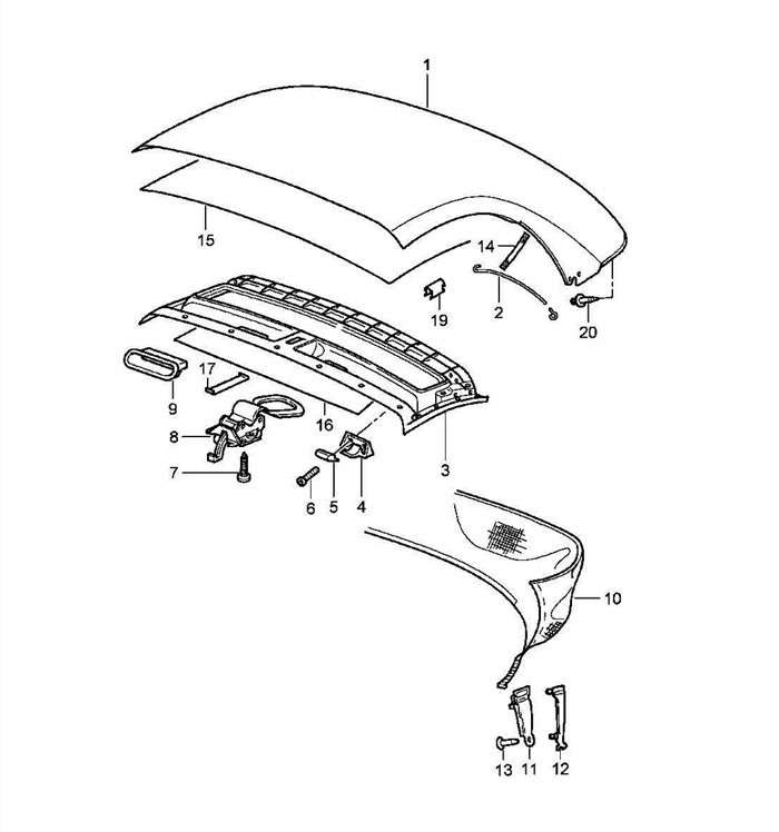
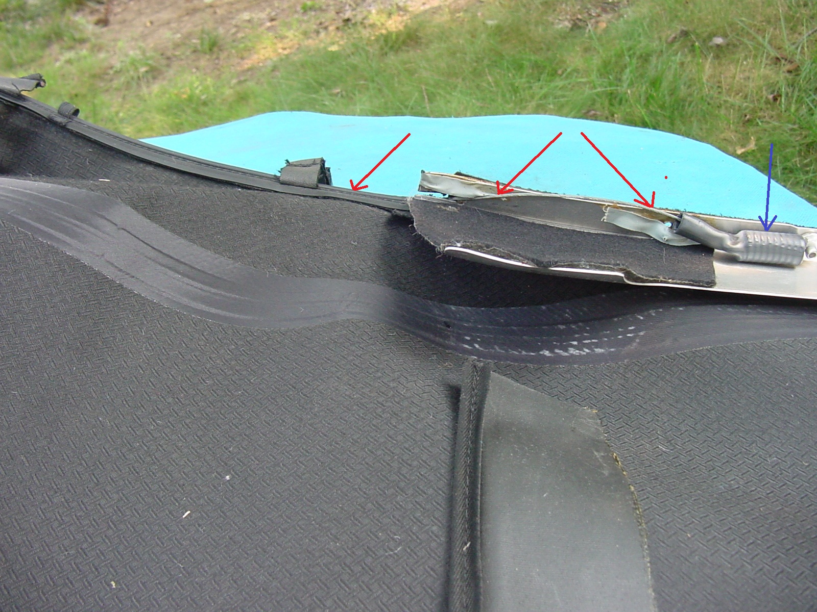
PE: Although the cable appears to be short, I believe that is only because of the illustration, which is not to scale. I have replaced the same cable in a Boxster and the illustration is the same (cable is item #2). Although it looks short, the cable (in a Boxster) runs from under the B-Pillar frame of the convertible top, where it terminates in an eyelet, to the aluminum shoulder plates on the sides, near the front of the top, where it is attached to those plates with a spring, as the OP described. Here is the same diagram from the Boxster: For reference, here is a photo of what the cable and shoulder plate look like (again in a Boxster), showing where the cable attaches to the spring at the shoulder plate: (Red arrows are the cable and, towards the rear, it runs inside a vinyl sheath or piping, blue arrow points to the spring under its rubber sheath) Regards, Maurice.
-
Convertible top tension cable
1schoir replied to mpikounis's topic in 996 Series Part Number Requests
I believe this is the part you are looking for (one for the right side, one for the left side): It's item # 7 in the diagram...Porsche part number 996.561.931.01 Double check with your parts supplier before ordering to make sure. Regards, Maurice.
-
Darrin: No need to disassemble any door trim for any of these adjustments-- either height or angle. The only parts you have to remove are the four rubber plugs on the underside of the door shell: the two OUTBOARD ones for adjusting the height, and the two INBOARD ones for adjusting the angle. When you remove the inboard plugs, you will have access to the nut which is under each of the two legs of the window regulator: one at the front, and one at the rear. Once you loosen those nuts, if you move the leg outboard at its bottom, that will result in moving the window glass angle slightly inboard at the top and vice versa. This is a photo of the REAR leg of the window regulator in the driver's side door on a U.S. car (left side door). (click on it to enlarge for detail). The red arrows are pointing to the E6 torx head screw and to the outboard plug, and show the angle at which the driver must be inserted to get to that screw (with the window in down position). The green circle shows the top side of the stud onto which the nut is threaded from the underside. That is the nut to loosen for the adjustment to the angle of the window. The yellow arrow points to where the edge of the inboard plug in located under the base of that leg. Regards, Maurice.
-
Conv Roof Interior elastic band with hook
1schoir replied to ga9374460's topic in 986 Series (Boxster, Boxster S)
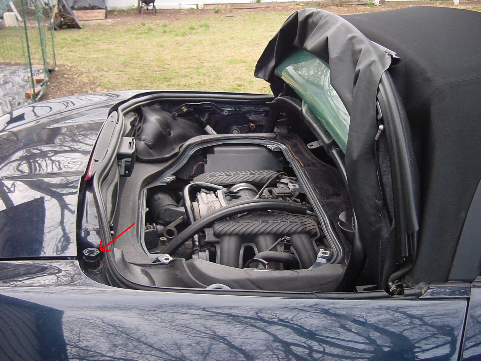
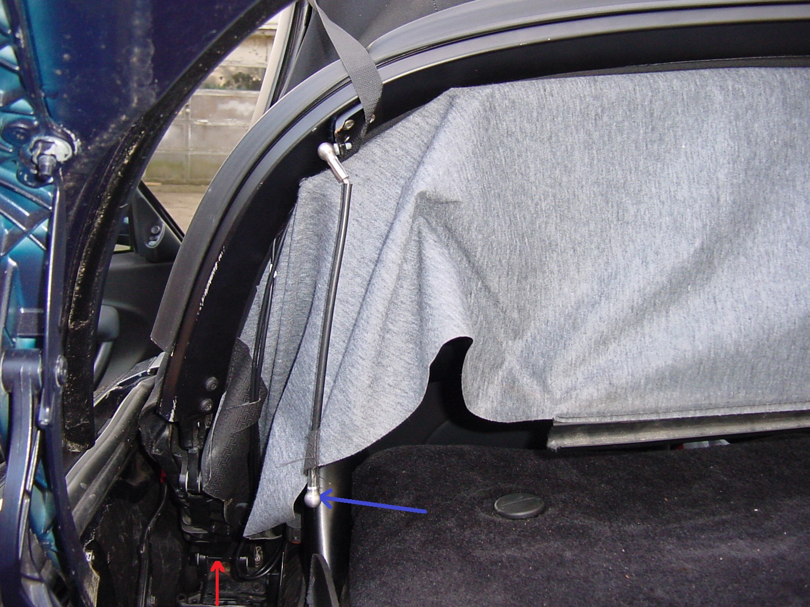
Joel: Correct, the clamshell is the sort of half-moon shaped metal cover that ends up over the convertible top when the top is in the completely open final position. Here is a photo of the top in the service position, but in this photo note that the clamshell has been completely removed (for some other work on the engine) (also disregard the red arrow). In the normal service position, the clamshell will then be in the rearmost, 45 degree position. That is the position that the top should be in when you have pulled up the rear main bow (after you disconnect the tension ropes and after the front of the convertible top edge is operated so that it is about 8 to 12 inches from the top of the windshield frame). You don't have to disconnect any of the pushrods, only the metal cups at the bottom end of the tension ropes. Here is a photo of one corner of the convertible top and clamshell in the service position. The blue arrow is pointing to the bottom metal ball cup at the end of the tension rope on the left side, after it has been disconnected and the rear main bow has been pulled up into the service position. The red arrow is again showing the little horizontal rod to which the hook gets connected. Also, this photo is from a Boxster that came without the roof liner ('97), so although your hook does not show up there, that's the rod that it gets hooked under. Don't worry about the questions. We've all been there. Regards, Maurice.
-
Conv Roof Interior elastic band with hook
1schoir replied to ga9374460's topic in 986 Series (Boxster, Boxster S)
Joel: The service position is with the clamshell as far back as it will go, at a 45 degree angle...then you unhook the black plastic horizontal rod that is clipped onto the rear wall of the convertible top well, then you unsnap the two tension ropes at their lower points (at the rear and to each side of the carpeted cover on top of the engine cover), and then you can pull up the rear main bow of the convertible top frame (where you will feel some resistance). The procedure is covered in your owner's manual, if you have one. Otherwise, you can download a copy of a manual from "Documents Menu" tab at the top of this page by selecting "Owners Manuals" from the pull-down menu. In that position, you will see the little metal rod onto which the hook attaches, and you will see how it looks on your driver's side, which should still be attached on that side. Regards, Maurice. -
Conv Roof Interior elastic band with hook
1schoir replied to ga9374460's topic in 986 Series (Boxster, Boxster S)
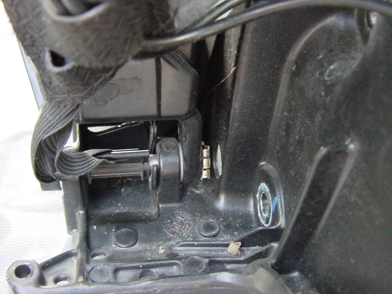
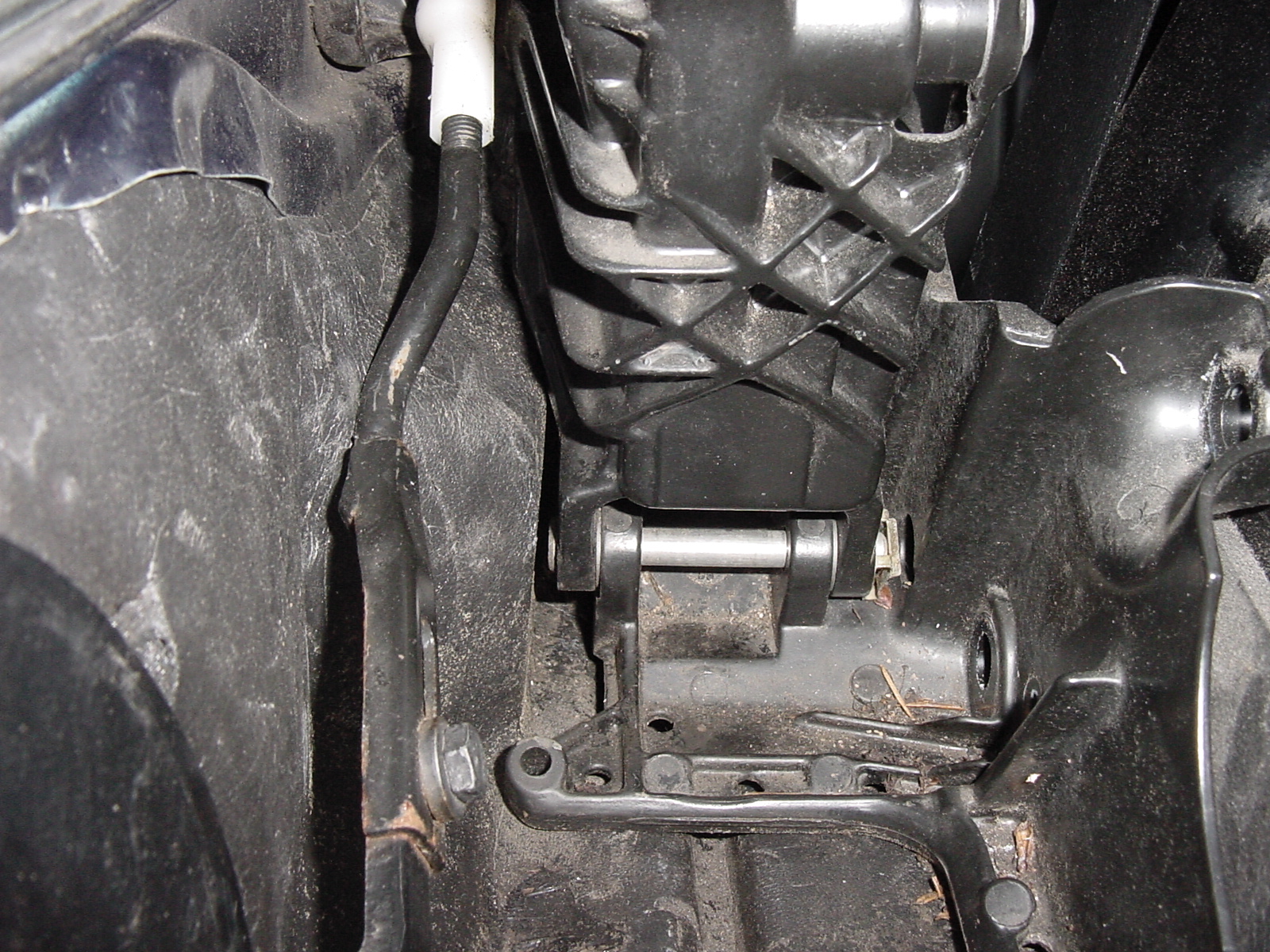
Joel: You have to look from the other side of the view that your photo shows. To get oriented, put the top in the service position and stand behind the car, looking forward towards the base of the B-Pillar so that you can understand what you are trying to hook onto. Here are two photos of the driver's side little metal bar under the B-Pillar that the hook is supposed to hook around. . . In the second photo, both that hook and the wider hook from the vinyl apron have been removed and you can see the pushrod all the way on the left, attached to the steel ball at the base of the B-Pillar. Hope that clears it up, otherwise I can look for more photos. Regards, Maurice.
-
Conv Roof Interior elastic band with hook
1schoir replied to ga9374460's topic in 986 Series (Boxster, Boxster S)
Joel: No need to remove anything to hook it back in. Just make sure that you route it (the hook) from where it is attached at the rear tail of the liner to the base of the front of the B-pillar, then hook it underneath so that the hook comes up, around and behind the horizontal metal rod on the INBOARD side of the other, wider clip. Before you hook it in there, make sure that the elastic strap onto which the hook is attached has not lost all of its elastic, otherwise it will probably fall off again. If it has lost all of its elastic properties, you can cut out and replace that piece of elastic band with material you can get from a craft or millinery supply store. If you don't want to go to those lengths, you might be able to just shorten that band slightly by sewing the band onto itself for a 1/2 inch, etc., or just tying a knot in it. If you take the shortcut, make sure you observe the tension on that hook while the top goes through a few cycles so that it doesn't end up too short and then rip off its strap. Regards, Maurice. -
Darrin: Although I think that there is a mechanism out of adjustment inside that small section of the convertible top frame, if you want to get the window to go up a little further (thereby at least stopping the rain and reducing the wind noise), there is a relatively easy adjustment that can be done WITHOUT removing the door panel. (This is from a 986, but I'm reasonably sure that it's the same mechanism for your car). There are four rubber plugs located on the door bottom surface. To adjust the height of where the window stops, you must first remove (pop out) the two OUTBOARD plugs. Then, reach through the holes with an E6 Torx driver socket and turn the screws, one at a time until you achieve the desired adjustment. To keep track of how much you have adjusted, mark the top of the window with masking tape or, preferably with a wax pencil, tracing the top surface of the window where it meets the seal at the top. There is a little more than 1/2 inch of adjustment through this method. Note that the Torx adjustment screws are on an angle, raked back at an angle similar to the rear edge of the door. Here's a photo that should help you get oriented: Note: The green arrow shows the outboard plug that must be removed, at the forward part of the driver's door. The red arrow shows the very edge of the inboard plug (which should only be used to adjust the inboard/outbard angle of the window by means of loosening and then shifting each leg of the window regulator). The outboard ones are the ones you want to remove so that you can access the Torx screws for your particular adjustment. The yellow arrow shows the head of one the Torx screws that you are looking for, in this photo the one on the forward leg of the window regulator frame. You have to do the same to the one on the rear leg, but again it's located above the OUTBOARD plug. With a little patience, you should be able to minimize the wind noise and water leak. If your dealer finds the adjustment to straighten out the fitment of the convertible top frame, please let us know. Regards, Maurice.
-
Conv Roof Interior elastic band with hook
1schoir replied to ga9374460's topic in 986 Series (Boxster, Boxster S)
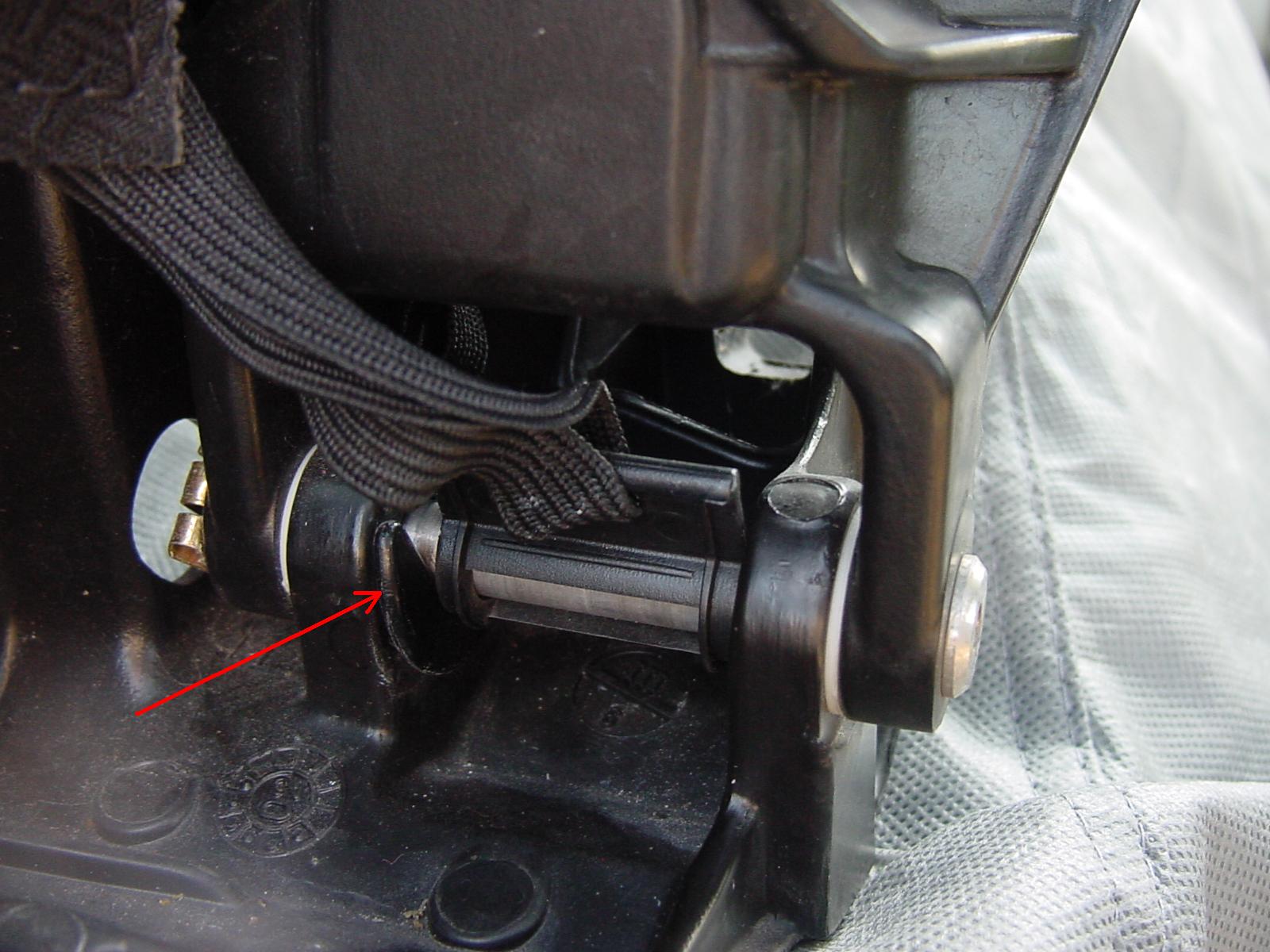
Joel: Found the pic. Here it is (click on the photo to enlarge for a better view): Note that this photo is of the passenger side B-Pillar base, so make sure you position your hook INBOARD of the wider plastic hook that is attached to the elastic from the front edge of the rear vinyl apron. Regards, Maurice.
-
Conv Roof Interior elastic band with hook
1schoir replied to ga9374460's topic in 986 Series (Boxster, Boxster S)
Joel: That plastic hook on its elastic band provides tension for the very rear of one side of the convertible top liner that came on Boxsters after MY 99. The hook is supposed to fit under and around the silver metal horizontal bar that is at the base of the B-Pillar on each side. I'll try to dig up a photo of that part in place and post it here. Regards, Maurice. -
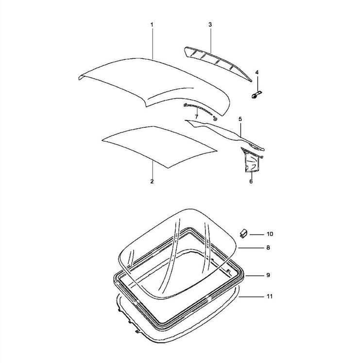
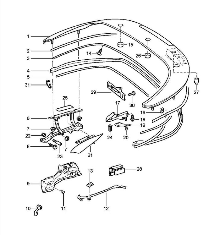
David: That is your left side "cabriolet cover flap", part #21 in the following parts diagram: Regards, Maurice.
-
Looks VERY EXCELLENT! Quite a dramatic difference for a relatively straightforward mod. Now that you have started modding, what's next? Regards, Maurice.
-
and congratulations on your new acquisition! Here is the ultimate battery thread: http://www.renntech.org/forums/index.php/topic/2950-battery/ The thread is both informative and entertaining, IMO. Regards, Maurice.
-
Convertible Top Closing Problem
1schoir replied to jinijazz's topic in 987-1 Boxster Convertible Top Issues and Solutions
We forgive you! LOL!!! Here is a write-up on the possible causes, known as "When the Top Edge Doesn't Fall into the Guide Channels": http://sites.google.com/site/mikefocke2/convertibletopedgedoesnotfallintoguidech Note that the write-up concentrates on this problem as it occurs on 986's, but most of it applies to 987's. Also note that the "finger-spring" on 987's is slightly different in shape, but the same advice applies. In your case, I would check the "looped string" first and then check the velcro straps. Keep us posted. Regards, Maurice. -
Alternator parts
1schoir replied to Scouser's topic in 996 Series (Carrera, Carrera 4, Carrera 4S, Targa)
Berny: Very satisfying! Regards, Maurice. -
Custom exhaust - on the cheap!
1schoir replied to Dr.Strangepork's topic in 986 Series (Boxster, Boxster S)
Dr.: Looks really nice and it looks like you shed some weight as well! If you install those CC inserts and the drone disappears, this would appeal to a lot of members. Regards, Maurice. -
Question on AOS install.Help!
1schoir replied to BoxSinit's topic in 986 Series (Boxster, Boxster S)
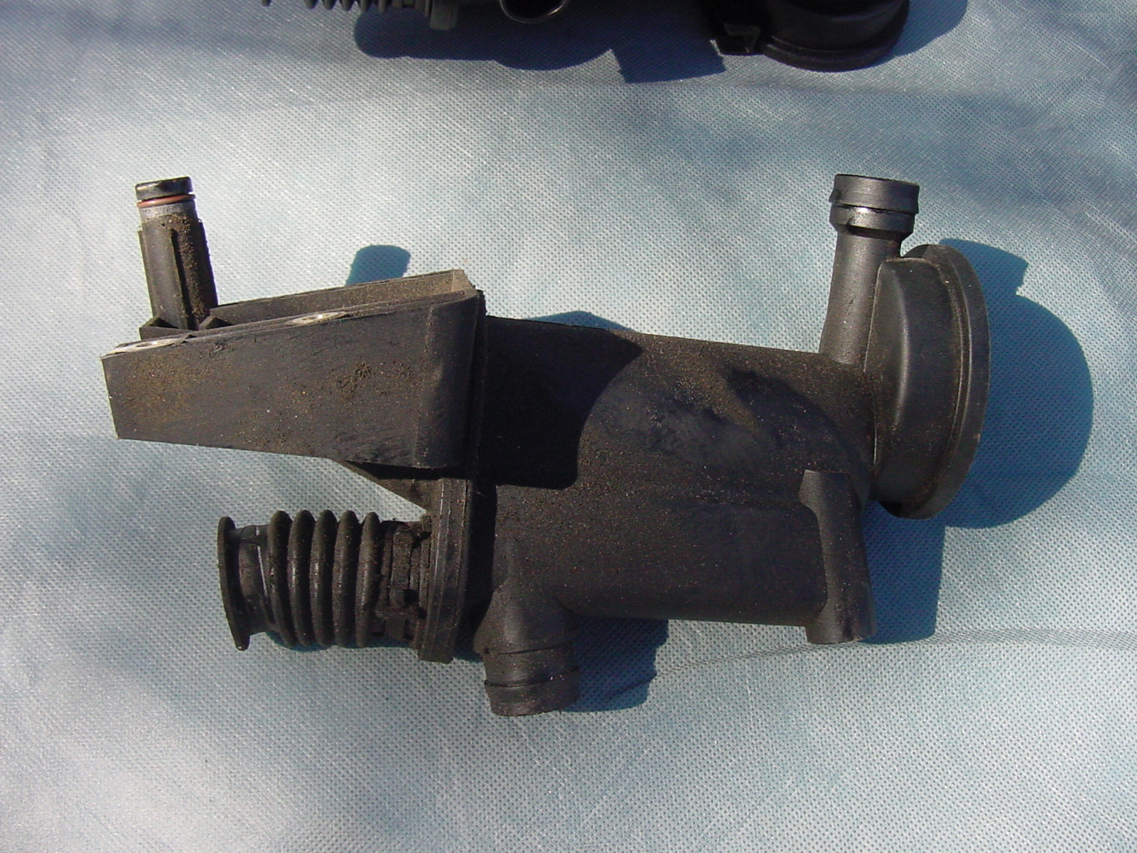
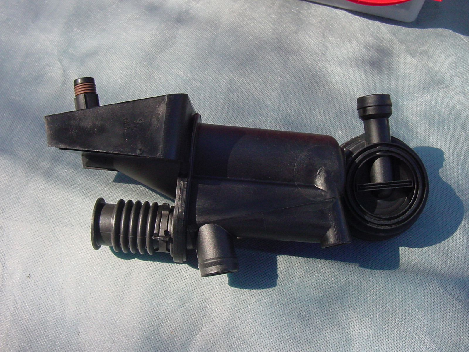
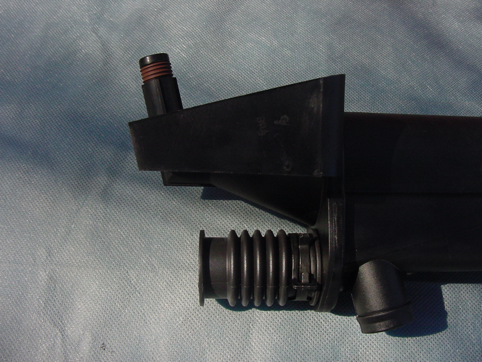
Note that there is a difference in the width/design of the seal in question depending on the version of the AOS. These photos can help to clarify the difference (click on the first one to blow it up): Old Version Newer Version Newer Version Closeup Regards, Maurice.
-
You can get some additional information from the ECU which you might find useful in making your decision. There is data available which tells you the total number of hours that the engine has been in operation, usually listed as "operating hours counter". Then, following the number of "overrevs" of each type (i.e., Type 1 and Type 2, in the case of a 996TT 6750 to 7250 and 7250 and up, respectively ) there will be a figure followed by a small "h". The figure that is followed by a small "h" will tell you at what operating hour the LAST overrev of that type occurred. If you compare the figure for the Type 2 overrev with the total operating hours, you will learn how recently (in terms of operating hours) that happened. The operating hours can also help you determine whether the mileage reflected on the odometer is "real". You can take the mileage of 9700 and divide it by the number of hours that the engine has been in operation. That will give you an AVERAGE miles per hour figure. If the figure is far outside the range of 30 to 50 mph, I would have some reservations. If it falls squarely in that range, it might increase your confidence factor. Let us know which way you go...and don't forget to post photos when you finally get one! Regards, Maurice.
-
Broken Top pushrod ball joint cap, AGAIN
1schoir replied to tomie_1's topic in 987-1 Series (Boxster, Boxster S)
+1... If the mechanism is in good shape you should be able to open and close it by moving it with your pinky. If it's binding anywhere, moving it back and forth with both front pushrods disconnected will reveal where the problem is. If it's not binding, you could adjust the length of the front pushrods after determining whether they are correctly set at their current length. If you have no idea as to what the correct length of the pushrods is, you could put the top in the completely closed position with the front pushrods' plastic ball cups pressed on to the B-Pillar steel balls, BUT with the 10mm nut which holds the two sections of each pushrod together slightly loosened. That will get the top to the closed position and the pushrods at the approximate correct overall length. You can then tighten the 10mm nut so that the pushrods' length is locked in position. Be aware that the overall length of the front pushrods affects how the horizontal leading edge of the canvas top lines up with each side of the top horizontal edge of the windshield frame and that the resulting adjustment is NOT a strictly linear progression. At some point, the front edge of the top on the side of the pushrod that is being adjusted will pull back (rather than overshoot) that edge. Before you make any adjustment, be sure to mark the front pushrods' overall length at the point where the two sections of a pushrod connect so that you have a starting point. If you have to make a finer adjustment, you can just screw (or unscrew) the plastic ball cup one turn at a time. The 10mm bolt will give you a gross adjustment. Regards, Maurice. -
Byron: Excellent work finding the cause, even if it was a PITA. You might want to reconsider the lightweight flywheel option. FWIW, at Sebring two weekends ago, one of the cars campaigned by a racing group from New York broke a crankshaft on a 996 engine that was running a lightweight flywheel. Charles Navarro of LN Engineering, as well as others, have long cautioned against the use of lightweight flywheel unless the engine is disassembled and the crankshaft and flywheel are balanced as one unit. Regards, Maurice.
-
Zaktoo: Looks like an excellent result. "After" photos of the painted bumperettes on the car would be great to see! As far as longevity, the weak point may turn out to be the lack of flex agent in the color coat and in the clear coat. That would require you to have to use a spray gun set up. Since you have them painted now, you won't get any more of that sun and ozone damage on the now-painted bumperettes. If there is a next time, it will be that much easier to prep and redo. Thanks for posting the DIY! Regards, Maurice.
-
Spark Plug Tube grease for $40?
1schoir replied to westladog's topic in 986 Series (Boxster, Boxster S)
+1! . . IMO, changing the oil without changing the filter is like taking a shower and putting on dirty socks! Regards, Maurice. -
Question on AOS install.Help!
1schoir replied to BoxSinit's topic in 986 Series (Boxster, Boxster S)
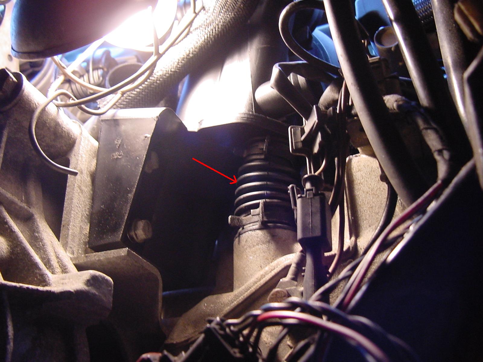
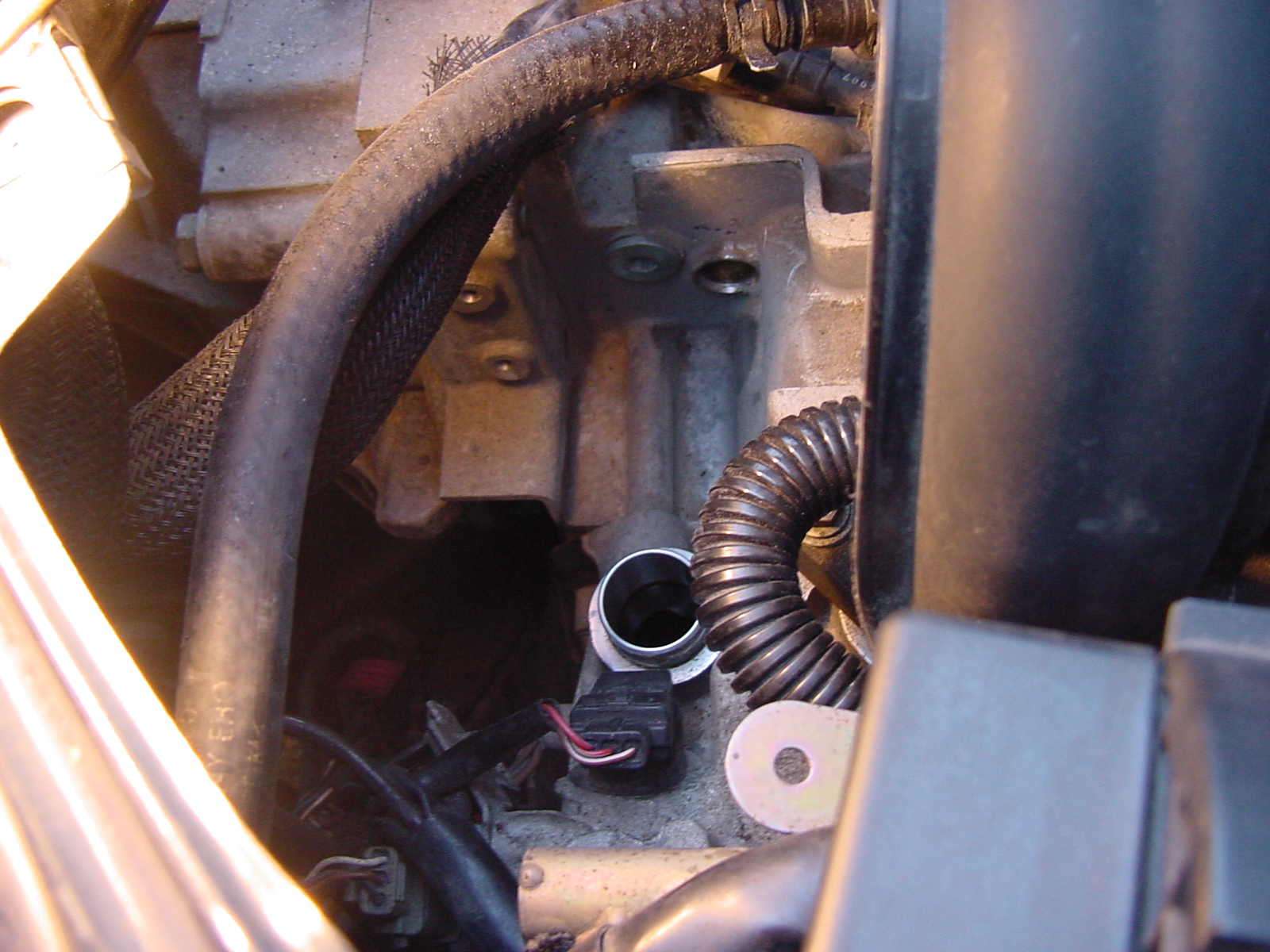
+1 for Harry's recommendation that you remove and clean up the tubes and the throttle body. As for lubricating that O-ring, Porsche sells a "special" lubricant in a tube called Syntheso-Glub or something, but any good rubber grease will do. If you are concerned about longevity, get a grease that does not attack rubber. Are you sure it's the O-ring that you see protruding outward? There are two raised bosses on the engine case at the point where the two 10mm bolts are inserted into the block and that may be what you are seeing. Here are two photos that show you the raised bosses, with and without the AOS installed. Be sure to check that the bellows (red arrow) is seated properly, as that is usually the area that gives everyone some headaches in the install. Looking down from the top of the engine, with the AOS removed. You can see the two bosses (just under the two hoses) and the larger tube/hole onto which the bellows gets installed. Looking from underneath the right rear wheel well, you can see that the face of the AOS housing is not completely flush with the engine block because of the two raised bosses. Good view of the bellows and how it should be seated squarely and flush down onto its tube. (Note that the lower of the two 10mm bolts has not been tightened yet in this photo). Regards, Maurice.
-
Spark Plug Tube grease for $40?
1schoir replied to westladog's topic in 986 Series (Boxster, Boxster S)
What is ..... 76X14 flute socket for oil cannister. That is a cup-like "socket" which fits over the bottom of the oil filter cartridge canister for removal of the oil filter. Regards, Maurice.