Welcome to RennTech.org Community, Guest
There are many great features available to you once you register at RennTech.org
You are free to view posts here, but you must log in to reply to existing posts, or to start your own new topic. Like most online communities, there are costs involved to maintain a site like this - so we encourage our members to subscribe or donate. All subscriptions and donations go to the costs operating and maintaining this site. We prefer that guests take part in our community and we offer a lot in return to those willing to join our corner of the Porsche world. This site is 99 percent member supported (less than 1 percent comes from advertising) - so please consider an annual subscription or donation to keep this site running.
Here are some of the features available - once you subscribe RennTech.org
- View Classified Ads
- DIY Tutorials
- Porsche TSB Listings (limited)
- VIN Decoder
- Special Offers
- Paint Codes
- Registry
- Videos System
- View Reviews
- and get rid of this welcome message
It takes just a few minutes to register, and it's quality Porsche information at a low cost.
Contributing Members also get these additional benefits:
(you become a Contributing Member by subscribing or donating money to the operation of this site)
- No ads - advertisements are removed
- Access the Contributors Only Forum
- Contributing Members Only Downloads
- Send attachments with PMs
- All image/file storage limits are substantially increased for all Contributing Members
- Option Codes Lookup
- VIN Option Lookups (limited)


darrinsmith
-
Posts
179 -
Joined
-
Last visited
-
Days Won
1
Content Type
Profiles
Events
Forums
External Paint Colors
Downloads
Tutorials
Links Directory
Collections
Classifieds
Store
Everything posted by darrinsmith
-
Thanks Could you elaborate on how I might do that (isolate each module). Can I just pull a fuse? or do you mean pull out the control panel (with the temp displays) and disconnect them one at a time? Thanks DS UPDATE I reset the gateway by pulling the fuse, waiting 10 s and putting it back in, and was able to communicate with it via durametric. It is not showing any errors at all. The air cond module is still showing multiple flap servo errors (same as in the second section of my post) but is no longer showing the 1336 and 1299 errors. I also checked the voltage across my battery (at the jump terminals in the engine bay). With the car turned off it's showing 12.47V, so that seems ok. The battery is about 3-4 years old but when I replaced it last time I put in a really expensive Varta AGM battery, which should last a bit longer than a lead acid job. Thanks DS
-
Hello again. My air cond has gone mad. It is only blowing cold air (regardless of the temp setting) on the right side of the front (driver's side here). As a consequence it blows really hot air through the left in an attempt to get the cabin temp correct, which annoys my wife no end! Curiously this all started about the time I changed the cabin air filter (it was totally blocked solid). I'm getting heaps of errors from durametric. If I clear the error codes a few remain but they all generally come back after a day or two. The rear air cond is working fine (depsite the errors that seem to suggest otherwise). Also note my Kessy is stuffed (see my other post) but it's been stuffed since before this all started happening. (I assume this is the error 1336?). I assume there's a hot/cold left/right servo that's gone and this is causing on-flowing problems. Also I'm note sure what the Gateway error is (1299). There are no error codes on the gateway when I scan it. Can anyone assist with a diagnostic procedure? The durametric transcript is below. Vehicle is a 2003 turbo with rear air cond option (obviously!). Thanks! DS Air Conditioning Module Identification Part Number 11Diagnoss Number Current Fault Codes 711Servo motor for footwell flap left 713 Servo motor for central vents left 1810 Drive motor for temperature valve right 1596 Servo motor for fresh-air/air circulation flap 712 Servo motor for footwell flap right 710 Servo motor for defrost flap 1336 CAN comfort OFF No signal/communication 1299 Gateway Please read out fault memory 2599 Temperature flap servo motor rear left 2597 Rear left air vent on tunnel 362 Servo motor for volume air flow flap rear left 2600 Temperature flap servo motor rear right 363 Servo motor for volume air flow flap rear right After clearing the faults the following remain... 711 Servo motor for footwell flap left 1810 Drive motor for temperature valve right 1596 Servo motor for fresh-air/air circulation flap 2599 Temperature flap servo motor rear left 362 Servo motor for volume air flow flap rear left 363 Servo motor for volume air flow flap rear right
-
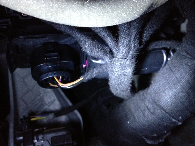
Hello After reading clarksongli's excellent tutorial on fixing a broken Kessy, I was finally motivated to fix mine. However I can only find information relating to LHD cars. On a RHD car, the Kessy is located on the firewall side (not the centre) of the vehicle. Porsche have simply moved the entire dash assembly to the right of the car, and not "mirror imaged" it, which makes sense from a $$ point of view. However, this places the kessy (and the module in front of it) directly above the main vehicle wiring harness that runs up to the dash, through the firewall to the engine, and down the side of the car. I spend about an hour trying to work the Kessy unit past this massive wiring harness but with no luck. I simply cannot see how it can possibly be removed without removing the main wiring harness. Here's a picture of my dilemma... You can see the smaller wiring harness with 5 into 1 wires, and them the massive main harness directly underneath it. The smaller oval shaped connector to the right is the Kessy power supply. I could disconnect the cables from the 5-1 harness (although I have no idea what the module is in front of the Kessy and whether I should disconnect the battery before I do it), but even then, there would not be enough room to side the Kessy down to remove it from it's holder. Can anyone help with specific instructions for a RHD vehicle, or give me any tips. Thanks! DS

-
Samco Boost Hose Upgrade
darrinsmith replied to Mikelly's topic in DIY Articles - TT/GT2 (996) - Mods
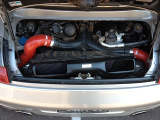
I just did my pipes using the Forge Motorsport kit. Nice price! Their pipes come with what they call "jubilee clips" which we call hose pipe clamps, that clamp the pipe to the billet fittings. I found that if you have this type of setup, you need to install the clamp right back as far as you can for the upper pipes where they pass through the firewall. In hindsight it would have been easier to use the kind of clips that the samco hoses use, as the hose pipe clamp screw can foul the firewall if you put it too close to the billet fitting. The right-hand upper hose was particularly difficult to get in the right place. I also did not need to remove my wheels or the wheel arch lining, only jack up the car (use the centre support NOT the engine casing and put car on jack stands), so this saved a lot of time. I also took the opportunity to install my Agengy Power dual flow air box too! Here's the end result..
-
Cayenne Valve Body Replacement DIY Hello Everyone. Please find my first tutorial submission. Replacing the Valve Body (aka valve chest) in a 2003 Cayenne Turbo Symptoms: Very harsh shift from 1-2-3 when under load (like getting rear ended by a truck) Hesitant shifts and flaring when driving normally. "Clunky" shifts. Vehicle has travelled around 210,000km. Fluid has never been changed (dealer said is was not necessary-which is not true!) After doing lots of reading it seemed like the valve body (VB) was the likely culprit Author darrinsmith Category Cayenne (9PA, 9PA1) - Common Fixes and Repairs Submitted 02/10/2013 02:09 AM
-
DIY is awaiting approval in Cayenne common fixed and repairs. Hope you all find it useful.....
-
Hi Hilux2400 Disconnecting or changing the battery on 996's should not mess anything up. The only thing you really need to reset is the windows. You just wind the window all the way up and then hold the switch for 4-5 seconds to re-set the upper limit. It's actually in the owner's manual from memory. Also if you have a PCM you'll need to let the car "equilibrate" in open sky for 10-15 minutes. Again this is also in the manual. If your transmission is going into limp home then you may have a bigger problem. In that case you should get the durametric software. It'll only take one job to pay for itself. Cheers from Oz DS
-
Cayenne Valve Body Replacement DIY
darrinsmith posted a tutorial in Cayenne (9PA, 9PA1) - Common Fixes and Repairs
Hello Everyone. Please find my first tutorial submission. Replacing the Valve Body (aka valve chest) in a 2003 Cayenne Turbo Symptoms: Very harsh shift from 1-2-3 when under load (like getting rear ended by a truck) Hesitant shifts and flaring when driving normally. "Clunky" shifts. Vehicle has travelled around 210,000km. Fluid has never been changed (dealer said is was not necessary-which is not true!) After doing lots of reading it seemed like the valve body (VB) was the likely culprit. You can either replace with a new VB or have your old one re-built. If you replace the VB with a new one, you also need a new transmission control unit, and the problems will most likely re-appear. I went the re-build route and chose RevMax converters based on other people's experience. Note that RexMax don't ship outside the USA, so as I live in Australia, I used my wife's USA2ME mailbox, and they sent it on to me. I also had to send my old core in as they didn't have one in stock, but I'm glad I did, as there are several versions of VB depending on the year of your car. They rebuilt it within 48 hours. As you will need to drain and re-fill the trans, I won't be covering that in too much detail as it is covered extensively elsewhere (see my reference links below). Parts list 1) Auto trans filter 955-307-403-01 2) Auto trans filter sealing O-ring 955-325-443-00 3) Filler Hole seal O-ring 955-321-379-00 4) Crush ring for transmission drain hole - sorry didn't have PN for this as I forgot to order it! I re-used my old one. 5) 3 x Long VB retaining bolts WHT 000 321 6) 11 x short VB retaining bolts WHT 000 324 7) Transmission pan gasket 955-397-016-00 8) Case (12 quarts) of Mobil ATF 3309 or Toyota type IV Transmission fluid (It is the same stuff do don't panic if you can't get Mobil or Porsche branded fluid) Tools List 1) 1 x micro torque wrench (range 2-20 ft-lbs) 2) 1 x normal torque wrench (for torquing the fill plug to 70 ft-lbs) 3) T40 Torx bit to remove drain plug 4) 17mm Hex bit for fill plug 5) 10mm socket (apart from the drain plugs everything is a 10mm socket) 6) general other sockets and screwdrivers. 7) Durametric software to read transmission temp and re-set adaptation (you can get buy with a temp probe on a multimeter, but it was much easier to use the software, and IMHO if you are attempting a job like this you really should get it. It'll pay for itself on this job alone). 8) A willing assistant to help with the re-fill procedure. Reference - read this stuff first and print out the relevant pages 1) Official method for removing the valve body http://www.inkilino.es/Porsche_Cayenne_02-06/AUTO%20TRANS%20GEARS%20CONTROL.pdf 2) A really nice tutorial on draining and re-filling the transmission in addition to the ones on Renntech by ECS tuning http://bd8ba3c866c8cbc330ab-7b26c6f3e01bf511d4da3315c66902d6.r6.cf1.rackcdn.com/CayenneTransmission.pdf 3) there's a brief write up at club touareg that I used as a starter http://www.clubtouareg.com/forums/f73/transmission-valve-body-diy-on-2004-touareg-v8-09d-trans-64189.html Part 1 Removing the Pan and Valve Body 1) Remove the underbody protection panel. 2) There is a 2 peice bracket that holds the protection panel up, unbolt it in the centre and side and remove it. 3) My car had a strong bash plate over the rear of the transmission pan, it will need to be removed in order to access the rear pan bolts. 4) Drain the fluid from the pan (First make sure you can budge the large fill hole-It's really tight I had to use a big metal bar to crack it, once it's "cracked" you can then remove the T40 torx drain plug). Best to drain the fluid cold after it's been sitting overnight. You'll drain an easy 5-6 quarts here. 5) Remove the ATF Pan bolts (all 10mm) and save them - they can be reused. 6) Gently knock the pan to break the seal and remove it. 7) Remove the 3 10mm retaining bolts from the ATF filter and remove the filter. Make sure the seal ring comes out too. More fluid will come out. Discard filter and o-ring. You should not be able to see the valve body as below. Take a picture and make notes as to which wire goes where. It's actually not that complicated as the wires will only really go in one spot when you re-assemble. You also need to note how the selector shaft engages with the VB as below. Again this looks tricky, but it was dead easy to put back together. Here's a close up of the shift solenoid wiring harness showing the green connectors in the black housings. Here's a pic of the other side. You can see another solenoid, plus the two pressure switches (gold colour) and up the back the large white output shaft speed inductive pickup connecter. Note how the white connecter clips onto the bracket and also how the wiring is tucked under the bracket. 8) Now work your way slowly around the 5 solenoids on the shift selector side removing the green connectors. I used a small screwdriver to depress the little clip and lever them out. You should not need to use hardly any force on these. You don't want to damage them at all. 9) Remove the 2 black cable plugs at the rear of the VB and the single solenoid green connector at the front of the VB. 10) Next pull off the plug for the input shaft inductive pickup. This is located at the front of the trans, right up in the "guts" of it. It looks really tricky, but using a long screw driver it came right out. Putting it back in was also really easy, so work slowly and don't panic. 11) Next pull off the two cables from the gold pressure switches. They just pop right off. 12) Remove the bolt holding the ATF temp sensor (2 orange wires) and pull the sensor out. It's held in by an o-ring. Save the bolt and retaining bracket. Don't remove the sensor from the wiring harness, just let it dangle with the rest of the wiring harness. 13) Remove the large white connector at the rear of the VB (output shaft inductive pickup) from the bracket and unclip the white connector. 14) Remove the steel bracket and save it and it's bolts. 15) Remove the 2 gold pressure sensors (if you get the VB rebuilt you'll get new ones, but hang onto them just in case). Now all the wires should be free. Tie or secure them gently so they're out of the way. The VB is very heavy and will also dump a heap of fluid when you remove it, so you don't want to snag the wires at all. 16) Now remove the valve body by removing the 14 bolts around the outside. They are all 10mm. I removed all but 2, one at the front and one at the rear, then slowly loosened them allowing the VB to tilt forward. This allows some of the excess fluid to run out. There is still easily 2-3 quarts of fluid in there so it's messy. Again take care the VB is very heavy, expecially if you are working on your own. Here's the transmission with the valve body removed. Note the black wire in the centre of the transmission is the output shaft inductive pickup that is attached to the big white connector. Clean up the VB and send it off to be rebuilt. Part 2 Installing the VB 1) get all your parts together. Note the valve body retaining bolts CANNOT be re-used, so make sure you got new ones. 2) Gently place the VB in it's position. Make sure the selector shaft mates correctly with the VB. Mine almost just fell into place itself. Also make sure that none of the wires are snagged especially the output shaft wire (big white connector).If you've secured them out of the way this won't be a problem. I put in 2 bolts to start with to get the position right and take the weight. Only do them barely hand tight. This is really important as the torquing process will be ruined of you do them up too tight to start with. 3) Put in the rest of the bolts and tighten them up by hand so the VB is in place and mated correctly to the transmission. If you get the bolts in the right place, you'll be fine. Don't do them up too tight! 4) Now the bolts need to be torqued in 2 stages. Initially using your micro torque wrench to 6 ft-lbs (8 nm) and then finally through an angle of 90 degrees (quarter of a turn). I had an angle gauge, but I couldn't find a good spot to use it against the transmission body. So in the end I just torqued them by "eye". 90 degrees is easy to judge. So to re-cap. Torque all bolts initially to 6ft-lbs and then once you've torqued all 14 bolts, the go around and torque them AGAIN through 90 degrees. If you have one of those fancy digital torque wrenches, it may also do angular torque for you. Here's the new VB installed in the transmission. Note the wires are hanging neatly to the side. 5) Reinstall the two gold pressure switches (torque to 3.25 ft-lbs/4.5 nm) and also re-install the bracket you removed that holds the white output shaft inductive pickup wire connector. Make sure the wire is routed correctly under the bracket and attach the white connector to the bracket as below. 6) Connect the other white connector from the output shaft pickup 7) Replace the ATF temperature sensor using the bracket and the bolt. Note the wire points to the rear of the VB. Torque the bolt to 7.5 ft-lbs/10nm. 8) Plug in the 2 cables for the gold pressure switches. 9) Plug in the cable for the input shaft inductive pickup. This is the one that's right up at the front of the transmission. For me it went straight in no problems at all with a nice positive "click". It looks a bit daunting, but was surprisingly easy to re-connect. 10) Plug in the remaining green six green connectors, and the two black connectors at the back of the VB. Compare the wiring layout to the picture you took before you unpluged them all!. If you didn't take a picture, don't panic, the wires only really go one way, just make sure they're nice and neat. As a guide the orange temperature sensor wires go under the green/brown solenoid wire. 11) Next reinstall the ATF filter using the new O-ring. Torque the 3 bolts to 7.5 ft-lbs or 10 nm. It should all look like this... 12) Next put the new Pan gasket in place on the pan and using the old pan bolts install the pan and torque the bolts to 7.5 ft-lbs or 10nm. I put a little drop of Permatex blue threadlocker on them for good measure. Here's a picture of the nice clean pan and new gasket next to the old gasket. Make sure the pan and magnets are all clean. Just wipe it out. I didn't want to use degreaser in case it contaminated the trans fluid. My magnets weren't too dirty. I've seen pictures of this trans in an Audi and the magnets looked like little Chia pets!! Install the small drain plug and new crush ring (doh!) and torque to 21 ft-lbs/28nm. 13) Now cold fill the pan until fluid comes out the fill hole. It took about 4 quarts. I used a $8 garden sprayer, and put about 2 feet of clear hose on the end with a hose clamp. This allowed me to have the pump bottle at the ground, and put the plastic tube into the transmission so it hooked over the fill tube. It worked brilliantly! Here's a picture of the bottle I used. Here's the top of the setup. You can see the plastic tube going into the transmission. I also had my multimeter temp probe in there, but it turned out I didn't poke it in far enough so it couldn't pick up the temperature. I used the Durametric software instead. 14) Now for the "hot" fill procedue. Make sure your fill bottle is full. I ended up using a total of 10.5 quarts to refill the transmission (this is more than a normal fluid change as the VB has been removed), so I had to refill the fill bottle half way though the procedure. You have to move quickly as once the temperature starts to move on the transmission it only takes about 5 minutes to get to 40oC. I set my laptop up in easy reach (make sure it's fully charged or better still connected to AC) and also had all my bottles of ATF at my feet. 15) Have your assistant start the car and you start filling the transmission. I added another 4 quarts in a few minutes. Ask your assistant to move from P to R to D and back again with about a 3-4 second pause between each shift. Do this once. 16) Keep filling the transmission, and watching the temp on the software. Once the fill bottle was empty quickly re-fill it, re-pressurise and keep filling. Get your assistant to do the shift sequence again. I found that at about 32-35oC the trans was getting full. Fluid will start to leak back out the hole, so make sure you've got a drain pan under the hole! 17) Keep filling and execute another shift sequence. At about 38oC I got another shift sequence done, and then put a but more fluid it. 18) At 39oC fluid started coming out the hole a bit faster, and at 40oC I quickly pulled out the tube and put in the fill hole socket. Torque it to 70 ft-lbs. 19) Stop the car, using the durametric software execute the Reset Adaptation command for the transmission. After that go for a test drive! As the transmission control unit is in learn mode, you should try to do all sorts of driving styles. This has solved all the shifting problems I had, it really drives like a new car. Even my wife commented on how smooth it is now. Check for leaks and replace the underbody panels etc. Enjoy your new car! -
I just got my valve body back from Revmax. Should reinstall this weekend hopefully. It's 38oC here at the moment, and my garage is like an oven, so I'm waiting for it to cool a little..... I've been taking pictures for a DIY also. Disasembly was surprisingly easy, abeit a little messy. Mental note unlike an engine oil change you want to wait till the trans has cooled overnight and the fluid drained down. The valve body holds a couple of litres of fluid. My trans is at 210,000 km, the fluid was black :-( magnets weren't that bad, I've seen pictures of some that look like chia pets! Local dealer has NEVER done a fluid change! The parts guy confirmed they had never ordered or sold a trans filter! WOW... Stay tuned for DIY with pics....
-
The ctt can use a lot of oil. When my wife drives it, I will have to top up quite a bit, also the left hand pressure hose recycles oil mist, so if the seal is bad it will leak a heap of oil and cause ou to have to top it up a lot. I fixed the seal recently and there was about a litre of oil in the lower hose! Like loren none of my previous 8 p cars have ever used oil between changes. Even our current 996 turbo doesn't use a drop between services, and I know the wife drives that hard! You can't miss that whistle. just the cayenne turbo. It makes sense when you see how it deals with oil vapor through the left hand turbo. Don't be concerned, just change you oil regularly. My ctt is at 230000 km and still goes well. I can't be bothered changing it cause it runs so well. cheers DS
-
Hi! Would someone (perhaps Loren) be able to please post the instructions for removing and replacing the roof lining for a MY2004 996 cabriolet (with glass window). I did search and found people talking about, but no instructions. Thanks! DS
-
I switched to shell helix ultra 5w40 at about 140000km. The engine was a little rough at higher revs on Mobil 1. Vehicle is now at 221000km and the engine runs smooth as silk. I change oil and filter every 10000km. Helix ultra is on the approved list I'm fairly sure. I understand that it's important to use an approved oil especially for the turbos as it has low ash. On the cayenne the engine oil vapor is recycled through the right hand turbo. I recently fixed the seal on the pipe and there was about a liter (no joke) of oil in the pipe! All of which had been through the turbo at some point. (note: draining the pipe is now on my 10000 km service work list). I still use mobil 1 in my 996tt though. The cayenne seems much more fussy with its oil. The 996 not so. A mechanic friend of mine who does a lot of Mitsubishis told me the newer ones with variable valve timing are also very fussy about the grade of oil and run a bit rough if it's not the correct viscosity. The weather is gets really hot here (Christmas day was 40oC) but a 5w50 is way too "thick" for the cayenne's valve timing gear, and there's no need for a zero winter grade as we never get much frost in winter, and definitely no snow! Cheers! DS
-
HiI'm in the process of replacing my valve body and need to get some fluid.The Mobil Australia fluid selector shows either Mobil ATF 3309 or Mobil synthetic ATF.Any thoughts on using the synthetic? As there will still be a small amount of residual "old" ATF in there.Otherwise I'll go the Toyota t-IV fluid perhaps as the Mobil is special order only in Perth....ThankDS ---Edit--- Just spoke to the Mobil distributor here in Perth, they only bring in 3309 in 20 litre lots. The reason he told me was that they sell that exact fluid to Toyota who re-sell it in 1 litre lots as their type IV fluid. There is an exclusive arrangement between Mobil and Toyota here so that only Toyota can sell that fluid in 1 litre lots. So there you go..... --Edit#2--- Just for a laugh for all you readers, just priced 1 litre of trans fluid from local dealer AUD$63.60 and that is "trade" price. (1AUD is roughly 1 USD at the moment!)
-
Anyone else able to post a couple of pics? Thanks DS
-
Where is the phone module located?
darrinsmith replied to Blob's topic in 996 Series (Carrera, Carrera 4, Carrera 4S, Targa)
The Denison will always produce this error as it does not fully emulate the factory phone module. I have a Denison in my cayenne tt and a mobridge in my 996tt. The mobridge doesn't make the error and the phone book works with iPhones. The Denison can't load the phone book from an iPhone. The sound quality on the mobridge is also far superior to the Denison. The only thing the Denison does better IMHO is that it remembers the "shuffle" or random track sequence on the iPod between power cycles. The mobridge reverts back to "normal" track sequence even when you switch between radio and iPod. And of course the Denison is marginally cheaper, but not by much. I hope this helps! Cheers DS -
Thanks, but I need to be able to show them how the top goes. It doesn't look right, particularly the way it goes around the metal arm. Unfortunately Perth is a small city, and unless you drive a Ford or a Holden (GM for our American friends) then no one really wants to touch it. You can also count the number of Motor trimmers (that's what we call them) on one hand. The dealer also says they can't recommend anyone. My wife's Aunty makes curtains, so I'm sure she could repair it, but it would really help to be able to see exactly how it goes together and what attaches to what. Thanks! DS
-
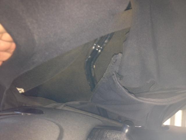
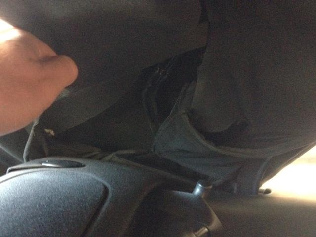
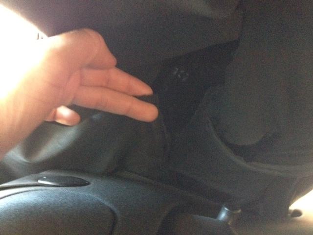
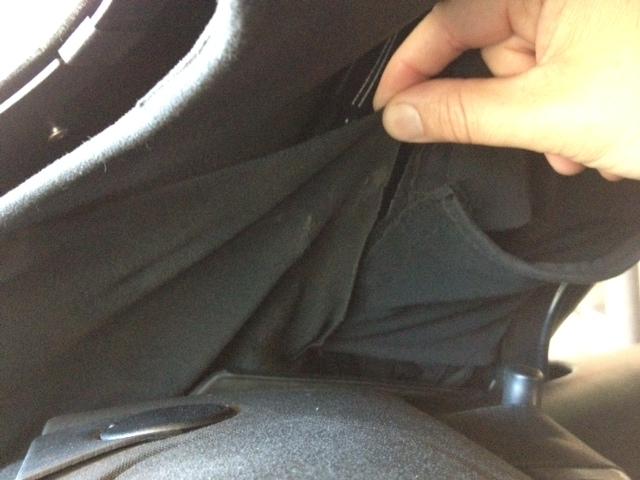
Hello and Merry Christmas from down under! My 2004 Cab's (it's a turbo but should be the same as regular cabs?) internal lining is all messed up around where the main support arm folds. It looks like someone's had a go at it before and mucked it up. It doesn't look right, and there's a loose flap of material that hangs down and is always getting caught in the folding arms. It just came back from the dealer after they replaced the drive mechanism, but they didn't remove the top, and they don't want to fix it, only replace the entire lining. the rest of the lining and top is in good condition, so I was wondering if a handy cab owner (same model year) would be able to post some pictures of how all the bits of fabric go together and how they are mounted and work around the folding steel arm. I have the workshop manual but the diargams are very unclear, and there have been several revisions over the years. I've posted some pictures below so you can see the trouble I'm having. It's the same on BOTH sides of the car. Thanks again! Darrin Smith Here's the lining as it is with the roof closed. You might be able to see the bit of lining laying toward the rear. Here's me holding the loose bit of material up towards the rear. Again me holding the loose material up toward where I think it should go. A close up of the lining showing the loose flap again laying on the roll over bar. Here's how I think it should be? attached to the other bits of material? but I'm not sure how it all works around the metal arm, I think the velco bits are all wrong.
-
Tried those maps but there is practically zero diffrence between the 2004 and 2008 maps.... Bummer!
-
Ok had a productive session with a friendly tech today. As I suspected the correct way to code the unit is. 1) Disable mobridge using the toggle switch. 2) connect PIWIS and go into the PCM. 3) in the next available slot (#3 on my car) code the phone module. 4) do not code a CDC if one is not already fitted to the car (as in my case) the PCM will automatically find the mobridge and install it as a CDC. 5) allow PCM to reboot. It will display the "system error phone not found". 6) click "OK" using the right hand selection wheel 7) while the car is still switched on, re-enable the mobridge using the 5 toggle method on the toggel switch. 8) PCM will then find the phone module and the ipod (CDC) after a few seconds. 9) pair phone and connect ipod...enjoy...
-
Hello! I (aka the dealer) is having trouble activating the phone module on my PCM to allow my newly installed mobridge to show up. So I was wondering if someone could post the actual procedure? Here's the background... Firstly and most importantly, car is a MY2004 996tt cab with PCM. Now it is a ROW (Australian) car, which means that while the PCM has the telephone buttons on it, the phone, sim draw AND phone prep (which I believe is fitted standard in the US) is NOT present in this car. It also does NOT have the CDC. (mainly cause they were both $2K options!). I have the same setup in my cayenne but it runs a dension GW500/BT module. Mobridge (w/bluetooth) is installed and the CD/ipod is working fine. Dealer did manage to get it working before, but it took them hours (I paid!) cause they are basically clueless with anything other than an oil change. They however removed the mobridge and my smarttop unit while they were doing a repair due to "problems" they were having with thier PIWIS. The car has just come back after having some roof components replaced. I waited 3 (yes three) weeks for them to figure out how to calibrate the roof with the new system tester. They told me there is a worldwide software fault with the new Panasonic based system that prevents the roof calibration from completing (more likely they just don't have a clue, this is also after Porsche screwed my on my rear spoiler repair because I was 10 (ten) days out of warranty when it was identified, even though it had been leaking for months, but I digress.....) Anyway on my cayenne the procedure for the dension was really easy, install unit, and while it is active (not in service bypass mode) go into the PIWIS, into PCM, into MOST ring actual devices, and add "phone" to the next available slot. Reboot car, and tada! phone module working.... However the mobridge seems much more invasive than the dension, so they struggle with it. My questions are 1) should the unit be in bypass while trying to program the phone module (I assume this was the problem last time as the unit was NOT in bypass and it was screwing with thier PIWIS). 2) They also tried to code the CDC, but I beleive this is unneccesary. The head unit seems to be able to figure it out itself given the fact the ipod is working fine at the moment as a CDC. 3) Should the phone be coded to the next availble slot in the ring, or do we need the leave a space for the CDC? I assume again next available slot, and the CDC will sort itself out. 4) I believe a lot of the issue thay are having is cause they just don't know how to drive the new system tester, and they are learning at my expense, and yes there is no other dealer within a 3000km radius! 5) once phone is coded, shut down car, reactivate mobridge and re-start car? I would appreciate any tips or tricks anyone can provide. BTW just priced a cabin air filter, AUD $98 (about US$101) I told them to shove it and bought it from pelicans for $19. (This is what I have to work with.....) Thanks again! Darrin Smith
-
I guess the topic says it all. I have a 2003 cayenne turbo with the CD based PCM 2.1 (with Bose audio). Porsche Australia are not producing any map updates for the CD based cars, only the DVD based cars, so my map is stuck at 2004. When you live in the fastest growing area of Australia, that's a problem. Can anyone comment if it is possible to add the NAV drive from a wrecked later model car (say a 2005) and connect it to the old PCM. I assume the NAV drive connects to the MOST ring, and then would require the dealer to code it to the ring with the PIWIS? Alternatively, if I can get a complete later model unit with the drive, can I retrofit that with the old BOSE gear. I use my car a lot for visiting clients, so having a working NAV is a real necessity for me. Thanks! DS
-
mobridge ipod in 996 w/PCM
darrinsmith replied to darrinsmith's topic in 996 Series (Carrera, Carrera 4, Carrera 4S, Targa)
Hi I got this response from Mobridge, looks like it's the PCM in the 996's. Bugger. "Your car is actually the culprit here. On startup, disc change, manual track incrementing etc, the PCM turns off random. It's impossible to tell if the user has pressed the button or the radio is doing this because all our unit gets told is to turn random off. Dension may have put some trickiness in for this or maybe the PCM in the 2004 is doing this. The PCM in the 911 is vastly different to the Cayenne version even though functionally they do act the same way." Oh well, it's worth the trade off for the mobridge's far superior telephone sound and functions, as I use the phone in the car a lot... Cheers from down under! -
Hi I finally got around to installing a mobridge ipod/bluetooth in my 04 996 turbo with PCM. The car is a ROW so I had to get the dealer to activate the phone module on the PCM but now it's all working fine. The only really super annoying thing is that every time you restart the car, the unit forgets the "random" track order setting on the ipod (it's a supported nano). I also have a cayenne turbo with a dension GW500 and it is quite happy to remember the random setting with the same ipod. I've flashed the latest firmware, so now I'm not sure whether this is normal for the mobridge unit (I hope not cause it a serious flaw) or whether it's just a difference between the PCM in the 996 and the cayenne. Having said that the mobrdige phone module blows the dension one out of the water (no phone not present erro, phone book loads in the PCM with an iphone, sound is ultimately superior). Any 996/PCM/mobridge owners to comment on this one? Thanks DS
-
mobrige firmware update
darrinsmith replied to jaybart's topic in 997-1 Series (Carrera, Carrera 4, Carrera 2S, Carrera 4S)
Sorry to bump this post, but can anyone advise how to determine whether you have a gen 1 or gen 2 bluetooth on the mobridge ABT2010? My details are BL Version 01.01.01 SW Ver 01.09.04 BT: HW200-SW321 Thanks! -
Hi, I have had some brand new 18" sport techno wheels fitted to my 2004 996 turbo cab. The car was in an accident and the insurer insisted that I had to have no larger than 18" genuine Porsche wheel to replace the old Gemballa 18's which were damaged in the accident and were no longer available. So I got them to fit a complete brand new set from Porsche! (nice). They have only been on the car about 3 months, but I am having constant issues with the metal valve stems leaking air. It has been to the tyre shop several times, and the latest shop (they are actually clients of mine) took the tyre off the wheel and showed my how the valves fit. Bascially the rubber seal on the inside of the valve is prone to leaking. We cleaned up the seal and re-seated it (there was a small amount of corrosion that had rubbed off the inside of the wheel), and tightened the outer retaining nut as much as we dared, but it's still leaking, especially if you put any sideways pressure on the valve stem. I've never had this problem before, so I'm a little stumped as to how to proceed. I assume the valves came with the wheels? Can anyone suggest what I can do? Thanks DS