Welcome to RennTech.org Community, Guest
There are many great features available to you once you register at RennTech.org
You are free to view posts here, but you must log in to reply to existing posts, or to start your own new topic. Like most online communities, there are costs involved to maintain a site like this - so we encourage our members to donate. All donations go to the costs operating and maintaining this site. We prefer that guests take part in our community and we offer a lot in return to those willing to join our corner of the Porsche world. This site is 99 percent member supported (less than 1 percent comes from advertising) - so please consider an annual donation to keep this site running.
Here are some of the features available - once you register at RennTech.org
- View Classified Ads
- DIY Tutorials
- Porsche TSB Listings (limited)
- VIN Decoder
- Special Offers
-
OBD II P-Codes - Paint Codes
- Registry
- Videos System
- View Reviews
- and get rid of this welcome message
It takes just a few minutes to register, and it's FREE
Contributing Members also get these additional benefits:
(you become a Contributing Member by donating money to the operation of this site)
- No ads - advertisements are removed
- Access the Contributors Only Forum
- Contributing Members Only Downloads
- Send attachments with PMs
- All image/file storage limits are substantially increased for all Contributing Members
- Option Codes Lookup
- VIN Option Lookups (limited)
Leaderboard

-0001-0001.thumb.png.17f5bb25bf8ec261a17c21e6321c8492.png)


Popular Content
Showing content with the highest reputation since 09/02/2025 in all areas
-
Welcome to RennTech If you do not have access to a wiring diagram for the vehicle, probably the easiest way to check the ground is to pull the bulb in the light and use a multimeter to check the condition of the ground at the bulb socket.2 points
-
We have used them here in the US for years at MUCH colder temperature's than you get without ANY issues. Put on the adaptor, add external magnets such as the Filter Mag, and enjoy both better filtration and peace of mind.......2 points
-
1 point
-
Try 97861 point
-
Sometimes these systems store a lot of secondary codes that confuse what is really going on. I would start by clearing all the codes and then see what comes back.1 point
-
Try 89641 point
-
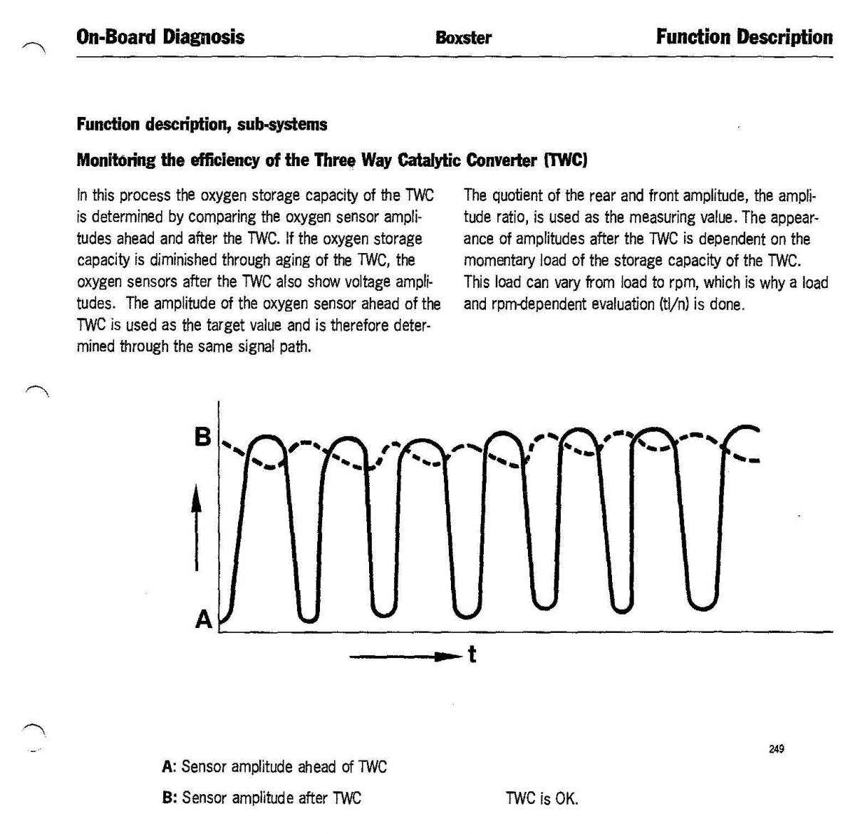
You should be comparing the voltages for the O2 sensor ahead of the TWC to those after the TWC: The voltage curve for the senor after the TWC should be a relatively straight line, the one ahead the should be a sine wave like pulse; if the voltage curves are both sine waves, the cat is toast.............
 1 point
 -
Non, push down with one hand, squeeze the ribbed bottom ring with the other hand and pull up, this is not as easy as it looks, succes.1 point
-
That's trouble. Recheck connections. Use Deoxit on the plug-in connectors. Use fine grit sandpaper (and clean off the grit left by sanding) on the nutted connections. Is it possible you shorted something out as you removed the battery? Were the battery cable ends removed at the battery? Is it the original alternator? It might be possible that it's only the voltage regulator module.1 point
-
Your alternator is not functioning, running you should have 14.5V DC. Pull the alternator, check the wiring connections to be sure they are tight and seated, if they are you are in the market for a voltage regulator..........1 point
-
I'd start with checking the alternator, is it putting out 14.5 V DC at idle? If not, I would check to make sure you properly reconnected the wiring.1 point
-
What are your voltages? Resting, idling, driving above 2000rpm? There are gizmos to help with this monitoring - Antigravity Batteries has a battery tracker. Others plug into the cigarette lighter. Do you have any codes (can be read with Durametric and other (OBDII) readers)? I've read stories on Rennlist about induced electrical noise in the sound system even when the sound system is not turned on. Might your alternator be damaged or no longer have a high quality ground? Could the noise be mechanical (transmitted noise)? You did change pulleys. Run the car a few minutes without the serpentine belt and see if the noise is reproduced.1 point
-
N 104 707 03 round hd. screw US MSRP $1.91 (each)1 point
-
Try 45051 point
-
You need a Porsche specific scan tool to see the faults, something like the Durametric system or a PIWIS system, no other scan tools will be able to see the faults.1 point
-
If you get a honk it means you have at least one zone open or one (or more) fault codes. You will need a Porsche compatible scanner to get the fault code and report it here. It should narrow down exactly where the problem(s) are.1 point
-
Because it is a 2005 engine, it would most likely have the oversized third generation IMS bearing in it, which means it cannot be removed without total disassembly of the engine because it will not fit through the opening in the engine cases. One way to know for sure would be to pull the trans, clutch and flywheel off and look at the nut on the IMS bearing center bolt; if it is 22 MM, you have the oversized bearing, which was the only one to use that large a nut.1 point
-
The engine serial number would have been built in late 2005 or early 2006. Porsche rebuilt engines always get the latest parts and a warranty. To be sure you would have to open the engine to get the IMD diameter. If you want insurance then you can install one of the 3rd party IMS oiler solutions. IMS Solution: Oil Fed Plain IMS Bearing - No Ball or Roller Intermediate Shaft Bearings LNENGINEERING.COM IMS bearing failures are expensive. The IMS Solution is the only permanent solution to the IMS problem. Proven protection and the industry’s best warranty.1 point
-
I'm heading to the track for the first time and Shenandoah circuit at Summit Point apparently has a little crest where some people catch air. I don't want the rollover bars to scare the crap out of me while on the track. Any ideas?1 point
-
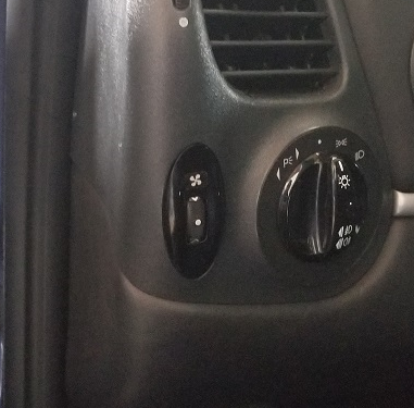 Rotary Switch to Manually Turn on the Cooling Fans Porsche 996/986 So the rotary switch has a fan symbol that lights up the same colour as the rest of the buttons in the car when the headlights are turned on. To turn on the low speed fans, rotate the dial up and the symbol lights up blue. Turn it down for the high speed (and the engine fan as well) and it turns red. The automatic function of the fans is not affected by this at all. In fact, the indicator lights will turn on when the car switches the fans on, so you can tell when the high or low speeds are on, which is cool. So the function of the rotary switch will be: -when at rest and headlights/parking lights are not on, fans are not on and the indicator light is not on. -when the dial is turned up, low speed fans are on and the indicator light illuminates blue. -when the dial is turned down, the high speed fans are on along with the engine bay fan and the indicator light illuminates red. -when the headlights/parking lights are on, the indicator lights orange. We will need 1 RGB LED, 1 diode, 1 resistor of 500 ohms, 1 resistor of 1000 ohms, 1 resistor of 5000 ohm (this may be different depending on the LED you use) Here is the wiring diagram that we will follow to make this work. First you need the headlight level switch. It was available only on the 996.1 cars and is part number: 996 613 230 01 You need to disassemble it, as all the circuitry inside will be replaced, and the headlight symbol removed. Remove the circuit board now, as it will be replaced with one we will make from scratch. Remove the LED as well and all wiring inside. Now you need to make a new circuit board to replace the old one. You need to visit an electronics store and get Ferric Chloride and copper clad board. Cut a piece of board to match the size of the old circuit board. Cut it roughly with a saw and then use a file to get it down to exactly the shape and size you need. Peel off the protective film and then lightly sand off the bluish film off the board until you have only copper exposed. Now you need to draw on the circuit onto the copper with a sharpie. I did it backwards, but it is soo much easier if you sand off the blue film and then draw the circuit. The chip will now go into the Ferric Chloride. The liquid will eat away all of the copper except for the parts you drew in sharpie, as the liquid does not react with it, leaving the copper underneath protected. When you take it out of the Ferric Chloride, you will have your chip. Clean off the sharpie with rubbing alcohol. Now you will drill 3 small holes in the bottom of the chip for wires to attach to. You will need to solder in bare solid wire into each of the holes. One contact will be for high speed, one for low speed and one for ground. Here you see the chip in place with the wires leading out of it. Each wire will need to be soldered onto a contact in the switch that leads to a pin. Now for the LED. You need a frosted 5mm tri colour RGB LED with a common cathode. The ground for the LED will go to pin 4 in the switch - same as the grounds for the high and low speed for the fans. The lead for the green will go to the 3rd pin. There is not enough pins for everything, so you will need to add more. I did this by putting a noche in the base of the switch to allow a couple wires to run out of the switch to another connector. I just picked up a male/female 2 pin connector from ebay like the one below. You will need resistors for these LEDs. Green is much stronger than red, so I used a 500 ohm resistor in series for the red LED, and 5000 ohm resistor in series for the green LED. 1000for the blue. You will need to test the light intensity and how the colours mix to get you the orange you need using different strengths of resistors to match the rest of your buttons. There is not much room inside the switch, so I placed my resistors and the diode outside the switch, which you can see here. Next is to make the fan symbol. Sand off the headlight symbol from the indicator piece. I had a tiny fan laser cut by a shop for me onto vinyl, which I then placed on the piece and painted black. Removed the vinyl, and now there is a perfect symbol of a fan that the LEDs will illuminate. Place back in the switch and now put it all back together. Switch is done. Now to wire everything up to the switch. The diode has to go where you see it in the diagram. It allows current only in one direction. Again, there is no room for it in the switch, so I have it in the wiring outside the switch. The diode will allow current to flow from the power supply for green LED to the red LED (this will make orange). You may need to test different resistor values to get the right colour of orange. Now to make it all work. We will need four 12v relays. I installed all 4 relays in the relay tray above the fuse box to make it look as OEM as possible. But they could go anywhere. You will need 4 relay plug with the metal connectors if you do what I did. Part number is 928 610 511 00. You need to locate the 2 low speed fan relays and the 2 high speed. The low speed relays are numbers 19 and 21, while the high speed relays are 20 and 22. Disconnect the battery in the car. First remove the fuse box panel. It is held on by 4 screws. You can then just pull it out. The relay box is above it. It is best to remove the relay box. It is held in place with a single nut, and clipped in on the opposite end. Flip the relay tray around so you have access to the back. I removed plugs that were in my way. Now use the wiring diagram from earlier to make the wiring connections you need. The proper routing and connections of the new wiring is all there in the diagram. The relays labeled as normally open or normally closed are the new relays you are adding. The purpose of these relays is to turn on and off the appropriate LED colour to indicate whether high or low is on, and to turn off the orange (if headlights are switched on) when fans are in operation. If you want the engine bay fan to also turn on with the high speed fans, then you will need to run a wire splitting off from the wire runs from pin 85 from relay 22 all the way to the back behind the rear passenger. There is another relay box there. I removed the rear quarter interior panel to help with running the wire as well as the bonnet/engine cover release panel trim. But you don’t have to, just tuck the wire in. Remove the carpet in the back to expose the relay box. It is on the right and is held in place with a nut in the centre and 2 screws on the right. You can see the wire I ran from the front. Flip it over and find relay number 8. You want to tap into pin 85 of that relay. Put it all back together. Now wire up the switch. The wire from pin 85 from relay 22 goes to pin 1 of your plug for the switch. The wire from pin 85 from relay 21 goes to pin 2. The wire from pin 87a from the normally closed low speed relay (see diagram) goes to pin 3. The wire from pin 87 from the normally open low speed relay (see diagram) goes to the connector you added to the switch - green wire The wire from pin 87 from the normally open high speed relay (see diagram) goes to the connector you added to the switch - red wire From the switch, we have a ground wire. This can go to any ground point in the dash. I found a spot close to where the switch goes and grounded it there. There is one last wire, and this is to get power to the red/green LED when the headlights are on. You can wire this to any switch in the car that illuminates. I took power for this from the intermittent wiper in the dash for power. Now with everything wired up, this should work. With the car on, but no headlights and the switch is at rest, there should be nothing. When the headlights are turned on, you should have the fan symbol light up in orange. Turn on the high speed fans, and you should have the engine fan and the 2 front fans on and the symbol should be red. On low speed, only the 2 front fans will be on at low speed and the symbol should light up in blue. The car will still turn on the fans automatically, and when it does, the fan symbol will also light up to let you know the car has turned on the fans at either high or low.1 point
 -
Hi..I live in rainy Ireland and this has been a real problem in my 996 Cab. I brought your water drain diagramme to my garage and they removed the interior side panel to find an easy solution. A number of drain tubes collate into a collection point like a mini funnel which had built up a pot of sludge and water could no longer flow through same and out of the car...so diverted to the back foot wells. Who thinks up the stupid systems??1 point
-
Today I did front final drive gear oil change. This DIY will show you how I did it. Since I had a hard time to access the drain plug, I removed fill plug and used a pump to suck out the final drive oil. Worked really well, and helped avoid messy drain, which puts oil onto the lower axle carrier frame too. FSM calls for change quantity of 0.42L, and I managed to remove about that much from the drive, so I feel confident I got it all. Used empty oil can go suck old oil into it, and another empty oil can to put same amount of new oil it, making sure I fill with what I removed. I actually filled the new oil can with maybe 1/4" more oil, to accommodate for some oil that pump cannot take out of can, and some oil left in tubing. Oil used for change: Mobil Delvac 1 full synthetic gear oil 75W-90 (direct cross reference to Shell TF0951 - factory fill oil) Oil refill quantity: 0.42L (bit less than half a quart) New fill plug part number: N 902 818 02 Fill plug tighten torque: 25.8 ft/lbs Fill plug removal tool: ratchet, extensions (at least 6"), 5mm hex socket, shop towels Look at this DIY before you do the change. Make sure you have all materials and time to do it. Expect about an hour to hour and a half to complete. Let us know if you have comments. Thank you.1 point
-
2001 C4 Cab. 58k miles. I have this exact problem, ticking that happens at idle, but slightest depression of clutch pedal makes it stop. Got new clutch 4 months 4 k miles ago. The noise started a few weeks ago,. Any idea how in the world the clutch master could be making that noise? Reluctant to replace without seeing how it could be the problem. Thanks.1 point
-
Changed the master clutch cylinder and the noise is gone. Thanks for all of your comments. Carrera3.2, When I did the clutch/flywheel, I also replaced the: - IMS bearing and flange with LN Engineering upgrade - All 3 cam chain tensioners - RMS - AOS - Water pump - LN engineering Low Temp thermostat - Slave cylinder - Clutch master cylinder - Sparkplugs and all 6 coil packs - Cardan Shaft (the rubber guibo on my original shaft was cracked) - Coolant reservoir tank and cap - Changed Trans and front diff fluid - Changed oil and filter Hope this helps. If I can think of anything else I did, I'll add to the list. My car drives amazingly well now. Britt1 point
-
Hi, yes Mobil 1 5w-50 is the only SAE50 viscosity lubricant Approved by Porsche. It is an excellent lubricant with a long history. It ia available in most Countries except the USA Mixing most Mobil 1 products to achieve a "supplementary" viscosity can be done without the risk of loosing the benefits of the overall base fluid/additive package There are two exceptions to this however. M1 0w-40 and M1 Turbo Diesel Truck 5w-40 (non Approved) should not be mixed with other Mobil 1 lubricants if you wish to retain their unique and quite sophisticated formulation I use the "parent" of M1 TDT 5w-40 - it is a Commercial lubricant called Delvac 1 5w-40 Regards Doug1 point
-
Replacing Switch on Transmission for Reverse Lights / Back-Up Lights Replacement Parts: 1. SWITCH, BACK-UP, part number 996.606.103.01 (This is the correct part number for my '99 911 Carrera 4. Check with your local dealer to confirm the correct part number for your car.) (Cost at my dealership on 21 Oct 2005: $8.16 + tax) Tools Required: 1. 19mm box-end wrench 2. Medium-sized flat-blade screwdriver Procedure: 1. If you are working under your pickup or SUV (and the wheels are still on) and the jack breaks or your stands slip, at least there is enough space for your body under that vehicle when it comes crashing down. Under your Porsche, there is no room for you unless you are only 3.6 inches thick. If the jack fails or the stands slip and the car falls, you will either die, or at least be crapping in a bag for the rest of your life. So lift the rear of the car up in a very SAFE and STABLE manner. I recommend the use of ramps, as shown in the picture below. Note how the front wheels are chocked, the ramps are super-sturdy and have stop blocks at the ends, and the car is in gear with the handbrake very tightly engaged. 2. Locate the reversing light switch on the portion of the transmission that is furthest forward in the vehicle. The switch is mounted in a hole in the transmission housing that faces directly up, and has a two-wire snap-on connector. (This is the location for a '99 911 Carrera 4 with the 6-speed Getrag transmission; your car may be different. Regardless, it shouldn't be hard to find.) 3. Using a medium-sized flat-blade screwdriver, pry the snap retainer of the wiring connector open slightly so that the connector will come off. Note that you will have to pry the connector so the plug can slide out, while at the same time applying pressure to the plug to push it out. The green rubber portion of the connector is to keep water out of the connection area, but it also adds some friction to the connection. You won't have to push too hard, so just make sure you're moving the snap retainer out of the way enough. 4. With the connector removed, drop your 19 mm box-end wrench over the switch from above. There should be plenty of room and it's easy to access. The threads are standard, so lefty-loosey righty-tighty. You should only have to turn the switch with the wrench about 1/12th of a turn at the most to break it loose, it should come the rest of the way out very easily with your fingers. When installing the new switch, be sure the switch body is aligned with the axis of the hole! The switch body material is either aluminum or magnesium, so be careful not to cross-thread the new switch upon installation. The new switch should screw all the way in VERY easily with your fingers. Apply a small amount of torque to the switch with the wrench when bottomed out. DO NOT OVERTIGHTEN the switch, you wouldn't want to strip the threads of the new switch. There is no seal ring between the switch and the transmission housing. When fully seated, the barb/emboss on the white plastic part of the switch (that the snap retainer snaps onto) should be facing the front of the car, approximately. (See photo below.) 5. Reinstall the wiring connector, be sure to push it all the way in so no green rubber boot is visible, and you hear the *click* of the snap retainer. Cheers! You've just saved yourself over $100...1 point
-
Here are the pictures and instructions. This TSB is easy to do, and the range in my key remote went from 4 ft to 30 ft. 1999 996 Cabrio. Here are the tools you will need. The following steps: 1. Remove the sun visor. It simply pulls out 2. Use the small flat screw driver to pry of plastic cover on visor base. When removed, you will see the Hex bolt heads 3. Use the 4 mm Hex wrench key to remove both bolts. Hold on to the part, it has washers on the other side and can get fall off if not careful. 4. Now pull off the A-pillar cover to reveal the cables underneath. 5 Pull out the cables that are held in place on the foam sleeve. There is double sided tape holding it in place, pull carefully but firmly. From the top down 6. After pulling it, undo the foam by pulling apart the seam. The white wire is the antenna we are looking for. 7. Keep peeling off the foam until you get to the black sleeve on the antenna. 8. Measure off 130 mm from the end of the black sleeve upwards into the white antenna, and cut the the rest off. You need to keep 130 mm (25 mm is about an inch) of antenna above the black sleeve. 9. Pull the antenna wire off the foam sleeve, and enclose the rest of the wires with the foam sleeve. 10. The picture shows the wire after being secured with electrical tape to the OUTSIDE of the sleeve, and towards the inside of the cabin when the foam is taped back to the A-pillar. 11. The two sided tape on the foam is sticky enough to simply push the foam back into its original position. 12. TEST the remote now before assembling the trim. Walk away from the car, lock and unlock it, and grin. 13. Replace the trim, it just pushes back in, do it from the bottom up and ensure it is on the inside of the rubber gasket. 14. Secure the sun visor base with the two Hex bolts. Careful you don't loose the washers. Then push back in the sun visor and you are done. I changed from the TSB the location of the antenna wire to the outside of the foam sleeve, and added the bit of electrical tape to hold it in place and avoid any issues when reassembling the trim. It worked for me and I have tested and enjoyed up to 30 ft of range with the remote in open lots, and covered garages. Enjoy..1 point
-
I have just completed an OBC and Cruise retrofit to a UK spec 2002 Boxster S (pre facelift). Much of this was possible due to EdBs great work as you will see. Apologies for UK shop names, currency and measurements but this is a direct copy from my post on Boxa.net. Parts List Porsche 996.613.219.10 4 Stalk Steering Wheel Assembly (£80 delivered Porsch-Apart) 999.652.972.40 Cruise Control Connector (£0.29) 999.650.513.40 OBC Connector (£2.86) 999.652.901.22 Pin Connector (9 for Cruise) (£0.27) Unknown Fuse holder connector for 1.00mm2 cable Volkswagen 000 979 009 Wires for OBC Connection (5 Reqd) (£0.99) General 1 off 6mm Eyelet Crimp Connector. 1 off 25mm rubber grommet. PVC coated copper wire (0.5mm2-0.63mm2 conductor area). 4 off 5m runs (Blue, Yellow, Brown, Black) and 1 off 2m (Black) required for Cruise. If you buy another 9 pin connectors and an extra 5 off 0.5 m of wire you can make your own wire runs for the OBC and do away with the VW set. (I used the standard 16/0.2 Equipment Wire from Maplin (£1.10 for 10m) and ran the loom inside the sheathing from standard networking cable. Even with the long wire run the voltage drop is acceptable). Porsche seem to use standard vehicle (9/0.3) cable that you can get from motor accessory shops (not Halfords). I shamelessly used, and totally relied upon, EdB’s Cruise control hack from the RennTech Forum, the Porsche Cars of America OBC hack and various snippets and advice from Boxa.net. I found the pictures from D2 Performance on the Whiteson site particularly useful for fitting the stalk assembly although I had to make allowances for my car being a 2002 Boxster S. I will comment no further on the OBC hack or fitting of the new Stalk Assembly as they are well covered already. Just remember that on a 2002 car without factory OBC you will get full functionality but on the old type of display, i.e. you will not get the dot matrix display as in the Owners Handbook. Just in case you attempt his in isolation you will need to open both rear and front luggage compartments, open the driver’s door, partially open the hood and then disconnect the battery (having left the ignition on for the sake of your ears!) All wires in the Cruise Harness, with the exception of the Fuse Box, need to be terminated with the Porsche crimp connectors above. You will need a decent crimping tool for these little devils. Work from front to back of the car, leaving the connectors at the rear of the car until you have the rest of the loom in place (you can’t stretch wire!) The Cruise Connector from the 4 Stalk Assembly exits to the left of the steering column. One of the wires (Black/Pin no 2) needs to run across to the right and into the back of the fuse box. I found a cable run, just to the right of the steering column and below the instrument cluster, that exits onto the main wiring harness under the dashboard and against the right side of the car above the fuse box. To get access behind the trim to the right of the drivers footwell, pull off the Fuse Box cover and undo the 4 philips head screws. Pull the panel forward at the bottom (lift or remove the floor mat) and it will come away. You have now uncovered the main loom running down to the Fuse Box. The Black lead (Pin No2) from the Cruise connector needs to join the Black wire running to Fuse B7. This is the brake circuit and provides the brake cut off signal to the cruise control logic. At this point you can either splice into the brake wire (easy but less elegant and I was concerned about causing voltage drops in the brake light circuit) or spend ages removing the Fuse Holder Crimp connector from the back of the fuse box and replacing it with another, this time with both cruise and brake wires crimped in. To achieve the latter, spring the front of the fuse box off the bulkhead by lifting the catches that sit behind the, now empty, screw holes. The Fuse Box drops forward so that you can remove the entire second row of fuses by lifting the plastic sprig clips at each end. A white retaining rod runs down inside this fuse matrix and is withdrawn by simply pushing on the narrower end. Remove fuse B7 and use 2 small screwdrivers to release the spring retaining clip from the front of the matrix to release the spade type fuse connector. Cut off and replace with the new connector, crimping in both original brake and new cruise wire. This is undoubtedly the hardest part of the whole job and I must admit that I have simply soldered the new wire to the existing fuse connector until I can get the correct part from Porsche. The remaining cruise wiring harness is made up of 3 wires from the Cruise Connector and 1 wire from the back of the instrument panel (Cruise Indicator). It is strongly recommended to use different colours for all of these wires, as they need to run to the back of the car. The wire to the back of the instrument panel connects into the left hand or White main instrument connector. It needs to slide into pin 17 for the Boxster S. See EdB’s instruction for the Boxster pin assignment. I ran my harness down the right hand side of the car, although, the left side would follow the Porsche convention and be easier if you were running the rear speakers at the same time. It really is personal preference. I ran the harness alongside the single black wire (actually all the same bundle) until reaching the bottom of the driver’s door pillar. I removed the trim running along the sill by using a 5mm hex spanner inserted into the 2 small, blanked off, holes on the inboard side of the trim. Loosen these bolts 2-3 turns and then firmly lift up the trim panel. I had to move the driver’s seat forward and then back to get the spanner into the holes. I ran the cable through the void on the inside of the sill trim, using cable ties to stop rattles. At the rear of the sill I removed the carpeted panel running up to the rollover bar. This was done by undoing the small Philips had screw concealed in the carpet about 4 inches from the floor, and then loosening the small 8mm nut at the top of the panel just behind the rollover bar. By lifting and twisting the bottom towards the driver’s seat, the panel can be removed from the car. The wiring harness was passed up through the plastic sill trim (don’t use the hole for locating the carpeted panel that you have just removed) and around behind the seat belt inertia reel. For the next phase you will need to lift the rear of the hood to provide access to the deck above the engine bay. As part of the preparations for this job you need to have operated the hood mechanism until the tonnaeu cover reaches the highest point. From outside of the car locate the small plastic gutter at the rear of the fabric top and slide it downwards and out of the retaining clips. Next slide your hand under each side of the hood just below and behind the rollover bars to locate the ball connectors on each end of the hood tensioning wire. Simply pop these off the ball joints. The rear of the hood can now be lifted to reveal the top deck. At this point you also need to remove the lining from inside the rear luggage compartment. The simplest way to do this is to remove the bottom first and then the back as they interlock. You can remove only the back but this requires some confidence. To remove the bottom carpet remove the boot catch cover by undoing the 2 philips head screws. Next pop out the 2 press connectors to each side and finally unscrew the connectors above each of the light clusters. To the right of the boot opening you will find 2 plastic slotted connectors, these must be turned a quarter turn to release them. The bottom carpet can now be removed. The back panel is held in place along the top edge by 3 push fit connectors. Simply pull the bottom of the panel forwards, disconnect the lamp and remove the carpet from the car. I had taped a large cable tie to the cruise harness and managed to feed this from inside of the car, along just inboard of the rollover bar and out under the lining of the hood stowage. I ran the wires under the soundproofing on the deck and out to a hole at the rear right hand corner of the deck. This hole ran straight into the top right hand corner of the boot. I used a standard 25mm (20mm hole) rubber grommet to prevent chaffing on the wires. At this point you can run the wires directly to the Cartronic Engine Management Unit, or up and over through the hoop frame to join the remainder of the cars wiring. I did the latter which in retrospect serves little purpose. Once you have worked out exactly how long a harness you need, crimp the remaining 4 connectors to the wires. The new harness has to be added to the second connector down from the top of the Cartronic Unit. Once you have removed the connector you will see it is numbered 4 on the mounting plate for the unit. To get access to this 40pin connector you will have to remove the gold coloured anti-tamper shield. This is bolted in place using security nuts, however, they were easily removed using strong pliers. Remove the top connector that gives access to the one that you want. At the bottom of the plug are 2 small plastic spring clips, which release the connector blocks (2x20 pins). Pin No 1 from the Cruise plug (Blue) goes to Pin No 27 on the Cartronic Unit. Pin No 3 from the Cruise plug (Yellow) goes to Pin No 25 on the Cartronic Unit. Pin No 4 from the Cruise plug (Brown) goes to Pin No 19 on the Cartronic Unit. Pin No 17 from the Instrument Panel goes to Pin No 18 on the Cartronic Unit. Now all you have to do is put everything back together! The system will not work until the car’s computer is updated from a PST2. It cost me 30 mins labour to get his done for both OBC and Cruise. Be aware that 1 OPC refused to activate the cruise for me on safety grounds after talking to Porsche GB. They had previously told me that they would be happy to do the work (I did check before I started!). I have some pictures for those who may want them but don't want to clutter the site unnecessarily.1 point