Welcome to RennTech.org Community, Guest
There are many great features available to you once you register at RennTech.org
You are free to view posts here, but you must log in to reply to existing posts, or to start your own new topic. Like most online communities, there are costs involved to maintain a site like this - so we encourage our members to subscribe or donate. All subscriptions and donations go to the costs operating and maintaining this site. We prefer that guests take part in our community and we offer a lot in return to those willing to join our corner of the Porsche world. This site is 99 percent member supported (less than 1 percent comes from advertising) - so please consider an annual subscription or donation to keep this site running.
Here are some of the features available - once you subscribe RennTech.org
- View Classified Ads
- DIY Tutorials
- Porsche TSB Listings (limited)
- VIN Decoder
- Special Offers
- Paint Codes
- Registry
- Videos System
- View Reviews
- and get rid of this welcome message
It takes just a few minutes to register, and it's quality Porsche information at a low cost.
Contributing Members also get these additional benefits:
(you become a Contributing Member by subscribing or donating money to the operation of this site)
- No ads - advertisements are removed
- Access the Contributors Only Forum
- Contributing Members Only Downloads
- Send attachments with PMs
- All image/file storage limits are substantially increased for all Contributing Members
- Option Codes Lookup
- VIN Option Lookups (limited)


1schoir
-
Posts
2,739 -
Joined
-
Last visited
-
Days Won
9
Content Type
Profiles
Events
Forums
External Paint Colors
Downloads
Tutorials
Links Directory
Collections
Classifieds
Store
Everything posted by 1schoir
-
Thanks again JFP. I finally got a proper tool to test the fuel pressure. This is good to eliminate a bad fuel pump or a rupture U pipe in the tank located on the pump canister. The Actron fuel pressure gauge is good Fuel pressure gauge # CP7838 but all the adaptors in the kit are useless for a Porsche. You have to get at the same time for less than $4.00 the right angle adaptor # 01800-000-1299. Just connect the adaptor and the gauge to the port beside the fuel filter and if you got 43.5 to 58 psi it is a good news ;-) (repair manual page 544). Of course you have to activate the fuel pump relay with Durametric to check the fuel pressure without starting the car. Or remove relay #13 from relay carrier #1 above the fuse panel and jump terminal 30 and 87. jpflip: The terminals that you have circled look like number 38 and 87 in the diagram. Thanks for posting the tool and procedure. Regards, Maurice.
-
The "pill" controls starting the engine. The circuit board controls the remote functions to open the door, trunk, etc... Regards, Maurice.
-
Frank: When you say that when the A/C is engaged the fans operate, are they operating on the low speed? The thermostat and its effect on the water temperature will not interfere with the clicking relay test when you depress the A/C switch. If the low speed fans do not turn on, the resistor is suspect. Keep in mind that the fans are not supposed to turn on at all when the water temperature is below 206 degrees or the A/C is not turned on. The high speed only kicks in when the water temperature reaches over 215 degrees or the A/C freon pressure goes over a certain level. If the fans are operating at the low speed when you turn on the A/C, even when the engine is below 206 degrees, they are working properly. Regards, Maurice.
-
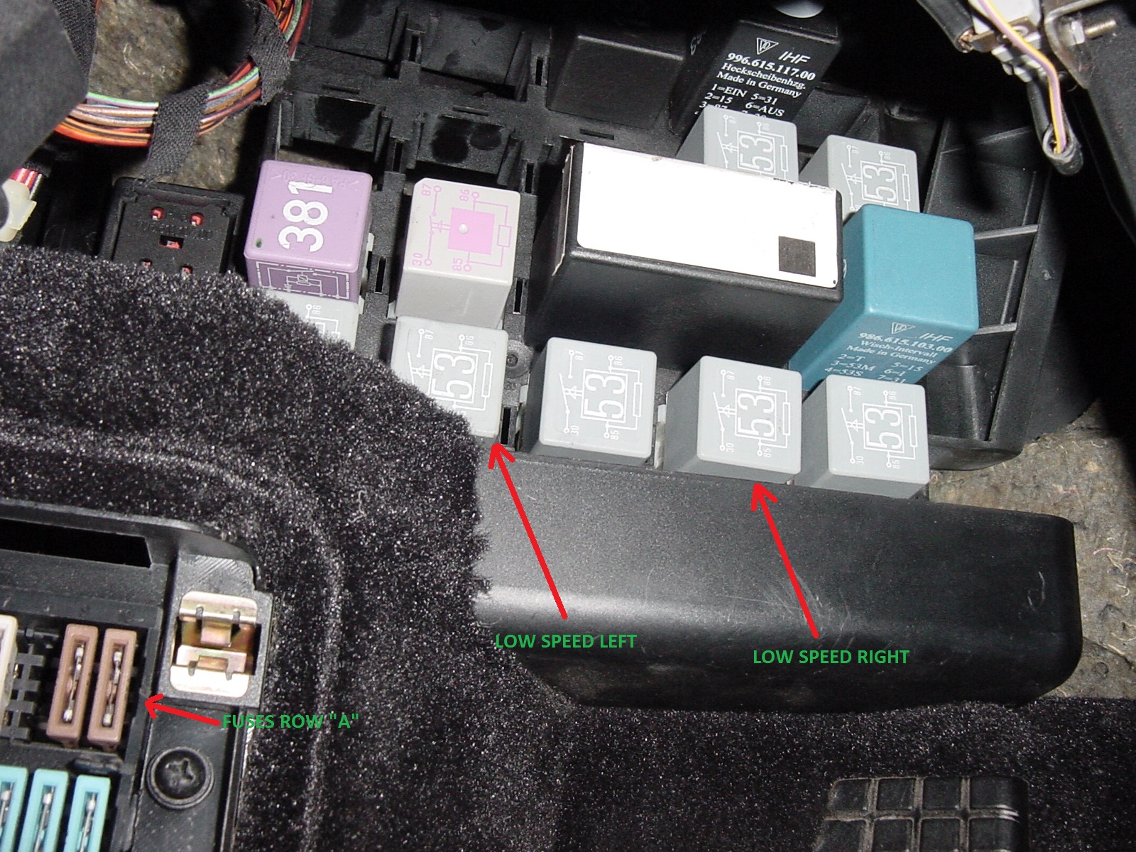
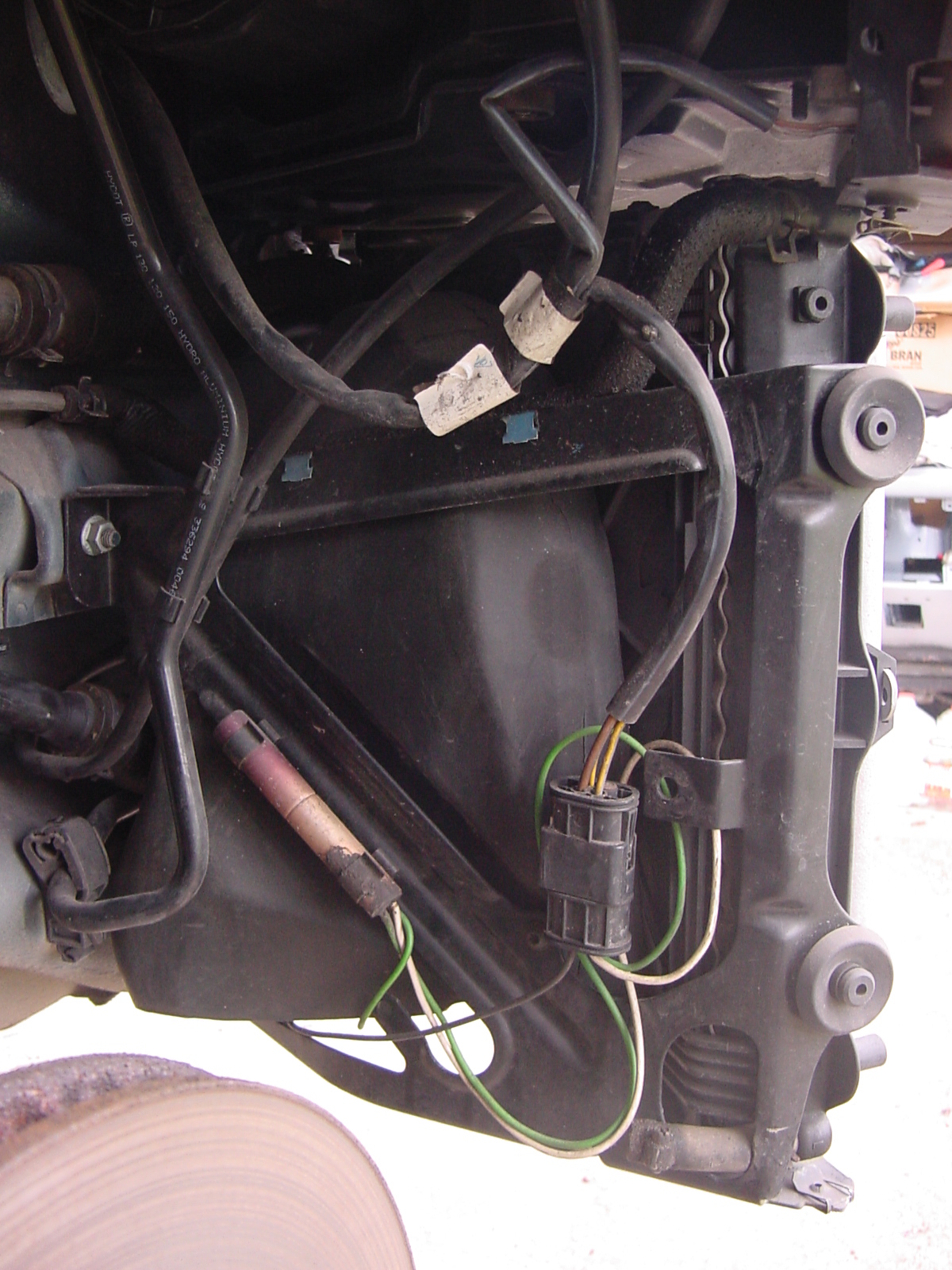
Frank: Is it possible that It may have been that way before you repaired the heater box foam, but may not have been aware of it? The fans and the two speeds are controlled by four relays (two for each fan, with each of the two sets having a low speed and a high speed) and two ballast resistors (one on each side). Since the fans are working (even though it's only on the high speed), it's not the fan motors and not the fuses. If you want to double check the fuses, they are C8 (radiator fan right) and C10 (radiator fan left). Both are 40 amp fuses. The ballast resistors' ceramic coating frequently crack because they get hot and are then sometimes splashed by cold water (as when you go over a puddle). The relay tray is located on the left kick panel, to the left of, and below the level of your left knee as you sit in the driver's seat. Here is a photo showing the location of the relays and the fuses (click on it for a good look): For reference to locate the relay tray, you can just see the top of the dead pedal in the bottom right corner. The four relays are in the lowest visible position when the fuse panel cover is still on (there is another row of relay receptacles below the visible row, but no relays installed in that row). The left low speed is position 19 in the relay tray, the right low speed is position 21 in the relay tray. Fuse Row C is two rows below row A, and position "10" is closest to the side shown by the fuse arrow. To test whether your resistors are bad (and thus not causing the fans to go on low speed), with the engine running and the engine temp below 206 degrees (e.g., engine cold), put your finger on relay 19 and then press the snowflake button on and off to turn on your a/c on and off. You should be able to feel (and hear) the relay clicking. Repeat with relay 21. If the relay clicks and the low speed fan does not go on, then your resistor is the most likely culprit. If the relay does not click, then the relay itself may be faulty, or there is a problem with the wiring or fuse. Again, if the high speed fan is running, it's not the fuse. The resistor is part number 996.616.101.00 although there may be a TSB with an updated part number for a new design resistor pack. Here is a photo of what the resistor looks like on the right side and its location behind the fan housing, near the frame rail: Note that you will have to remove the front of the wheel well liner to access it for viewing and replacement. Keep us posted with what you find. Regards, Maurice.

-
Steering wheels shakes when braking
1schoir replied to gregthiara's topic in 996 TT, 996 TT S, 996 GT2
Greg: Great that you finally got it solved! Thanks for posting the final solution. It is sure to help future posters. Regards, Maurice. -
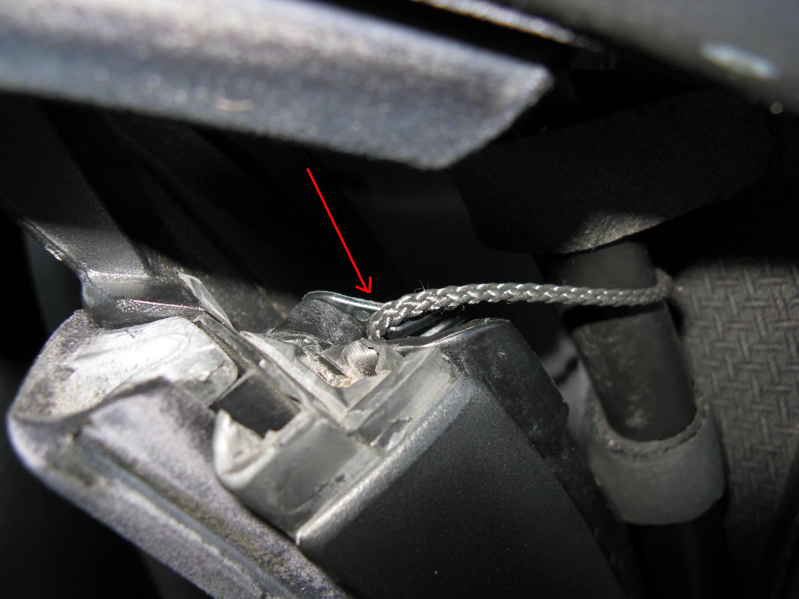
tychen: If the problem you describe is only happening when you pull on the outer handle AND the window does not go back up when the door is wide open, it's almost certainly the microswitch that is behind the outside door handle. There are two others in each door (one behind the inner door handle and one inside the door lock assembly), but those would cause the other symptoms I have mentioned. Here is a photo of the the outside door handle microswitch and its location (click on the photo to blow it up): The red arrow points to the microswitch, and you can see the small silver arm of the microswitch directly on the top of it, The green arrow points to the small lever that is attached to the outside door handle and that is what presses on the silver arm, which in turn depresses the tiny little black switch. Note that the photo is from a '97 Boxster, but it should be similar. There are DIY instructions on this site for removing the door panels of a 996/997. Regards, Maurice.
-
me neither. but read the TSB 3701 The reason for this is the adaptation of the torque converter lockup clutch in the Tiptronic control unit. If the car is driven in a restrained manner or is frequently driven in stop-and-go traffic, the Tiptronic control module adapts itself to unfavourable values that cause the grinding/rattling noises. The "fix" is to install a new Tiptronic control unit with modified software. The newer control module has the part number 996.618.180.04 (or greater). The latest part number 996.618.180.07 or newer. This TCU ensures that it never learns this 'bad behaviour'. The other cheaper route is to reflash TCU and drive more aggressively... Dealer used a PIWIS. Because I did the diagnosis - tech did the reset for free, and bought me an ice tea too :) Regards, Maurice.
-
William: If you can't find the little wrench that came with the tool kit, you can get a small socket set at Sears. All you really need is a 5mm socket and a short extension, and it has to have small "shoulders" so that it fits in the hole. A 1/4 inch drive set should fit with no problem, and it will lessen the chance that you will round off the "bolt" head. You can get a complete small set of these 1/4 inch sockets, complete with ratchet and small extension for less than $20 at Sears (item # 934861), here: http://www.sears.com...0&prop17=934861 Also, make sure that you are going into the correct rubber-flap covered hole as there are a few in that area. If you look closely at the photo in the manual, you can't miss. Regards, Maurice.
-
Spark Plug Tube replacement
1schoir replied to TomCat's topic in 996 Series (Carrera, Carrera 4, Carrera 4S, Targa)
TomCat: Here is a set of instructions on Pedro's Garage Web Site: http://www.pedrosgarage.com/Site/DIY_Projects.html Regards, Maurice. -
Painting a new hood (bonnet)
1schoir replied to mreynol5's topic in 987-1 Boxster Convertible Top Issues and Solutions
mreynol5: 1. Repriming the hood with the same primer color as what is underneath the color coat/clear coat on your old hood and on your dented bumper is the best bet, as that will yield a more uniform final color coat that is more likely to match the rest of the car. After scuffing it with 320, wet sand the existing primer with 400 and shoot the new primer on, following the paint manufacturer's recommendations (usually 2 or 3 medium wet coats). 2. A heat gun from underneath, combined with an object similar in contour to the inside of the bumper surface where the dent is located should pop it into place nicely. Don't overheat the spot. 3. 800 grit wet sand is ideal for final spraying prior to initial base coat and for sanding in between clear coats. Using a primer with an already mixed-in flex agent will give you the most durable paint film, as long as you mix some flex agent into the base coat and color coat. That will minimize rock chips and the spider cracks that usually result from other cars' bumpers tapping your bumper. Sherwin Williams' SpectraPrime primer surfacer is one such primer which yields excellent results. It comes in about 8 different colors for the primer, so you should be able to match the factory primer color. Other paint manufacturers make similar primers. Regards, Maurice. -
99 3.4 Overheating
1schoir replied to darrinsmith's topic in 996 Series (Carrera, Carrera 4, Carrera 4S, Targa)
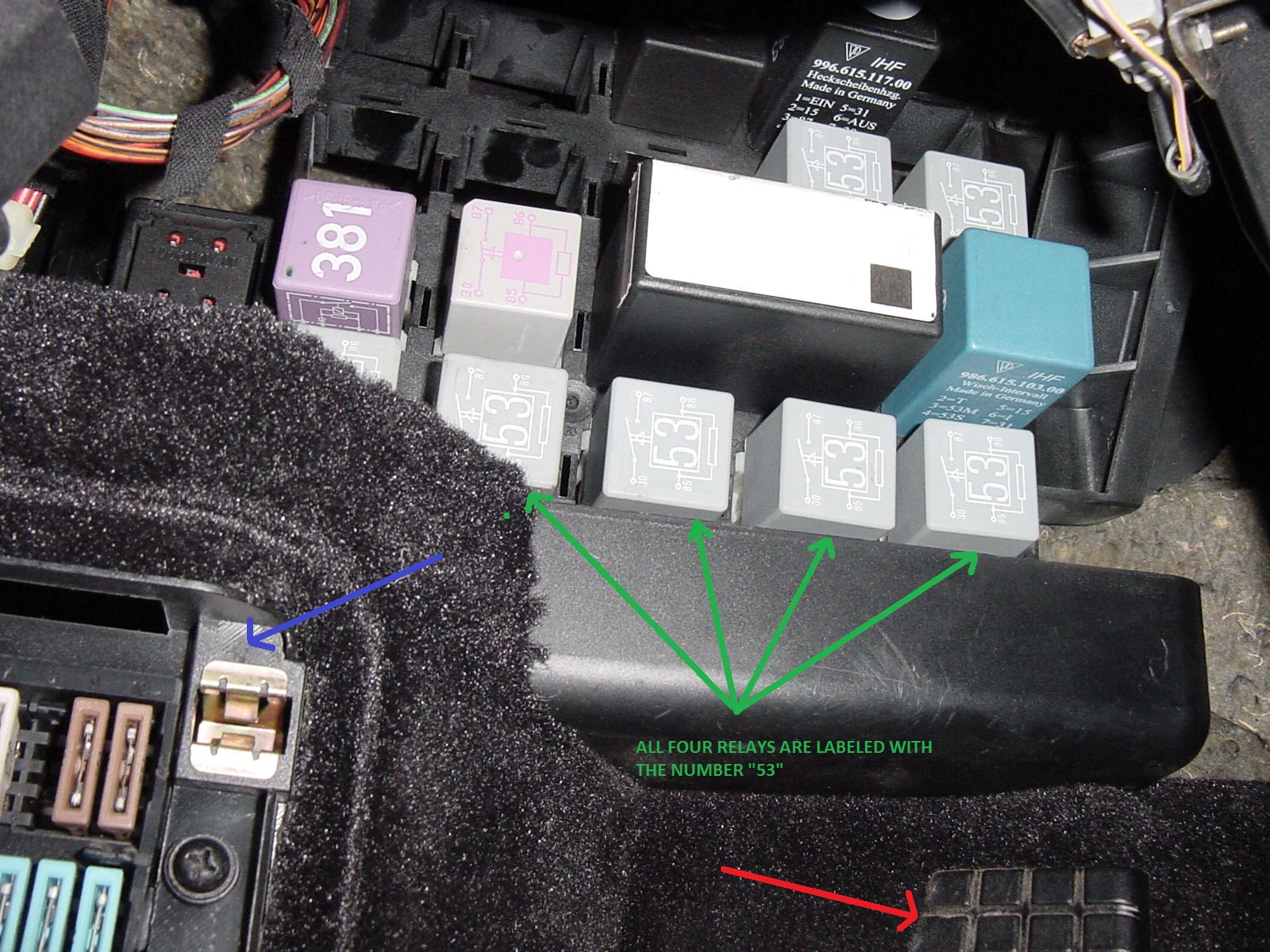
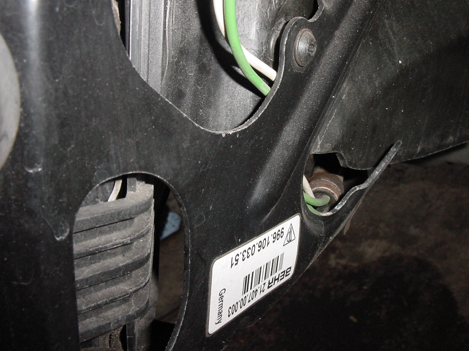
Interesting you say that because mine recently starts to creep up but only if the a/c is in the off mode but if i turn the a/c on then it brings it down. Where is the low speed fan or relay at? twcj: (Note that the following is from a 986 Boxster, but it should give you an idea of what you are dealing with). There is one fan behind each radiator, and it runs at either a high speed or a low speed, depending on coolant temperature and/or whether the A/C is switched on or not. The two speeds are achieved by means of relays, four of them to be exact (two for each side, one high, one low), in conjunction with one ballast resistor on each side, mounted on or near the frame rail, further to the rear than the fans. The relays are located on the bottom row of the relay tray (there is a row below that one, but it's "unoccupied"), which is mounted directly above the fuse panel, high on the kick panel by your left calf as you sit in the driver's seat. Here is a photo of the relays and their location: The red arrow points to the top of the "dead pedal", the blue arrow points to the top right of the fuse panel, and the four green arrows point to the fan relays. Note that the number "53" is washed out in the photo, but it should be on your relays. The resistors get hot and when they get splashed with cold water or rain, they crack internally and go bad. Here is the ballast resistor (at the end of the green and white wires): Here is a closeup of what it looks like: There is a way to jump the relays so that you can isolate the problem, and it was discussed on another forum. If I find the link, I'll post it here. Regards, Maurice.
-
Ahsai: Driving around with the bleeder valve open will usually do it. Just make sure that you monitor it closely and you should be golden! Regards, Maurice.
-
Thanks for the reply and that's exactly what I plan to do to finish the job. Ahsai: +1 on the over-torquing. With respect to the refilling of the coolant, you may have to use a vacuum device if you end up with any air pockets. You have the fact that you have only drained a little more than a gallon of coolant, so you may get away with either no or very little "burping". Regards, Maurice.
-
987 Water & Electric Problems
1schoir replied to nh1708's topic in 987-1 Series (Boxster, Boxster S)
nh: I'm guessing that one of your plastic ball cups (on the end of the front pushrods) popped off or broke apart, then the continuing operation of the top caused the newly dangling pushrod to dig into the foam drain tray, thereby ripping or tearing a hole in the foam drain tray, and that resulted (the next time it rained or you washed the car) in water getting into the cabin (at the floorboard, behind the driver's seat or both seats) thereby frying your central alarm control unit. The wet alarm control unit will cause the exact symptoms that you have described (among others). If the tear/rip is not too bad, you can seal it up effectively with a black adhesive sealant. Permatex makes a really good one for that application. To open the top and clamshell manually, follow the instructions under the heading "Your Top is Stuck in the Closed Position", here : http://sites.google.com/site/mikefocke2/thetop-itsmaintaince%26replacement Regards, Maurice. -
Oil filler tube/hose replacement Boxster 00
1schoir replied to 59caddy's topic in 986 Series (Boxster, Boxster S)
Dale: The fact that you are getting a change in the idle when you move around the oil fill tube (after getting an 1126 code), is a good indication that there is a leak in that area. You can further confirm it by spraying some carb cleaner (Gumout) at the joint and seeing if the idle rises. That will indicate that the extra "fuel" is getting sucked in by the vacuum leak and will help you pinpoint the source of the leak. BE VERY CAREFUL with the carb cleaner as it is flammable! Regards, Maurice. -
My roof won't go down
1schoir replied to junielomo's topic in 987-1 Boxster Convertible Top Issues and Solutions
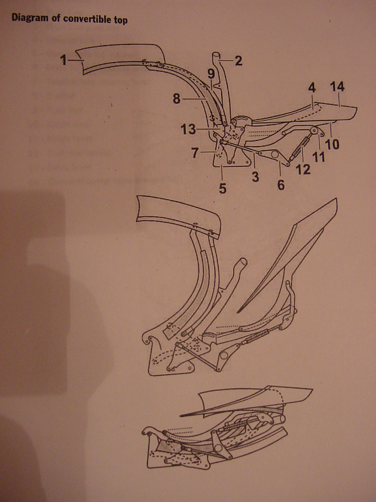
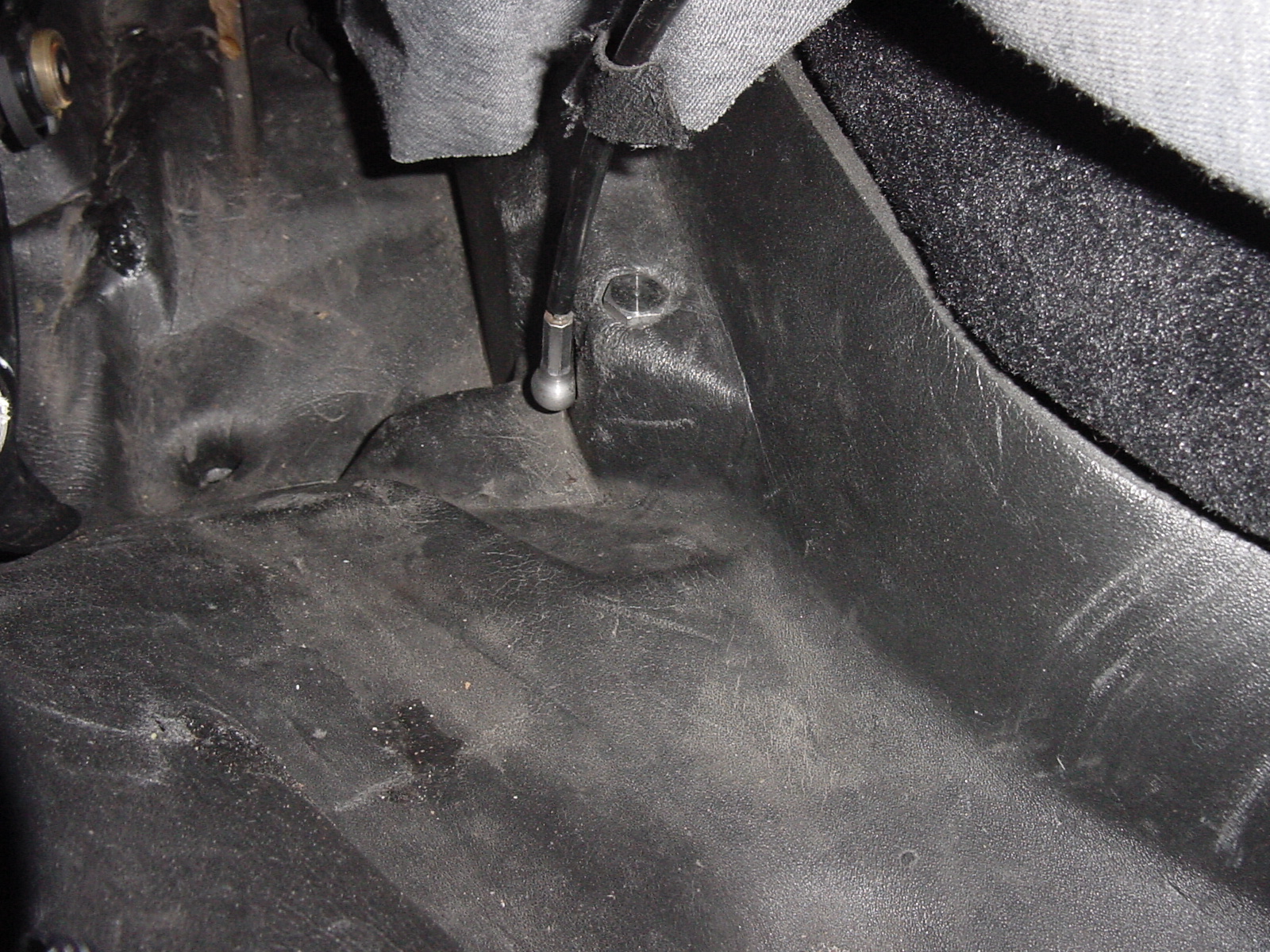
Junie: You have a couple of different issues here, the worst of which is the water intrusion problem. From what you have described, my guess is that both of your plastic ball cups have either popped off or broken apart at the front pusrods...by continuing to operate the top mechanism, the then dangling pushrods (which are attached on the opposite end to the front of the V-levers) promptly dug into the foam drain trays... thereby ripping or tearing a hole into them ... thereby allowing rain water to intrude into the cabin's floorpan...whereupon the water finds its way under the seats...which then will promptly fry your central alarm computer. Since you said "OPC", I'm assuming you are in the UK, so I'm not sure whether your Boxster has a central alarm computer. On U.S. cars it's under the driver's side (left side) seat. If you get to the central alarm computer early enough, you can take it apart and dry it and thereby save about $1k to $2K. You can rinse it with a contact cleaner and dry it before the contacts start corroding. Since it's a good bet that your plastic ball cups have broken up or popped off, the canvas part of the top can be operated manually (after you have moved the clamshell up and back to the 45 degree position). To move the clamshell manually, you must disconnect the black "hydraulic" pushrods, as follows: First, unlatch the latch of the convertible top at the top center of the windshield frame. To get the top to open manually, you must disconnect the white (or red if yours are original and have never been replaced) plastic cups at the base of the B-Pillar and the black hydraulic pushrods where they connect to the V-levers). (Since your ball cups are not connected, skip this step). Disconnecting the white (or red) plastic cups will allow you to operate the convertible top manually. Disconnecting the black hydraulic pushrods will allow you to operate the clamshell manually. Here is a diagram of the mechanism, which should help you orient yourself as to what you are looking for (click on the diagram for a better look): The V-lever is part #6, the black hydraulic pushrod is part #12, and the white (or red) plastic cup is located on the forward end of part #3. Part #14 is the clamshell, and Part #1 is the canvas top. To have a better chance to see the parts that must be disconnected, you will have to pull aside the (vinyl) rain curtain. That curtain is loosely held in place by yet another cable that is located at the rearmost corners of the (carpet-covered) engine compartment lid (on the car body, not on the lid). That cable is held on to a small metal ball and you must pry it apart from that metal ball. Here is a photo of the flexible cable that leads to the metal ball (hidden under the metal cup at the bottom of the cable) at the side of the curtain: That particular connection is easy to separate, unlike the black hydraulic pushrod. Once you have the curtain's cable separated, you may also have to remove the black plastic cosmetic covers that are simply clipped onto the arms that support the clamshell (those arms are part #10 in the diagram, and extend from where it is numbered all the way to the front towards part #3 in the diagram). Then you will have to reach between the roll bar hoops, or possibly reach through them, to get at the connection of the "hydraulic" push rod to the V-lever. That connection is a real bear, so you will have to apply a great deal of pressure to separate it. Be careful not to hurt yourself there, but you just have to get the connection apart, again with the red plastic capped tool in the tool kit, a fat screwdriver or, preferably an angled screwdriver-type pry bar. I have also had success using a non-automotive tool called a cat's claw, which is usually used to pull nails. If you cannot separate the black pushrods at their ball cup end, follow the pushrods to their opposite end, where they terminate in a small perpendicular rod that is routed through the body-colored clamshell support arm. At that point, on the inboard side of the support arm, you will see a small clip that you can push off before you can push the small rod outboard so as to detach the black pushrod from the support arm. Once you have the black hydraulic pushrods disconnected you will be able to manually operate the clamshell, just like the disconnected canvas top. Once you have the various parts disconnected, DO NOT press the dashboard switch without CAREFULLY marking (and photographing) the position of the V-levers relative to the sides of the body that they are mounted on. Otherwise, it will be much more difficult to re-sychronize the V-levers (part # 6 in diagram). Also, be very careful if you decide to operate your top manually because the push rod arms (part #3 ins dagram) that are normally connected to the steel balls at the base of the B-pillars will be dangling from the V-levers. When they are dangling and you move the convertible top V-levers, those push rod arms can dig into the foam liner and tear it, which will cause leaks into the cabin later on. Those push rod arms can also dig in and prevent the V-levers from turning. (This advice may be too late in your case, but it bears repeating so that you can be aware of the consequences). Regards, Maurice.
-
Roof won't open even if everything seems to be normal
1schoir replied to pavlin's topic in 986 Series (Boxster, Boxster S)
Pavlin: There are a few possible causes, which can be narrowed down if you can give a few more details. When you press the convertible top button (with the dashboard lights on and/or headlights on), do the lights dim? If so, that will eliminate three of the possible causes and leave the "over-rotation" of the V-levers as the most likely cause (because of the design of the "A-version" transmissions' half-moon gears). Also, check to see whether any of your plastic ball cups have popped off their steel balls at the base of the B-Pillar or whether they have broken apart. (less likely from your description thus far). Try the "dimming lights" test and report back. Regards, Maurice. -
Clickman is correct...The canvas from a four-bow top (i.e., OEM 2003-2004) will NOT fit on a three-bow frame (i.e, 1997-2002). Regards, Maurice.
-
Non-E-gas throttle cable adjustment
1schoir replied to flyingpenguin's topic in 986 Series (Boxster, Boxster S)
Checked routing of the throttle cable, and it is identical to the picture provided (Thanks kbrandsma!). What appears to be a adjustment screw in your picture above, is actually not, unless I am really missing something obvious here. Where to look for next? Joost Joost: Take a look at the point where the cable is attached and routed to the bottom outside surface of the rear firewall on the driver's side. There is a little curved black plastic cover installed on that little housing that you have to pull off to have a good look. Regards, Maurice. -
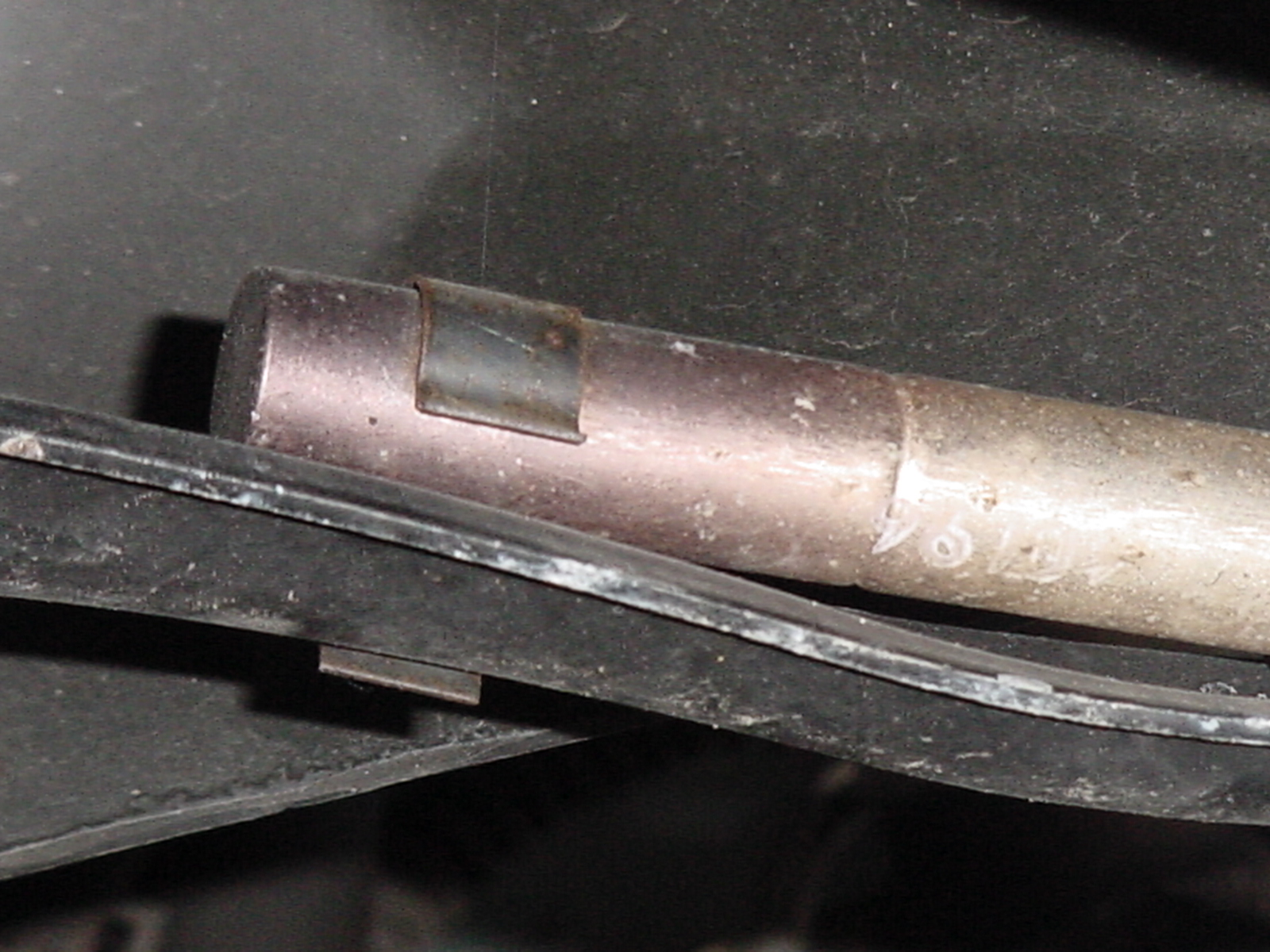
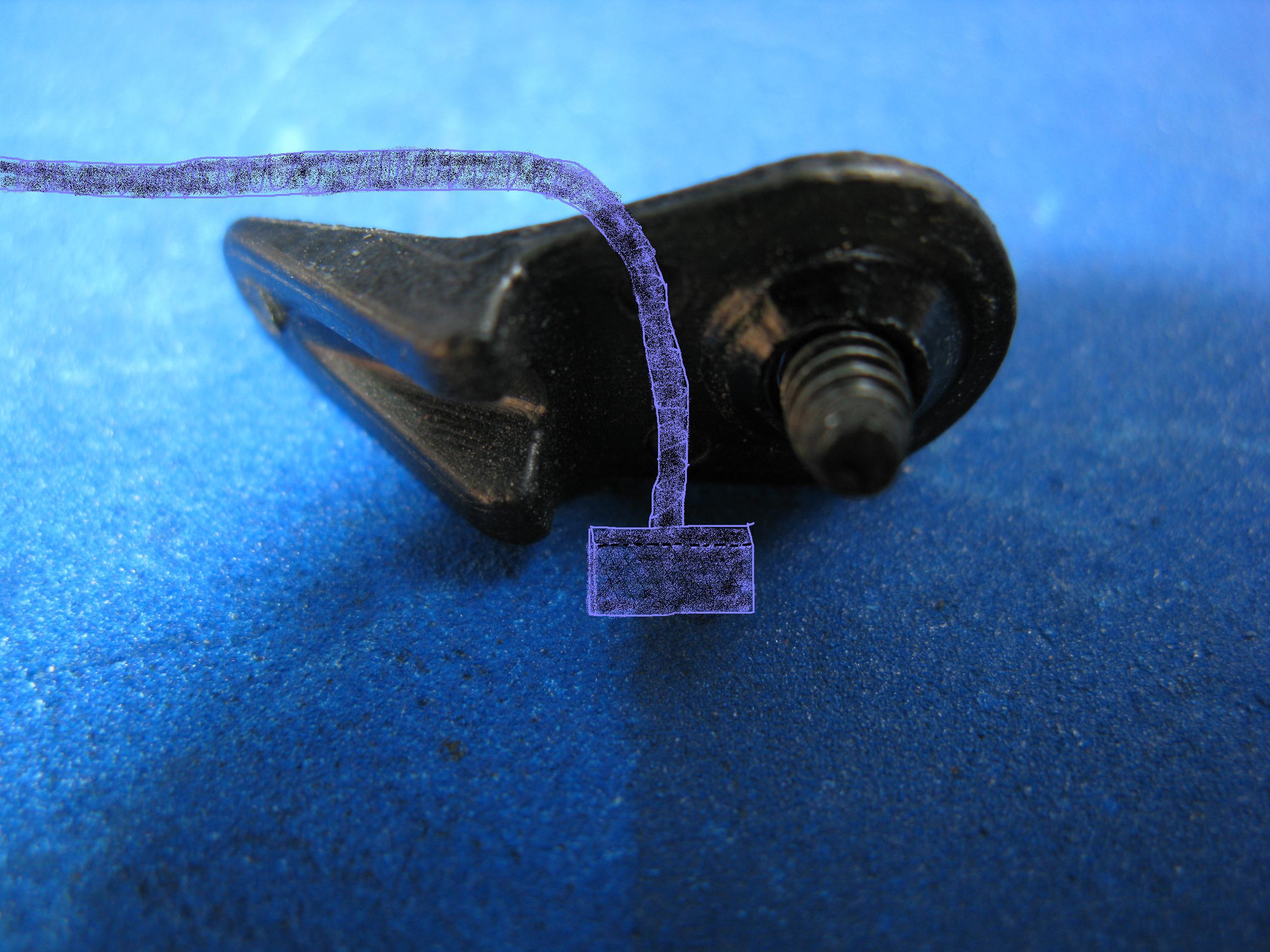
Got it, thanks. I did notice the following: the location where the shoestrings attach to the top (both sides), seems to be really "tired", may be ripped. But without another car without the problem sitting next to it is difficult to tell (need a reference). I will first experiment with the shoestrings, I will try to make a "fold" of about half an inch on each with a safety pin, and see how it does. Then I will continue to increase until the sides are "pulled enough" to fall in the groove. At that point I will sew the fold. PE: Here are a couple of photos of what the attachment is supposed to look like and how it's routed, (including one where I drew in the shoestring and its end): . . Also, don't ignore the fact that the elastic (in the middle part of this looped string, under the canvas) is there to maintain tension of the tension cables and to place a fold in the convertible top as it moves through its cycle. Be careful that the tension that occurs while the top is moving does not rip apart the looped strings or cause other damage. In other words, it may be a good idea to insert an elastic band section to sort of mimic the action of the original. Regards, Maurice.
-
PE: The part in the middle of the "fold placer" string is supposed to be elastic. That's the part that is in center of the roof, to which is attached the two "shoestrings", one left and one right, which are attached to one of the members of the convertible top frame. The "shoestrings" are not elastic. Regards, Maurice.
-
04 convertible TOP RETROFIT to 99 ?
1schoir replied to pk2's topic in 986 Series (Boxster, Boxster S)
PK: PM Sent. Regards, Maurice. -
P.E.: Here is the text of a DIY I wrote up about the "elastic ribbon", which Porsche calls a "fold placer". This might help you repair yours if a replacement is not immediately available: "...In 987's there is a different device holding the canvas in place, which we will call "looped strings", one on the left side and one on the right side. If either of the "looped strings" on your 987 are sticking out from where they exit the sides of the convertible top, and no longer under tension, you will have to replace the entire part that connects the two looped strings. The looped strings are attached to the convertible top frame by means of one fastening screw on each side. The overall part is called a "fold placer" and is part # 987 561 773 01. The fold placer costs about $69.00 as of this writing. The fold placer is actually two pieces of string that are connected to each other by being crimped on to a flexible elastic band in between them, from one side of the top to the other. The failure occurs when one of the crimped connections comes apart near the center of the top, and if that is the case, you will have to replace the complete "fold placer". It runs left to right through a canvas channel and you can guide the new part with a long piece of wire, then remove the wire and attach the strings with the fastening screw on each side. You will have to partially pull apart the convertible top liner in the area near the fastening screw to get at it. If you don't want to spend the $69.00, in some instances it may be possible to re-attach the looped strings to the center elastic band, but you will have to devise your own method of re-fastening the string to the elastic band after you remove the elastic band from its canvas channel...." If you want to read the whole DIY, go to Mike Focke's website, to investigate possible other causes, here: http://sites.google.com/site/mikefocke2/convertibletopedgedoesnotfallintoguidech Regards, Maurice.
-
Steering wheels shakes when braking
1schoir replied to gregthiara's topic in 996 TT, 996 TT S, 996 GT2
Greg: Your original post did not mention that the problem was happening before you had the brakes changed. If it was only a balancing issue or a problem with one of the rims, you would feel the shaking in the steering wheel WITHOUT having applied the brakes, most probably only at a certain speed range. You could eliminate that as a possibility by swapping the rims left to right for a few miles and then swapping them back. If you are not feeling any kind of pulsing or shudder from the brake pedal when you apply the brakes at 50 mph, then your problem probably lies elsewhere, perhaps in some component of the suspension such as the lower control arm or its bushings or the upper strut mount bearing. Regards, Maurice. -
Steering wheels shakes when braking
1schoir replied to gregthiara's topic in 996 TT, 996 TT S, 996 GT2
Steve: Lateral runout is the difference between the maximum and the minimum value that is recorded on a dial indicator gauge. You can measure the difference in those values by mounting the dial indicator gauge on a solid mounting surface with its tip perpendicular to the surface of the rotor, less than one inch from the outside circumference of the rotor. Then you spin the rotor and the gauge will record the maximum and the minimum distance from its tip to the surface because the distance of the surface will vary if the rotor is warped or if the thickness of the rotor is uneven. Think of it as the rotor being warped. If the lateral runout is too great (i.e., not within spec) that will cause pulsing or heavy shudder, depending on the severity of the runout or warping. If the rotor is thick enough and the runout is not excessive, the rotor can be turned on a lathe to eliminate the lateral runout or any uneven thickness around the rotor's face, again as long as you don't pass the minimum safe thickness. Turning rotors on a lathe used to be a lot more common in the old days. Nowadays, lots of the rotors, especially some of the aftermarket ones are just disposable. Also, if there is excessive corrosion on the surface of the wheel hub face, that will not allow the rotor to seat completely flush and square, and that will show up as runout as well. When you are mounting your wheels on the new rotors, don't use air tools and make sure that you torque the lug bolts by going across from one bolt hole to the bolt hole on the opposite side until you have all of them tightened to the proper torque value, preferably in two stages. Never torque the bolts in a circle. Regards, Maurice.