Welcome to RennTech.org Community, Guest
There are many great features available to you once you register at RennTech.org
You are free to view posts here, but you must log in to reply to existing posts, or to start your own new topic. Like most online communities, there are costs involved to maintain a site like this - so we encourage our members to subscribe or donate. All subscriptions and donations go to the costs operating and maintaining this site. We prefer that guests take part in our community and we offer a lot in return to those willing to join our corner of the Porsche world. This site is 99 percent member supported (less than 1 percent comes from advertising) - so please consider an annual subscription or donation to keep this site running.
Here are some of the features available - once you subscribe RennTech.org
- View Classified Ads
- DIY Tutorials
- Porsche TSB Listings (limited)
- VIN Decoder
- Special Offers
- Paint Codes
- Registry
- Videos System
- View Reviews
- and get rid of this welcome message
It takes just a few minutes to register, and it's quality Porsche information at a low cost.
Contributing Members also get these additional benefits:
(you become a Contributing Member by subscribing or donating money to the operation of this site)
- No ads - advertisements are removed
- Access the Contributors Only Forum
- Contributing Members Only Downloads
- Send attachments with PMs
- All image/file storage limits are substantially increased for all Contributing Members
- Option Codes Lookup
- VIN Option Lookups (limited)
Leaderboard


Popular Content
Showing content with the highest reputation since 07/14/2025 in Tutorials
-
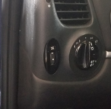 Rotary Switch to Manually Turn on the Cooling Fans Porsche 996/986 So the rotary switch has a fan symbol that lights up the same colour as the rest of the buttons in the car when the headlights are turned on. To turn on the low speed fans, rotate the dial up and the symbol lights up blue. Turn it down for the high speed (and the engine fan as well) and it turns red. The automatic function of the fans is not affected by this at all. In fact, the indicator lights will turn on when the car switches the fans on, so you can tell when the high or low speeds are on, which is cool. So the function of the rotary switch will be: -when at rest and headlights/parking lights are not on, fans are not on and the indicator light is not on. -when the dial is turned up, low speed fans are on and the indicator light illuminates blue. -when the dial is turned down, the high speed fans are on along with the engine bay fan and the indicator light illuminates red. -when the headlights/parking lights are on, the indicator lights orange. We will need 1 RGB LED, 1 diode, 1 resistor of 500 ohms, 1 resistor of 1000 ohms, 1 resistor of 5000 ohm (this may be different depending on the LED you use) Here is the wiring diagram that we will follow to make this work. First you need the headlight level switch. It was available only on the 996.1 cars and is part number: 996 613 230 01 You need to disassemble it, as all the circuitry inside will be replaced, and the headlight symbol removed. Remove the circuit board now, as it will be replaced with one we will make from scratch. Remove the LED as well and all wiring inside. Now you need to make a new circuit board to replace the old one. You need to visit an electronics store and get Ferric Chloride and copper clad board. Cut a piece of board to match the size of the old circuit board. Cut it roughly with a saw and then use a file to get it down to exactly the shape and size you need. Peel off the protective film and then lightly sand off the bluish film off the board until you have only copper exposed. Now you need to draw on the circuit onto the copper with a sharpie. I did it backwards, but it is soo much easier if you sand off the blue film and then draw the circuit. The chip will now go into the Ferric Chloride. The liquid will eat away all of the copper except for the parts you drew in sharpie, as the liquid does not react with it, leaving the copper underneath protected. When you take it out of the Ferric Chloride, you will have your chip. Clean off the sharpie with rubbing alcohol. Now you will drill 3 small holes in the bottom of the chip for wires to attach to. You will need to solder in bare solid wire into each of the holes. One contact will be for high speed, one for low speed and one for ground. Here you see the chip in place with the wires leading out of it. Each wire will need to be soldered onto a contact in the switch that leads to a pin. Now for the LED. You need a frosted 5mm tri colour RGB LED with a common cathode. The ground for the LED will go to pin 4 in the switch - same as the grounds for the high and low speed for the fans. The lead for the green will go to the 3rd pin. There is not enough pins for everything, so you will need to add more. I did this by putting a noche in the base of the switch to allow a couple wires to run out of the switch to another connector. I just picked up a male/female 2 pin connector from ebay like the one below. You will need resistors for these LEDs. Green is much stronger than red, so I used a 500 ohm resistor in series for the red LED, and 5000 ohm resistor in series for the green LED. 1000for the blue. You will need to test the light intensity and how the colours mix to get you the orange you need using different strengths of resistors to match the rest of your buttons. There is not much room inside the switch, so I placed my resistors and the diode outside the switch, which you can see here. Next is to make the fan symbol. Sand off the headlight symbol from the indicator piece. I had a tiny fan laser cut by a shop for me onto vinyl, which I then placed on the piece and painted black. Removed the vinyl, and now there is a perfect symbol of a fan that the LEDs will illuminate. Place back in the switch and now put it all back together. Switch is done. Now to wire everything up to the switch. The diode has to go where you see it in the diagram. It allows current only in one direction. Again, there is no room for it in the switch, so I have it in the wiring outside the switch. The diode will allow current to flow from the power supply for green LED to the red LED (this will make orange). You may need to test different resistor values to get the right colour of orange. Now to make it all work. We will need four 12v relays. I installed all 4 relays in the relay tray above the fuse box to make it look as OEM as possible. But they could go anywhere. You will need 4 relay plug with the metal connectors if you do what I did. Part number is 928 610 511 00. You need to locate the 2 low speed fan relays and the 2 high speed. The low speed relays are numbers 19 and 21, while the high speed relays are 20 and 22. Disconnect the battery in the car. First remove the fuse box panel. It is held on by 4 screws. You can then just pull it out. The relay box is above it. It is best to remove the relay box. It is held in place with a single nut, and clipped in on the opposite end. Flip the relay tray around so you have access to the back. I removed plugs that were in my way. Now use the wiring diagram from earlier to make the wiring connections you need. The proper routing and connections of the new wiring is all there in the diagram. The relays labeled as normally open or normally closed are the new relays you are adding. The purpose of these relays is to turn on and off the appropriate LED colour to indicate whether high or low is on, and to turn off the orange (if headlights are switched on) when fans are in operation. If you want the engine bay fan to also turn on with the high speed fans, then you will need to run a wire splitting off from the wire runs from pin 85 from relay 22 all the way to the back behind the rear passenger. There is another relay box there. I removed the rear quarter interior panel to help with running the wire as well as the bonnet/engine cover release panel trim. But you don’t have to, just tuck the wire in. Remove the carpet in the back to expose the relay box. It is on the right and is held in place with a nut in the centre and 2 screws on the right. You can see the wire I ran from the front. Flip it over and find relay number 8. You want to tap into pin 85 of that relay. Put it all back together. Now wire up the switch. The wire from pin 85 from relay 22 goes to pin 1 of your plug for the switch. The wire from pin 85 from relay 21 goes to pin 2. The wire from pin 87a from the normally closed low speed relay (see diagram) goes to pin 3. The wire from pin 87 from the normally open low speed relay (see diagram) goes to the connector you added to the switch - green wire The wire from pin 87 from the normally open high speed relay (see diagram) goes to the connector you added to the switch - red wire From the switch, we have a ground wire. This can go to any ground point in the dash. I found a spot close to where the switch goes and grounded it there. There is one last wire, and this is to get power to the red/green LED when the headlights are on. You can wire this to any switch in the car that illuminates. I took power for this from the intermittent wiper in the dash for power. Now with everything wired up, this should work. With the car on, but no headlights and the switch is at rest, there should be nothing. When the headlights are turned on, you should have the fan symbol light up in orange. Turn on the high speed fans, and you should have the engine fan and the 2 front fans on and the symbol should be red. On low speed, only the 2 front fans will be on at low speed and the symbol should light up in blue. The car will still turn on the fans automatically, and when it does, the fan symbol will also light up to let you know the car has turned on the fans at either high or low.1 point
 -
Today I did front final drive gear oil change. This DIY will show you how I did it. Since I had a hard time to access the drain plug, I removed fill plug and used a pump to suck out the final drive oil. Worked really well, and helped avoid messy drain, which puts oil onto the lower axle carrier frame too. FSM calls for change quantity of 0.42L, and I managed to remove about that much from the drive, so I feel confident I got it all. Used empty oil can go suck old oil into it, and another empty oil can to put same amount of new oil it, making sure I fill with what I removed. I actually filled the new oil can with maybe 1/4" more oil, to accommodate for some oil that pump cannot take out of can, and some oil left in tubing. Oil used for change: Mobil Delvac 1 full synthetic gear oil 75W-90 (direct cross reference to Shell TF0951 - factory fill oil) Oil refill quantity: 0.42L (bit less than half a quart) New fill plug part number: N 902 818 02 Fill plug tighten torque: 25.8 ft/lbs Fill plug removal tool: ratchet, extensions (at least 6"), 5mm hex socket, shop towels Look at this DIY before you do the change. Make sure you have all materials and time to do it. Expect about an hour to hour and a half to complete. Let us know if you have comments. Thank you.1 point
-
This DIY tutorial covers how to remove the intake manifold on the 3.6L V6 Cayenne. Removing the intake manifold gives you access to several parts of the engine that you may need to service. Disclaimer: Perform at your own risk. This is for reference only, I am not responsible for any damage/injuries that may occur from this procedure. Please do not attempt if you are not comfortable with doing work on your car or working around the fuel system. Work in a well ventilated area as you will be releasing a small amount of gas and fumes. Difficulty: 5/10 Estimated Time: ~2 hours If you’re getting a Durametric error code P0674, you likely have a bad PCV valve that needs to be replaced. An easy way to test a bad PCV valve is to unscrew the oil fill cap on the engine while it is idling. If you feel suction on the cap and/or the idle fluctuates once the cap is removed then your PCV valve is bad. The PCV valve is built into the valve cover so your options are to buy a whole new valve cover assembly (95510513500- ~$347) or buy just the PCV membrane (aftermarket $20-25) and replace it in your existing valve cover. To get access to the valve cover, you will need to follow this DIY article to remove the intake manifold first. Other reasons to remove the intake manifold are to service your fuel injectors or to make it much easier to replace the thermostat. The thermostat can be changed without removing the intake manifold (I did it twice), however you basically need to be a contortionist to reach the bolts to remove housing and you will scrape some knuckles along the way. Tools Needed: -Flathead screwdriver -Assortment of torx bits (T20, T25, T30, 6” long T30) -Pliers -Torque Wrench -3/8” ratchet set with various extensions and a universal joint -1 1/16” Deep socket -10mm Triple Square Spline Bit -Crescent Wrench -9/16” Open End Wrench -Dental pick Parts Needed: -Brake Booster Vacuum Hose- 95535557941 (your existing hose is probably brittle and will likely crack from removing it, I recommend getting a new one) -Lower Fuel Injector Seal Kit (3X) - 95511091000 (existing seals may be brittle and once you have removed the intake manifold, they may not seal properly upon reinstallation, I recommend getting new ones, need 3 sets) Procedure: First start by removing the plastic covers surrounding the engine. Using a flathead screwdriver, remove the quarter turn plastic trim fasteners. Rotate them in either direction by 90 degrees and pop them out. Be ready to catch them as sometimes they like to jump out. Next you will need to remove the 2 torx screws on either side of the engine cover with a T25 bit and the screw under the windshield washer reservoir cap with a T20 bit. Remove the oil fill cap and front engine cover by pulling straight up. They are held on by friction rings around a stud so pulling straight up will release it. Now that you have the covers removed, it’s time to remove the intake filter box and intake piping. Using your T25 torx bit, rotate the 2 screws until the dot on the screwhead lines up with the lower indication on the filter cover. Now gently use your pliers to pull them straight out. With your flathead screwdriver, pop up the two clips to release the filter housing. Pivot the filter house towards the passenger side of the car and remove it. Remove the engine air filter as well. Next, remove the wiring harness from the MAF sensor located in the middle of the intake piping. Loosen the clamp around the intake piping on the throttle body and gently work the intake piping back and forth until it releases from the throttle body. Remove the top bolt on the engine lift bracket and loosen the lower bolt with your M10 triple square bit. Then pivot the bracket towards the front of the car. Remove the bolt next to the throttle body with your M10 triple square bit. Then unplug the wire harness from the throttle body. Remove the top bolt from the bracket on the passenger side of the engine with your M10 triple square bit. Remove the vacuum lines from the intake manifold on the passenger side of the engine. One hose requires pliers to open the hose clamp, the other can be removed by hand if you squeeze the lock ring around the hose to release it. Next, from the passenger side, reach your hand around to the back side of the engine. There is a vacuum line that goes from the bottom surface of the intake manifold to the brake booster. You will need to pull the vacuum line fitting straight down to pop it out of the intake manifold. I don't have a good picture of it so here is a diagram of it. Pull down on the elbow fitting, not the hose. Also on the back side of the engine just behind the vacuum line you removed there is a bolt that needs to be removed using your M10 triple square bit. You are working blindly so locate the bolt first by feel and guide your bit to the bolt. Remove the 3 screws holding the actuator with a T25 torx bit. Slowly pull it straight out towards the front of the car. There is an actuator arm that attaches to a shaft on the passenger side of the part. Once you have enough clearance to reach your finger in there, you need to slide the arm off the shaft as you pull the entire actuator off. Then disconnect the vacuum hose from the actuator. Now pull the coolant hoses out of their holder in the intake manifold and push it towards the driver side of the car. There is a T25 torx screw that attaches this water hose bracket near the back of the intake manifold. The screw is facing up, so you need to use your T25 torx bit and get creative with removing that screw. I used a crescent wrench to turn the torx bit while holding the torx bit in place with my other hand. With the water hose bracket free, slide the water hose bracket towards the front of the car to release it from the intake manifold. This bracket has a keyhole slot that will release once it's slid forward. Remove the oil dipstick tube bracket with a T25 torx bit. Just push it out of the way once you remove the screw. With your long T30 torx bit, remove the bolt on the intake manifold that was under the actuator. Next, there are 3 blind holes on the driver side of the intake manifold. You need to use your long T30 torx bit to loosen the screws inside those holes. Those 3 screws are captive screws so they will not come out. There are 3 bolts below the intake runners. They need to be removed with your M10 triple square bit. This is where your universal joint will come in handy. The bolt near the rear of the engine required me to use my u-joint with various entensions to acess. At this point, you will hear gas leaking out. Since you have released the pressure from the lower fuel rail to the lower fuel injectors, the pressurized gas in the rail will leak out. Make sure you are working in a well ventilated area. From the driver side of the car, reach behind the engine to remove the wire harness from the fuel pressure sensor. Using your 1 1/16” deep socket, unscrew and remove the fuel pressure sensor. Using your 9/16” open wrench, unscrew the nut that connects the metal fuel line running from the lower fuel rail. The slimmer your wrench the better. My crescent wrench did not fit here. Now that the intake manifold is completely unbolted, you can start to wiggle it free. You will need to lift the manifold up from the passenger side and pivot it up towards the driver side. You will need to wiggle the lower fuel rail loose to release the metal fuel line you just unscrewed the nut from. It is a flare fitting that pushes into the upper fuel rail assembly. Be gentle here as you don’t want to bend the fuel rail. Once the metal fuel line is free from the upper assembly, you can remove the intake manifold as described above by lifting up from the passenger side first to pivot it off. At this point, you have access to the fuel injectors if you need to service them, the thermostat housing and the valve cover. Unbolting the valve cover is straight forward from here if you need to replace the PCV valve, etc. The fuel injector seal kit comes with a rubber o-ring, Teflon o-ring, Teflon sleeve and metal clip. At the bare minimum you should replace the rubber o-ring and Teflon o-ring. Use a dental pick to remove the old o-rings. These 2 parts are the wear surface when you remove/reinstall the intake manifold and are prone to fail if you re-use them. Trust me, I learned the hard way. To install the intake manifold, reverse the steps above. Take care in sliding the lower fuel rail back onto the lower fuel injectors and lining up the metal fuel line back into the flare fitting. I found it was easier to pull the lower fuel line out of the manifold to line the flare fitting up first, then pushing it into place in the intake manifold. You want to apply even pressure on the surface as you tighten all 7 of the bolts down on the driver side. Torque the 3 triple square bolts evenly to 6 ft lbs, torque angle 90 degrees, then a final torque of 22 ft lbs. The bolts holding the engine lift bracket are 17 ft lbs, the other triple square bolts holding the manifold on the head are 15 ft lbs. Once you get it all back together, turn the key to the ON then START position without your foot on the brake. This will run the fuel pumps to build pressure back up in the fuel rail. I removed the key and repeated 2-3 times to get the fuel pressure up. The first time you restart, it may take a couple seconds to fire up due to the fuel pressure needing to build back up. If you replaced your PCV valve, it may idle rough as the ECU needs to remap since it adapted to a leaking PCV valve over time. If you did not replace the fuel injector seals and smell gas/hear it leaking after shutting off the engine, then your seals failed and you need to repeat the procedure and replace those seals.1 point
-
I will be posting a starter repair/cleaning tutorial for the Porsche Cayenne. I bought a 2006 S a few months back and it had the startup whine that I believe is common to this vehicle. I have replaced the old starter with a Chinese $130 job, but I don't trust that the starter will last. I was amazed that no one had posted a DIY for this since the new Bosch starter is so **** expensive. As of right now I have most of the starter disassembled (which was not difficult except for one part that I can't figure out). As I clean and put back together I will post pics and advice. I found a few sites where you can get starter parts, mostly in Great Britain. I used a parts company called saverepair.com. Unfortunately, Bosch doesn't supply a lot of parts specific to this starter. The starter number is 0 001 125 025. Other good reference sites are aspwholesale.com, https://en.as-pl.com and this parts breakdown helped TREMENDOUSLY http://www.woodauto.com/Unit.aspx?Man=BOSCH&Ref=0001125025 (which wood auto was my second choice for parts but they cost a bit more.) What I could order from saverepair.com were these parts. bsx208-209 Bosch Starter Motor brushes 5.8 mm x 18mm x 14.6mm. 1 €3.60 €3.60 wsbu9016 Starter Bushing 10,08mm x 14,04mm x 9,90mm Rear bushing for Bosch,Front Bushing for Valeo D7E, and Centre for Ford Motorcraft. 1 €0.55 €0.55 wsbu9022 Starter Bushing 28,47mm x 32,30mm x 10,00mm. Front bushing used in Self-Supported Bosch starters. 1 €1.72 €1.72 wss0020 Starter Solenoid for Saab 9-3 Turbo 9-5 Turbo 900 9000 Opel Astra F Corsa A B Kadett E Vectra A B Lancia Fiat and more. 1 €18.00 €18.00 Pretty cheap parts as you can see. When I received the parts I was a bit concerned that the solenoid wouldn't work (I basically picked it by cross referencing starters that were close to the number range and had the same type of connectors). This solenoid is a bit larger than the old one, but the screw holes match up perfectly. I have never replaced bushings or brushes before, so this will also be an adventure I'm sure. On a side note, I REALLY wanted to replace the main bearings on the starter, but there are a few things I can't figure out. There is a part called the bendix that has the gear at the end that also holds the bearings. It is also attached to the stationary gear and a spiral gear shaft. I can't figure out how it all separates. If I did, I could just replace the entire bendix with the bearings on it. I'll see if I can attach a pick of what I'm talking about. If I can't get them separated I think it will be fine as the bearings still turn. I believe the major points of wear on the starter is the bushings. There is wiggle and play on the shafts on the bushings, which is probably why the starter was whining. Stay tuned! One more thought on removing the starter itself. There are write-ups for that so I won't delve, I will say, it is a relatively easy job of removing parts to get to it, but it does take a lot of time. I was able to remove the starter also without disconnecting coolant lines. I also added a pic of me after ripping the engine apart, with a much rewarded pipe blend called "quiet nights" (completely irrelevant to the post, ha!).1 point
-
About 3 weeks back I started getting a CEL with a Code 0335 Crankshaft Position Sensor "A" Circuit. Upper Limit Exceeded. After clearing the code it kept coming back within a day or two and the car stalled on two occasions. Based on research on the forums, this seemed very much in line with sensor failures on 955's and a DIY existed for these model years, but not the 957. My 957 now has around 120k miles, and the engine runs incredibly well, aside from this one recent anomaly. I ordered a replacement sensor, from Pelican Parts which arrived the next day (very impressive service) :lowdown: thanks Pelican Crankshaft Sensor Brand: Bosch Note: Engine Type: 4.8L 4806cc V8 (3.78x3.27; 96.0x83.0) (2008 Porsche Cayenne S Sport Utility) Part #: 0-261-210-292-INT As there was no info available on this DIY for a 957 so I'm hoping the following will help others get this done easily when needed, and in particular so you can save the 2 hours extra it took me to figure out where and how everything was located, as well as how to get to it. Which I did while I was waiting for the new part to arrive However once that research was done, the actual job of replacing the sensor took about 45 minutes. The main challenge is that the connector is difficult to access as it is behind and below the fuel pump on the right hand side as you face the front of the car. Even with an inspection scope it was difficult to locate. It was only once I looked from under the car that I could see where it was located. Also the connector plug is attached to a rectangular section of plastic tubing/conduit on the wiring harness, by a clip which is very rigid. After multiple attempts to release this clip it broke off. I think give the location it gets very hot and over the years becomes brittle. You should remove the engine compartment trim at the rear of the engine for better access. I also borrowed a few pics of an engine on the web to mark the location: I also found that removing the harness from the engine made it easier to get my hands around the connector to get the two ends separated. Once you have the old sensor disconnected, attach the new one and and tape the end of the new sensor tip with some painters tape just for protection and slowly lower it down into the engine compartment. It will end up either side of the primary cat where it is easily accessible from below. Also let the old sensor cable drop into the engine bay as you will then extract it from below. Now move to underneath the vehicle. I only needed to jack up the front left of the vehicle (jack stand + jack for extra safety). No wheels need to be removed. Do not jack up the car before dealing with the connector at the top of the engine bay as it will make it difficult to reach. Between the connector and the sensor, the cable is secured at 3 locations. See pictures below. The cable is pretty easy to remove and secure from below the vehicle and it can be seen and accessed without removing any of the under trays (depending on your level of flexibility). The lowest retaining clip is a push in type retaining clip where you simply press the cable into the tensioned clip. The two upper retaining clips are circular in shape and hinge open and closed. With a built of gentle persuasion you can pull them open and the cable comes out easily. I could not get the uppermost one in the pics but it is similar to the 2nd one shown in the pics. The sensor is held in place with a single torx T5 screw. Once you have the old sensor off you can pull it out and put it aside and attach the new one. I suggest attaching the sensor first and the attaching the cable to the retaining clips. Very rewarding and inexpensive fix, and everything is back to normal. No more codes and the car runs beautifully!1 point
-
My Porsche is a 1999 996 C2 Cabriolet. The convertible top compartment lid (the “lid”) is attached to the body via two hinges which each have two arms. The front arm on the left hinge was broken, so I replaced the entire hinge, as replacement arms are not available. Here is the step by step process of how I did it :(I had a bunch of great photos with this article, but for some reason they did not copy and paste with the article) (I'm what you might call "format impaired".) : Tools needed: Flat Head Screw Driver 10mm Box Wrench T-30 Torx Bit 13mm Socket Short Socket Extension Electrical Tape Parts Needed: Replacement Hinge Part #996-561-907-02 (Left side) Replacement Seal Part#996-561-904-00 (“Cabrio Plate” in Porsche terminology) 1. Open the top partially so that the top is open about half way and the lid is in the fully open position. 2. Disconnect the cables that keep the rear-most part of the top secure to the car. There is one cable per side. Push the cable inward (toward the center line of the car) to release it from the ball connection. Release both cables. 3. Let the top move forward toward the closed position and push the window section up and out of the way. 4. Use the flat-head screw driver to remove the 4 plugs that keep the rear carpet in place. Remove the carpet, starting at the top and working it around the trim. 5. Once the carpet is out, follow the lid stop light wire down and disconnect it. It simply unplugs. 6. Release the wire from fastening elements (Porsche terminology) on the rear arm of the left hinge. 7. Mark the location of both left and right hinges in relation to the lid, then use the 10mm wrench to remove the 2 nuts securing each hinge to the lid. Prior to removing any parts, cover the drain hole below the hinge with a paper towel to prevent any small bits from falling into it. Once broken loose, they can be turned by finger. (This is probably better done with the assistance of a helper to support the lid, but can be accomplished by one person working alone by removing the rear nuts first and supporting the lid in place with one hand while removing the front nut on each side with the other hand.) Remove the lid from the car by lifting it up off the hinge. 8. (For the left hinge, only.) Remove the plastic fasteners for the lid stop light wire from the hinge for reuse on the replacement hinge. These both just clip on and can be easily remove with needle nosed pliers. 9. Remove the additional flap for reuse with the replacement hinge. The flap is removed by pushing the locking lever forward, then pulling the flap backwards and pulling downwards out from the underside of the hinge top. 10. Undo the motor drive from the hinge rear arm by removing the 2 Torx screws with the T-30 Torx bit. 11. Disconnect the motor drive push rod from the front locking hook at the front of the hinge by releasing the small clip retaining it. It should come off by releasing the locking tab slightly and pushing down at the same time. 12. Remove the motor drive body from the body of the hinge by removing the 2 Torx screws with the T-30 Torx bit. It’s not necessary to remove the pin with the flat head slot on it in order to remove the motor drive from the hinge. It may take a little rocking, but the part should come right off without much effort. 13. To give more play in the hydraulic line to the motor drive to be able to get it well out of the way, with the flat head screwdriver release the tie securing the line to the bottom of the compartment. This just pops off and presses back onto a threaded retainer. 14. Move the motor drive out of the way and with the 13mm socket remove the 2 nuts and 1 bolt attaching the body of the hinge to the body of the car. The 2 nuts are clearly visible, but the bolt is concealed behind a plug in the trim piece covering the front of the hinge. To access the bolt, remove the plug with the flathead screwdriver. (Be careful not to drop the socket or the bolt behind the trim piece as fishing them back out may be a challenge.) Once the nuts and bolt are removed, the hinge can be gently removed from behind the trim piece by pulling up on the back of the hinge and rotating the entire hinge about 90 degrees counter clockwise and pulling up and back while gently prying up on the trim pice with the other hand. (This is probably the hardest part of the entire procedure.) 15. Adhere the seal to the back of the new hinge replicating the position of the old seal on the old hinge. Clean up around the openings in the body panel to remove debris left behind from the old seal. Remove the backing film from the seal before installing the hinge. Make sure the contact surfaces of the hinge and body are not adhered over by the seal. Installing the new hinge is the reverse of the removal procedure: Work the front of the hinge back behind the trim piece; Attach the hinge to the car body with the 2 13mm nuts and the 13mm bolt and torque to 7.5 ftlb.(I used the electrical tape to temporarily secure the bolt to the socket and the socket to the extension to ensure I didn’t drop either down behind the trim piece.); Attach the motor drive to the hinge body with the 2 long T-30 Torx screws and torque to 7.5 ftlb.; Attach the motor drive to the rear hinge arm with the 2 short T-30 Torx screws and torque to 7.5 ftlb.; Reconnect the motor drive pushrod to the lock hook at the front of the hinge with the small clip; Re-secure the hydraulic line tie in the bottom of the compartment; Attach the brake light wire fasteners to the rear arm of the new hinge; Reattach the additional flap by inserting it onto the pins on the underside of the hinge and pulling it forward then pulling the locking lever backward until it locks; Install the lid, leaving the 10 mm nuts slightly loose and press the stop light wire into the plastic fasteners and plug it back into the connection; Reinstall the carpet; Reattach the rear roof cables; Next align the lid, so it will close properly aligned with the body. Using the marks made at the beginning of the process should make this a bit easier.1 point
-
Posted this on the 986 forum, thought I'd share it here... here's the link to the 986forum.com post in case there might be any relevant discussions 986 forum DIY1 point
-
1.) Un-screw the one phillips head screw at top center of side air intake... 2.) The molded air duct and the intake grill are still attached by three delicate plastic tabs at the three points... The best way to remove this is gently insert your fingers through the grills into the intake at the points circled in red and gently try to free the tabs... All three points come forward towards you, but if one is stuck or gets caught it will break... 3.) Inside the drivers side air duct you will find a snorkle... The snorkle is added to most US cars for noise restrictions. Now this piece is attached by no screws or tabs, but it most likely will give you some troubles removing... The best way is to remove this, just grab a hold of the long snorkle (not the small dish on the end)... Now wiggle it from left to right and vice versa while pulling out towards you. This works, but might take a little effort. 4.) This is what the intake is going to look like after the snorkel is removed... Just carefully insert the three tabs back into their points... Make sure that all three are tightly in by pushing the airduct cover (not the grill)... Insert your 1 screw into top center of cover and you are done.1 point
-
Installing an MY02 Carrera C2 (Manual) Instrument Cluster in an MY03 Boxster (Manual) I have a few of general observations. First, I selected a Carrera C2 (manual transmission) instrument cluster because, having read through several threads on this forum, there didn’t appear to be any systems compatibility problems with the installation. For example, fuel gage problems with a C4 cluster (due to fuel tank design) or oil quantity/car leveling errors with a Turbo cluster (due to engine sump differences) were some of the problems to be avoided. Once the additional wire for the oil pressure gage is installed, the change over from Boxster cluster to Carrera cluster is truly “plug and play”. Second, it is essential to get a donor instrument cluster that is compatible with your car, in terms of original vs. “improved” cluster design. MY02 and subsequent 996 instrument clusters are improved. MY01 and subsequent 986 instrument clusters are improved. If you just have the hardware in hand, look at the color of the three plug receptacles on the back of the cluster. The original cluster has blue, white and black receptacles. The improved cluster has green, blue and gray receptacles. Third, there doesn’t seem to be a problem dealing with the MOST bus, or absence of the MOST bus. If the installation is done in a MOST bus equipped Boxster, the only anomaly will be the “Porsche Protected” display on the CDR23 radio. This is corrected using a re-coding routine by a PIWIS. If the Boxster being modified doesn’t have the MOST bus (pre-MY03), then entering the radio security code is the only step required after hooking up the battery at the end of the installation. Fourth, because my car is still under CPO warranty, I had my Porsche dealer install the Carrera oil pressure sensor. I didn’t want any arguments if, down the road, there were any problems with the lubrication system that could possibly be attributed to me working on the engine. Fifth, I sent my Carrera instrument cluster to an instrument shop to have the mileage reset to approximate the mileage I anticipated to be on the Boxster when I affected the change. The mileage is stored in the instrument cluster and can’t be reset using a PST2 or PIWIS. I got a receipt from the instrument shop indicating the mileage they reset the odometer to. When the dealer re-coded the radio, I had them verify the mileage on the Boxster odometer and the mileage on the Carrera odometer. The dealer put both mileages on the work order and made an entry on page 1 of the maintenance booklet. Sixth, I had about 7/8 of a tank of gas in the car. Some of the threads I had read suggested that there would be a problem with the fuel quantity indication if the instrument cluster was changed when there was less than 19 liters/5 U.S. gallons of fuel in the tank. After the change, the Carrera instrument cluster fuel gage indicated the same quantity as before, 7/8 of a tank. Due to the winter weather, I haven’t driven the car enough to require a re-fuelling. But, the gage does seem to work properly. Last, my MY03 (e-gas) base Boxster was delivered with cruise control. I had done the OBC/4 stalk “hack” earlier. All functions of the cruise control and OBC work. The OBC display is in the “improved” instrument cluster, dot matrix format. REQUIRED PARTS New/used Carrera instrument cluster appropriate for Boxster, for example: P/N 996.641.223.00.70C Pressure Sensor, Engine Oil: P/N 996.606.203.01 New/used Cover, Instruments, for example: P/N 996.552.059.02 EFM (black) – if you want to use a Carrera part, otherwise modify the existing Boxster instrument cluster surround. Wire Pin: VW P/N 000.979.010 Heat Shrink Tubing: Radio Shack P/N 278-1611 Quick Disconnects: Radio Shack P/N 64-3132 Hook Up Wire, Stranded 20 Gage: Radio Shack P/N 278-1225 Tie Wraps: Radio Shack P/N 278-1631A Most of the Radio Shack sourced parts are well in excess to your needs. But for about $7.00 total expenditure……… REQUIRED TOOLS Ohmmeter 10mm socket with ratchet and short extension Soldering iron with rosin core solder Wire cutter Wire stripper Wire crimper Needle nosed pliers Small common screwdriver 24mm open end wrench T-30 Torx driver T-20 Torx driver 5mm hex key Ice pick or awl Scotch tape Wood matches or electric heat shrink heat gun Dremel tool with ½” sanding drum and 120 grit sanding bands (used if you modify the existing Boxster instrument cluster surround) INSTALLATION 1. Cut a length of about 12 feet of 20 gage, stranded hook up wire. Strip about ½ inch of insulation from one end. Crimp and/or solder a female, quick disconnect to the stripped end of the wire. This end of the wire will be attached later to the new Carrera oil pressure sensor. The other end of the new wire will be cut to proper length and stripped later. 2. Cut the wire pin (VW 000.979.010) in half. Strip about ¾ inch of insulation from the cut end. The stripped end of the wire pin will be attached to the new wire later. 3. Open the engine compartment using the procedures set forth in the owner’s manual (MY03, page 179). 4. From inside the car, remove the upholstery panel on back wall of passenger compartment. Slide both seats as far forward as they will go. Tip both seat backs forward as well. There are four large diameter plastic fasteners at the top of the upholstery panel, holding it in place. Use a small common screwdriver to loosen them; unscrew the fasteners. The upholstery is removed by pulling up on the panel. 5. Remove the forward engine compartment lid. There are seven 10mm bolts and two 10mm nuts. The lid may be difficult to remove if it hasn’t been off previously. 6. Remove the center console. a. Remove leather boot around the shift knob. The frame that holds the boot just unclips; pull the frame directly up. b. Remove the shift knob by pulling directly up. (Some knobs may have a 5mm setscrew). c. Remove the screw found at the forward end of the center console. Torx drive T-20. d. Unsnap left and right upper side covers from center console. e. Unsnap lower center console cover (batwing). f. Remove the CD holder (tape holder) and cubbyhole. They are removed by pulling straight back. g. Open center arm rest. Remove the rubber mat, the screw securing the plastic floor in the oddments tray and the plastic floor. Torx drive T-20 h. Remove screw found on the right forward side of the oddment tray. Torx drive T-20. i. Remove coin holder found on the left forward of the oddment tray. Use small common screwdriver to lift the coin holder directly up. j. Remove screw found under coin holder. Torx drive T-20. k. Remove ashtray (or rubber mat in non-smoker’s tray). Remove two plastic trim screws. Torx drive T-30. The plastic trim screws are threaded into two plastic bushings. If you’re not careful, you’ll loose one of the bushings. l. Pull up and remove the control panel by unclipping the ashtray light (if installed), unplugging the window operating switches and, if installed, the seat heat control switches. Use the small common screwdriver to gently pry the plugs off the switches. The plugs are tight. White switches – driver’s side. Black switches – passenger’s side. m. Remove screw found under the control panel. Torx T-20. n. Remove parking brake cover next to driver’s side seat belt fastener. Pull directly toward the driver’s seat. o. Tip passenger’s seat back all the way back, check all the wires and clips are clear, the parking brake is pulled back as much as it can be and remove center console. Lift the rear of the console while pulling back. If you have the alarm system, be sure the wire to the oddment tray latch is unplugged. p. Unclip window wire bundle from shifter base cover. q. Remove the shifter base cover. r. Using 10mm socket with ratchet and extension, loosen the four nuts that hold shifter assembly. Loosen just enough to be able to lift the shifter assembly up about ¼ - 3/8 inch. s. This information and photographs can be found at bmracing.com by downloading the B & M short shifter installation manual. And, it can be watched on 9X6 Werks, Vol. III. 7. Install Carrera oil pressure sensor. a. Put a cloth, or a blanket, over the right rear fender to protect the paint from scratches. b. The oil pressure sensor is located on the right side of the engine on the intake cam housing. c. Pull off the existing green/white wire off the Boxster oil pressure sensor. Leave the black rubber socket on the wire. d. Using a shop rag and/or small brush, clean the area around the oil pressure sensor of any dirt or debris. e. Use a 24mm open-end wrench to remove the Boxster oil pressure sensor. f. Install the Carrera oil pressure sensor. Tighten oil pressure sensor to 15+-3.5 ft-lbs g. Push the connector of the green/white wire onto oil pressure sensor terminal “WK” (the larger of the two terminals). Push the black socket down over the terminal. This terminal and electrical circuit provide a signal to the oil pressure “idiot light” on the Carrera instrument cluster. h. Push the connector of the new wire onto oil pressure sensor terminal “G” (the smaller of the two terminals). There is no socket available to cover terminal G. This terminal and electrical circuit provide a signal to the oil pressure gage on the Carrera instrument cluster 8. Route the new wire forward through the engine compartment. a. Run the wire down and forward toward the passenger compartment. Use a tie wrap to loosely hold the new wire to a wire bundle leading to a plug on the front end of the intake cam. From there, use three tie wraps to firmly (not tightly) hold the new wire to a solid, rubber covered pipe that runs low across the front of the engine compartment. b. From inside the passenger compartment, locate the rubber grommet, through which the shift cables run back to the transmission. Use an ice pick (or awl) to poke a hole through the center of the grommet. Be careful not to damage anything with the point of the ice pick. With the ice pick poked through the grommet, scotch tape the new wire to the tip of the ice pick. Slowly pull the ice pick out of the grommet while pushing the new wire through the grommet at the same time. Pull the new wire into the passenger compartment being careful not to disturb any of the tie wraps in the engine compartment. 9. Route the new wire forward under center console to the dashboard. a. Run the new wire forward between the shifter cables. b. Run the new wire under the shifter assembly, carefully keeping it from contacting any of the mounting bolts. It is possible to short the new wire to ground if it rubs up against the bolts when the nuts that secure the shifter assembly are tightened. (In the photograph below, the new wire is angled toward the shifter assembly's right forward mounting bolt. It was pinched and grounded when I tightened the shifter assembly.) c. Run the new wire up behind the CD holder and cubbyhole. d. Tighten the nuts that hold the shifter assembly. 10. Remove Boxster instrument cluster. a. Disconnect the cable from the negative battery terminal using the 10mm socket wrench. Cover the battery terminal to keep the cable from accidentally contacting the terminal. Depending on the Model Year, make sure the hood doesn’t get closed and locked. And, if needed, have the radio code handy. b. Press hazard-warning button so it projects out. The button can be pulled off by hand. If needed, a small common screwdriver can be used to help remove the button. With the button removed, access to the switch is available. On either side of the switch there are two locking tabs. With thumb and forefinger squeeze the tabs and simultaneously pull the switch out using the long nosed pliers. Behind the switch is one of the two cluster mounting screws. c. At the left side of the cluster, remove the trim plug/hand-free microphone. The plug can be removed if you have strong fingernails; or careful use a small common screwdriver. Disconnect any microphone wire. Behind the plug is the other cluster mounting screw. d. Using a Torx drive, T-20, remove both cluster-mounting screws. e. Have a towel, or other soft cloth, available to protect the dashboard from the clips that locate the instrument cluster on the dashboard. Remove the instrument cluster by lifting it straight up. f. To remove the three plugs, use a small common screwdriver to push down the locking tab and lift the locking lever up. It is easier to get access to the back of the instrument cluster if the steering wheel is pulled all the way out. g. Remove the hazard-warning switch plug by moving the locking tab sideways toward the center of the car and pulling the plug down and out of the cluster assembly. h. Move the instrument cluster to a safe place. i. This information can be watched on 9X6 Werks, Vol. II. 11. Finish the installation of the new wire. a. Take a three foot length of wire and feed it down through the hole on top of the dashboard, trying to get it down into the area behind the CD holder/cubbyhole. This is entirely a trial and error proposition. When you do get the wire fed down behind the CD holder/cubbyhole, tape the two ends of the wires together and pull the new wire up through the hole on top of the dashboard. b. Cut the new wire to a length that will allow it to comfortably reach the blue plug. Strip ¾ inch of insulation off the new wire. Slip a length of heat shrink over the new wire. Twist the end of the new wire and the previously cut and stripped wire pin together. Solder the wires together. Move the heat shrink to cover the solder connection. Using a match (or electric heat shrink gun) carefully warm the heat shrink material until it is tight around the connection. c. Using the ohmmeter, check that the new wire is not grounded. Attach one ohmmeter lead to the wire pin and the other ohmmeter lead to the metal structure of the dashboard. The ohmmeter should read infinite resistance. If it doesn’t, you likely have pinched the new wire on one of the shifter assembly fasteners. Don’t go any further until the shorted wire problem has been addressed. d. Open the bottom of the blue plug by squeezing the base of the plug so that the locking hooks allow the flap to be opened. e. Using a small common screwdriver, pry the lock on the side of the blue plug, allowing the assembly to be slid apart. f. The black core of the blue plug has pinholes numbered 1 through 16 on one side and 17 through 32 on the other side. The wire pin on the new wire is inserted in hole number 5. There are pins already installed holes 1 through 4 and 10 through 13. Hole number 5, in the photograph, is fifth from the left. When inserting the wire pin, orient it so the locking clip holds it in place. g. Reassemble the blue plug making sure that the blue shell locks onto the black core. Close the flap on the bottom of the plug. (The photograph below was taken before the new wire was installed in the black core. The new wire should be included in the bundle of wires when the flap is closed.) h. Use one or two tie wraps to secure the new wire to the existing wire bundle. i. At this time you can temporarily connect the Carrera instrument cluster to the three colored plugs. Make sure they are firmly and squarely connected and that the locking levers are snapped into place. Temporarily reconnect the battery and start the engine. Everything should operate correctly…..all the whistles and bells. The voltmeter and oil pressure gage should operate. The voltmeter measures the instrument cluster internal voltage and should read about 12 volts with the ignition switch turned on and the engine static. With the engine running, the voltmeter should read about 13.8 to 14.0 volts. If the voltmeter doesn’t read properly, check that the green plug is properly and securely locked into its receptacle. If it still doesn’t read the proper voltage, there may be a problem with the Carrera instrument cluster. The oil pressure gage should read about 4 to 5 bar (cool to cold oil temperature) when the engine is initially started. If the oil pressure gage doesn’t read properly, having done step “c” above, check that the new wire is connected securely to the oil pressure sensor on terminal “G”. If the connection is OK, check the continuity of the new wire, and your connections, by using the ohmmeter. Using some of the extra wire, you can connect the leads of the ohmmeter to either end of the new wire and check to see that there is zero resistance. If the continuity of the new wire is OK, you probably have a problem with the Carrera instrument cluster. The low oil pressure “idiot light” should not be illuminated. If it is, you will receive an OBC warning as well. Check that the original green/white wire is connected securely to the oil pressure sensor on terminal “WK”. If you have a car with the MOST bus, the radio will display “Porsche Protected” when turned on. In a non-MOST bus car, the radio will play if you enter the proper security code. j. At the end of the trial run, shut down the engine, disconnect the battery and unplug the three colored instrument cluster connections. 12. Assemble Carrera instrument cluster and Boxster instrument cover a. Remove the two mounting screws holding the Boxster cluster in the instrument cover assembly. They are the fasteners at the extreme ends of the cluster. Torx driver T-20. b. Separate the instrument cluster from the instrument cover assembly. c. Fit the Carrera instrument cluster to the instrument cover assembly and, from behind, mark the area that needs to be removed to enable the voltmeter and oil pressure gage to project out from the fascia. d. Using the Dremel tool and sanding drum, grind the plastic material away. As you get close to the line delineating the area to be removed, frequently trial fit the cluster to the instrument cover. 120 grit sanding bands will remove material frighteningly quickly. As you get closer to the final fit, a finer grit will give a smoother finish and more control over the final contour. e. Assemble the Carrera instrument cluster and the Boxster instrument cover using the two screws. Torx driver T-20. 13. Reinstall the instrument cluster a. With a towel or other soft cloth to protect the dashboard, lay the Carrera instrument cluster on top of the dashboard. b. Reinstall the hazard-switch plug. It slides up in groves behind the hole and is held in position by a locking tab. c. Reconnect the three colored plugs. Make sure they are firmly and squarely connected and that the locking levers are snapped into place. d. Remove the cloth protecting the dashboard and place the instrument cluster in position and firmly push down on it to snap it into place on the dashboard. e. At this point, with all the wires and plugs in place, you may want to do a final electrical check of the installation. Reconnect the battery and check that the instrument cluster operates properly. Disconnect the battery. f. Reinstall the two T-20 screws that secure the instrument cluster to the dashboard. Be careful replacing the left screw. If it falls before you can get it threaded, it will drop into the bowels of the dashboard. g. Reinstall the hazard-warning switch. It only fits into the plug one way. But, of course, anything can be forced. The switch should fit smoothly and click into place. h. Reinstall the hazard-warning button. It also clicks into place and should function properly when pushed on and off. i. Reinstall the trim plug/hand-free microphone. Reconnect the wire to the microphone, if installed. j. Reconnect the battery and tighten negative cable securely with 10mm socket wrench. Replace battery cover. k. This information can be watched on 9X6 Werks, Vol. II. 14. Reassemble the center console a. Check that the 10mm nuts that secure the shifter assembly are tight. b. Reinstall the shifter base cover. c. Clip the window wire bundle on the shifter base cover. d. If installed, plug the alarm system wire into the oddment tray latch connector. e. Carefully reinstall the center console. It may have to be manipulated somewhat around the parking brake lever and between the seat backs. Starting the replacement with the front of the console into position first is easiest. Route the wire bundles for the window operating switches, heated seat control switches (if installed) and ashtray (if used) through the hole for the control panel. f. Reinstall the 4 screws that fasten the center console, Torx driver T-20. They have coarse threads. A fifth screw, that holds the plastic floor of the oddment tray in place, has fine threads. One screw goes in at the forward end of the center console. One screw goes in the opening for the control panel. Two screws go in the oddment tray area; one under the coin holder and the other on the right forward side of oddment tray area. g. Reinstall the plastic floor of the oddment tray and fasten with the fine threaded screw, Torx driver T-20. h. Reinstall the rubber mat in the oddment tray. i. Reinstall the coin holder on the left front corner of the oddment tray. Push down and the coin holder snaps into place. j. Reinstall the light for the ashtray (if used). k. Plug in the connectors for the window operating switches and the seat heat control switches (if installed). The white plugs go to the driver’s and the black plugs go to the passenger’s side. l. Reinstall the control panel securing it with two black plastic bushings and two black trim screws, Torx driver T-30. Make sure the bushings are fully seated before gently tightening the trim screws. m. Reinstall the ashtray (if used) or the rubber mat for the non-smoker’s tray. n. Reinstall parking brake cover next to driver’s side seat belt fastener. Position the two tabs on the top of the cover into the holes on the center console and push straight on. o. Reinstall the cubbyhole and CD holder (tape holder). Reinstall the lower of the two first. They both just snap in. p. Reinstall the lower center console cover (batwing). It snaps into place. q. Reinstall the left and right upper side covers to the center console. They snap into place. r. Reinstall the shift knob. It pushes straight down. Some cars might have a 5mm hex screw that needs to be tightened, 5mm hex key. s. Snap the frame that holds the leather shift boot into place. Push straight down until it snaps into place. t. This information and photographs can be found at bmracing.com by downloading the B & M short shifter installation manual. And, it can be watched on 9X6 Werks, Vol. III. 15. Reinstall forward engine compartment lid. There are seven 10mm bolts and two 10mm nuts 16. Reinstall the upholstery panel on the back wall of the passenger compartment. There are four large diameter black plastic fasteners used at the top of the panel to hold it in place. 17. Close engine compartment using the procedures set forth in the owner’s manual (MY03, Page 182). 18. Re-code the Carrera instrument cluster/CDR23 combination using a PIWIS. The PIWIS used had software version 17.02. I don’t have a PIWIS operators manual and the technician who did the re-coding couldn’t remember the exact sequence…..but the routine starts something like this: a. “Special Function” b. “Sports Car Hand Over” c. F-12 d. F-12 e. F-8 “Start Function f. “Control Unit Search” From there, the technician said, the PIWIS started looking at each device in the car. The technician said that he made no inputs to the PIWIS concerning the Carrera instrument cluster or the radio. After the PIWIS ran through its program, the radio worked. As a wise man once said, “You can’t beat success”. The “Sports Car Hand Over” routine is the run on all Porsches to wake them up after being shipped to the dealers. FINAL THOUGHTS Except for the time it takes to modify the Boxster instrument cover, this is a two-hour project. Almost all of the effort is in opening up the car and then closing it at the end. I found I had two problems after the installation was complete. Fortunately, I had seen the instrument cluster in operation in the donor Carrera the day that I bought it. And later, I temporarily installed it in another Carrera to verify that it still worked and hadn’t been damaged in shipping back and forth to the instrument shop. I knew the problems were not associated with the Carrera instrument cluster. The first problem was that the oil pressure gage didn’t work. (The idiot light was OK.) After a lot of head scratching and part swapping, I found that I had pinched the new wire in TWO places under the shifter assembly. Rather than remove the entire length of new wire, I spliced in a new section to run under the shifter assembly. The importance of checking the continuity of the new wire after it is completely installed can’t be overstated. It’s an easily avoided problem if you pay attention to how you route the new wire under the shifter assembly. The second problem was that the voltmeter didn’t work. (I was batting 0 for 2!) After a lot of head scratching and part swapping, Loren pointed out that there might be something wrong in the area of the green connector. I unplugged the green connector and carefully reconnected it, making sure that the plug was fully seated before I closed the locking lever. That did the trick. For owners of Boxsters with the original instrument cluster, i.e., MY97 - MY00, with blue, white and black plugs, these are the pin positions: 1. Oil Pressure "idiot light" - white 6 (green / white wire [original]). 2. Oil Pressure Sensor (gage) - blue 9 [new wire]. Before you install the Carrera instrument cluster check to make sure there is a light bulb in the position for the "Convertable top indicator light". It is a 1.3 watt bulb, Part Number - 999.631.302.90.1 point
-
Replacing Switch on Transmission for Reverse Lights / Back-Up Lights Replacement Parts: 1. SWITCH, BACK-UP, part number 996.606.103.01 (This is the correct part number for my '99 911 Carrera 4. Check with your local dealer to confirm the correct part number for your car.) (Cost at my dealership on 21 Oct 2005: $8.16 + tax) Tools Required: 1. 19mm box-end wrench 2. Medium-sized flat-blade screwdriver Procedure: 1. If you are working under your pickup or SUV (and the wheels are still on) and the jack breaks or your stands slip, at least there is enough space for your body under that vehicle when it comes crashing down. Under your Porsche, there is no room for you unless you are only 3.6 inches thick. If the jack fails or the stands slip and the car falls, you will either die, or at least be crapping in a bag for the rest of your life. So lift the rear of the car up in a very SAFE and STABLE manner. I recommend the use of ramps, as shown in the picture below. Note how the front wheels are chocked, the ramps are super-sturdy and have stop blocks at the ends, and the car is in gear with the handbrake very tightly engaged. 2. Locate the reversing light switch on the portion of the transmission that is furthest forward in the vehicle. The switch is mounted in a hole in the transmission housing that faces directly up, and has a two-wire snap-on connector. (This is the location for a '99 911 Carrera 4 with the 6-speed Getrag transmission; your car may be different. Regardless, it shouldn't be hard to find.) 3. Using a medium-sized flat-blade screwdriver, pry the snap retainer of the wiring connector open slightly so that the connector will come off. Note that you will have to pry the connector so the plug can slide out, while at the same time applying pressure to the plug to push it out. The green rubber portion of the connector is to keep water out of the connection area, but it also adds some friction to the connection. You won't have to push too hard, so just make sure you're moving the snap retainer out of the way enough. 4. With the connector removed, drop your 19 mm box-end wrench over the switch from above. There should be plenty of room and it's easy to access. The threads are standard, so lefty-loosey righty-tighty. You should only have to turn the switch with the wrench about 1/12th of a turn at the most to break it loose, it should come the rest of the way out very easily with your fingers. When installing the new switch, be sure the switch body is aligned with the axis of the hole! The switch body material is either aluminum or magnesium, so be careful not to cross-thread the new switch upon installation. The new switch should screw all the way in VERY easily with your fingers. Apply a small amount of torque to the switch with the wrench when bottomed out. DO NOT OVERTIGHTEN the switch, you wouldn't want to strip the threads of the new switch. There is no seal ring between the switch and the transmission housing. When fully seated, the barb/emboss on the white plastic part of the switch (that the snap retainer snaps onto) should be facing the front of the car, approximately. (See photo below.) 5. Reinstall the wiring connector, be sure to push it all the way in so no green rubber boot is visible, and you hear the *click* of the snap retainer. Cheers! You've just saved yourself over $100...1 point
-
There have a been a few occurances of the cabrio top not fully completing the cycle, or simply refusing to open or close. If the hand brake light is on, very likely it is a low hydraulic fluid condition. The work below shows step by step how to add the fluid to the system. Tools needed: 5 mm allen wrench Flat screwdriver Children medicine syringe with small hose 1 Bottle of hydraulic fluid. Porsche is the recommended, I have used John Deere below with no problems after 4 weeks of filling: The steps for the process: 1. Open the top partially to the position shown 2. Pull the cables that the keep the rearmost part of the top secured to the car. One cable per side, the separate the cable from the connection in the car. 3. Let top move towards the close postion and move it out of the way. 4. Use a flat screw driver to remove the 4 plugs that keep the rear carpet in place. Remove the carpet, starting at the top as shown 5. Not a bad time to vacuum this piece while it is out. If you have kids, remove the lollipop sticks :P The work area will look like this: 6. This is the system pump you are looking for. Notice the screw where the Allen wrench will go to. Remove the screw, and keep a magnet pick up tool nearby if it fall down. 7. Use a flashlight on the oppsite side and shine direcly to the reservior. You will be able to clearly see the level and the gap to full. The fullmark is in the front below the screw removed. 8. To fill the top, use the syringe filled with fluid and insert the hose into the hole below. WARNING, the brass washer may fall off if you are not carefull, you can remove it or leave it and chance it. It probably won't move 9. Replace the screw, using fingers first to get it started. Take your time, will not be easy the first round. Finalize withe Allen wrench 10. Replace the carpet (did you clean it?) and the secure it with the plugs. Move the top back in place and secure the cables to the car. Open and close the top a few times. Enjoy the open air And remember, nothing races like a Porsche, but nothing runs like a deer1 point
-
Here are the pictures and instructions. This TSB is easy to do, and the range in my key remote went from 4 ft to 30 ft. 1999 996 Cabrio. Here are the tools you will need. The following steps: 1. Remove the sun visor. It simply pulls out 2. Use the small flat screw driver to pry of plastic cover on visor base. When removed, you will see the Hex bolt heads 3. Use the 4 mm Hex wrench key to remove both bolts. Hold on to the part, it has washers on the other side and can get fall off if not careful. 4. Now pull off the A-pillar cover to reveal the cables underneath. 5 Pull out the cables that are held in place on the foam sleeve. There is double sided tape holding it in place, pull carefully but firmly. From the top down 6. After pulling it, undo the foam by pulling apart the seam. The white wire is the antenna we are looking for. 7. Keep peeling off the foam until you get to the black sleeve on the antenna. 8. Measure off 130 mm from the end of the black sleeve upwards into the white antenna, and cut the the rest off. You need to keep 130 mm (25 mm is about an inch) of antenna above the black sleeve. 9. Pull the antenna wire off the foam sleeve, and enclose the rest of the wires with the foam sleeve. 10. The picture shows the wire after being secured with electrical tape to the OUTSIDE of the sleeve, and towards the inside of the cabin when the foam is taped back to the A-pillar. 11. The two sided tape on the foam is sticky enough to simply push the foam back into its original position. 12. TEST the remote now before assembling the trim. Walk away from the car, lock and unlock it, and grin. 13. Replace the trim, it just pushes back in, do it from the bottom up and ensure it is on the inside of the rubber gasket. 14. Secure the sun visor base with the two Hex bolts. Careful you don't loose the washers. Then push back in the sun visor and you are done. I changed from the TSB the location of the antenna wire to the outside of the foam sleeve, and added the bit of electrical tape to hold it in place and avoid any issues when reassembling the trim. It worked for me and I have tested and enjoyed up to 30 ft of range with the remote in open lots, and covered garages. Enjoy..1 point