Welcome to RennTech.org Community, Guest
There are many great features available to you once you register at RennTech.org
You are free to view posts here, but you must log in to reply to existing posts, or to start your own new topic. Like most online communities, there are costs involved to maintain a site like this - so we encourage our members to subscribe or donate. All subscriptions and donations go to the costs operating and maintaining this site. We prefer that guests take part in our community and we offer a lot in return to those willing to join our corner of the Porsche world. This site is 99 percent member supported (less than 1 percent comes from advertising) - so please consider an annual subscription or donation to keep this site running.
Here are some of the features available - once you subscribe RennTech.org
- View Classified Ads
- DIY Tutorials
- Porsche TSB Listings (limited)
- VIN Decoder
- Special Offers
- Paint Codes
- Registry
- Videos System
- View Reviews
- and get rid of this welcome message
It takes just a few minutes to register, and it's quality Porsche information at a low cost.
Contributing Members also get these additional benefits:
(you become a Contributing Member by subscribing or donating money to the operation of this site)
- No ads - advertisements are removed
- Access the Contributors Only Forum
- Contributing Members Only Downloads
- Send attachments with PMs
- All image/file storage limits are substantially increased for all Contributing Members
- Option Codes Lookup
- VIN Option Lookups (limited)
Leaderboard
-0001-0001.thumb.png.17f5bb25bf8ec261a17c21e6321c8492.png)


Popular Content
Showing content with the highest reputation since 05/27/2025 in all areas
-
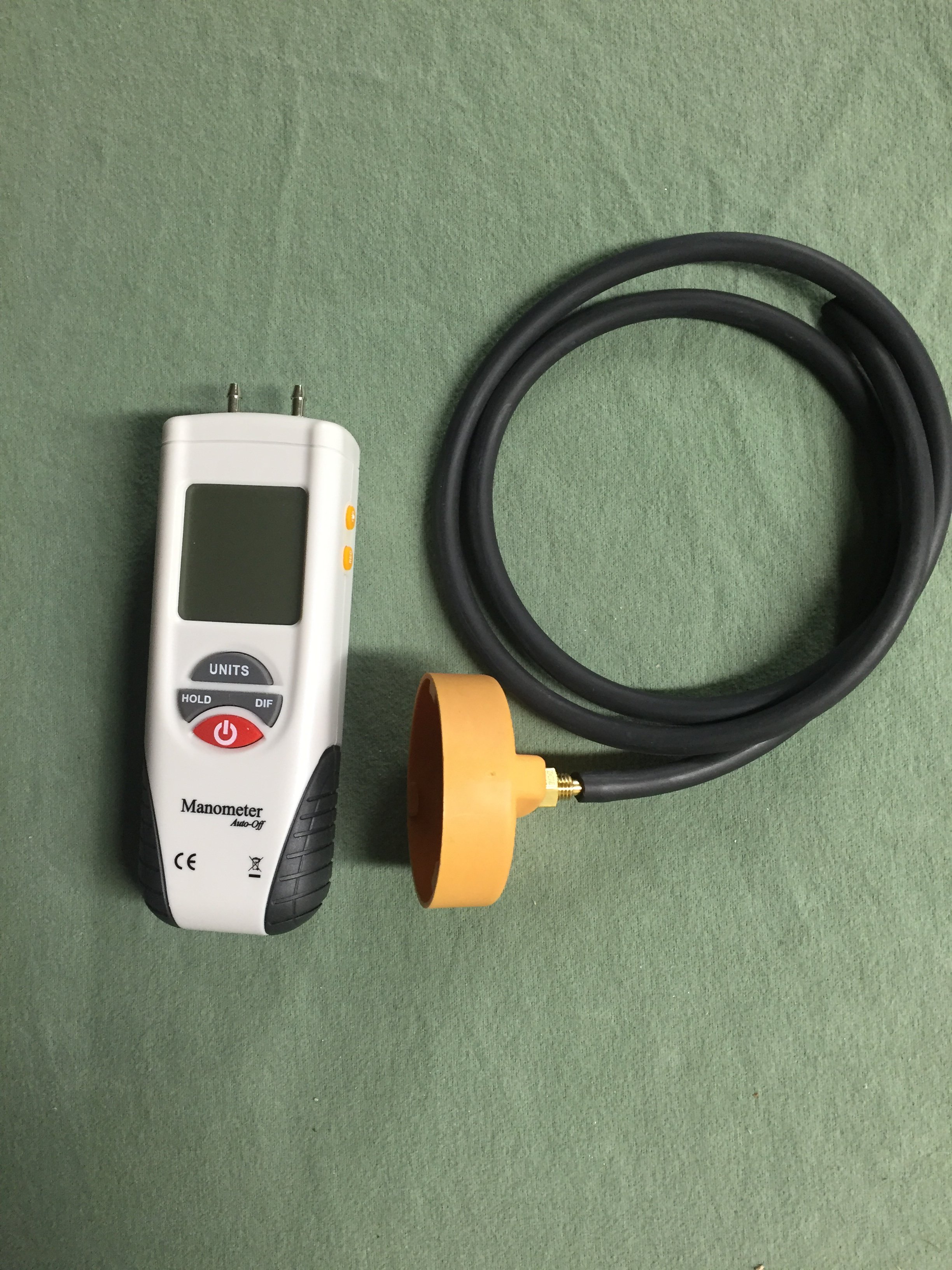
If the oil cap is hard to remove, you have a high vacuum level in the sump, which is bad for a variety of reasons, including lean stalling. The correct way to access the AOS is to fully warm up the engine by driving the car for 10-15 min, then replace the oil cap with the one in the picture above with a hose that connects to the digital manometer. If the vacuum level exceeds 6-7 inches of water vacuum, the AOS is leaking air into the intake system, causing the lean stall conditions. The normal level of vacuum is typically 4-5 inches of water, which is a really weak vacuum level, so it doesn't take much of a leak to cause problems, which is why we always checked every car that passed thru the shop with the manometer.3 points
-
The AOS can either be pin pointed or eliminated by having the car's sump vacuum level checked with a digital manometer (most quality shops have them as the AOS is a perpetual issue; surprise the dealer didn't do this).
 2 points
 -
Welcome to RennTech If you do not have access to a wiring diagram for the vehicle, probably the easiest way to check the ground is to pull the bulb in the light and use a multimeter to check the condition of the ground at the bulb socket.2 points
-
We have used them here in the US for years at MUCH colder temperature's than you get without ANY issues. Put on the adaptor, add external magnets such as the Filter Mag, and enjoy both better filtration and peace of mind.......2 points
-
Welcome to RennTech The factory radio had a ground wire that had to be attached to the car's chassis under the dash as a simple anti theft device. If that ground is not there, the immobilizer will prevent the car from starting.2 points
-
I recently replaced the coolant pipes in my car. I needed to do the job myself because there was simply no way I was going to shell out anywhere from $1500 to $3500 in labor to have it done by the dealership or an independent shop. Plus, having read about the job, I knew they would be tearing through a ton of stuff and I really feared the "oh, it also needs this" scam. I did a LOT of research on the various forums before undertaking this job. Reading and printing out anything I thought was useful information. I would highly encourage anyone reading this to do the same. Fortunately, I was not in the position that the pipes simply failed and dumped all of the coolant. I just had a semi-slow leak… dropping about a gallon of coolant every two to three weeks. So, I had time to order the parts and prepare. Prior to doing this the most complicated thing I had done myself was change the oil, replacing the brake pads and swapping out some plastic bits in the car. I had absolutely no prior mechanic experience whatsoever. However, I do work in IT, and am by nature a very technical person (I'm sure every mechanic reading this just rolled their eyes). My job is troubleshooting very complex problems on very large networks, and I think that experience probably lent itself to a successful outcome here. I'm also patient, and that is critical to getting this job done. I will say that I now have a much greater appreciation for mechanics and their skill set. This was hard. I want to caution anyone reading this that this is a BIG job and it will take a long time. My goal in writing this is so that my fellow Cayenne owners can be spared a lot of the mistakes I made and be better prepared than I was. I will say I am relieved to have this done. I feel a ton better about my car now that I don't need to worry as much about some catastrophic failure hitting me unexpectedly. One rule that I really appreciated was to only place metal on metal when working (until you actually get to removing the pipes). This prevents you from breaking plastic or tearing rubber with something metal. Trust me, pay attention to that rule. I am breaking this down into tasks, because I think it's easier to follow that way. This is how I did it. I am sure there are other ways that may even be easier, but this worked for me and my schedule. I ended up working 4-6 hours at a stretch in the garage with breaks every couple of hours. Step 1: Contribute to this forum I have absolutely no affiliation with this forum whatsoever other than I am a contributing member. The advice on this forum has personally saved me thousands of dollars, and being in IT I know the time and money it takes to run a site like this. So, contribute to the cause. However, there is a second reason to contribute, and that's to get the Porsche TSBs. The TSB for this job contains some diagrams that give you a better idea how all the replacement parts go in to place, and I thought that was handy to have. As an aside, I searched some other issues in the TSBs and found answers to some things the dealership didn't even know… such as there being a $33 replacement latch for my armrest. They wanted to sell me a whole new armrest for $750. Step 2: Obtain the Parts I looked around on the Internet and called some local sources and found a dealership that provided the parts for $550, and that included two gallons of coolant shipped to my door. To me, that was a fair price, and when I received the parts I really thought it was a fair price... there's a lot of quality stuff in there. I'm sure there may be cheaper 3rd party sources. I would just be sure they include all gaskets and such that don't necessarily need to be replaced, but should be replaced if you're tearing everything apart. Once you get the parts, pull them out of the box and examine them. Look at the pics in the forum and look at the TSBs. Get a feel for what you are replacing. Step 3: Verify you have the tools I found the following tools very handy to have, and frankly, necessary. I suggest going to your local auto parts store for most of them and get mechanic grade tools. Socket Wrench 3" Socket Extension 6" Socket Extension Metric Socket Set Torx Socket Set (think of this as a "male" Torx Socket set, you will need #27 & #40) E-Torx Socket Set (think of this a "female" Torx Socket set) Screwdriver that accepts interchangeable bits (there are times this is easier than a socket wrench) Torx Bit Set (Specifically you need a #27 and #40, I just bought a set) Locking Long Nose Pliers (6" is fine, no need for anything bigger) Regular set of pliers Wrench Set (somewhat optional) Real flat head screwdrivers Very long flat head screwdriver (this came in handy a lot) Needle Nose Pliers Small Chisel Set Hammer Tin snips Safety Glasses Mechanics Gloves One of those extension things with a magnet on the end One of those extension things with a mirror on the end WD-40 Some all-purpose grease, like White Lightning Baggies to store the screws in Masking tape/Painters Tape to cover up any exposed openings Old Bath Towels (used to protect the car) Good flashlight Lint free rags Shop Vac Two gallons of distilled water Drain pan (needs to hold 4 gallons) Shop lights A small block of wood, about 2" x 4" x ¾" A radio playing energetic music of your choice Advil and Tylenol Hope and a prayer (optional but doesn't hurt) Step 4: Book the Time I know some people say you can have this job done in less than 8 hours, but being a beginner this took me much longer. If I took out all the time running back and forth to the store for tools and such, and had a guide like the one I am writing, I still think it would have taken 10-12 hours. I ended up removing all of the engine covers on one weekend night, and then doing the actual job the following weekend. I then drove the car for a week with the new pipes and finally put all the engine covers back on over the weekend (I cleaned the covers and the engine thoroughly with a damp rag at the same time to pretty it up a bit). You don't really need to do it that way, but that split the work up a bit. I work in an office in front of a PC all day; I'm not used to working in a hot garage for 8-10 hours at a time... I'm a skinny computer geek : ) When I did the work, I draped some old bath towels over the sides and front of the car to protect it. The last thing I wanted to do was mess up the paint on a zipper or with a dropped tool/screw. Step 5: Remove the Engine Covers There are really two parts to this. You have the decorative covers over the actual engine, and then you have the covers that border the engine. You'll want to remove all of the covers around the border first. There are five of them in total. They all have these little black plastic plugs that you just turn 90 degrees. They should just pop up at that point, but you might have to give them a little lift with a screw driver. While you're removing those covers you might want to pay attention to how they go together and where they slide in to place. You'll also want to remove the windshield washing fluid cap (use the masking tape to cover up the exposed hole) before you remove the cover that surrounds it. Those little things are $4.25 each from the dealership, so try not to lose them. Now you have the three silver looking decorative covers; one on each side of the engine and one towards the front middle with the engine type on it. First, you need to unbolt the two secondary air injection units. Those are the round things with the plastic covers near the back of the engine compartment. You do not need to disconnect them from anything, just unbolt them (three screws each) and then move them off to the side. It might be a good idea to get some labeled baggies to store the screws in. Once those are removed you can get to the side engine covers a little easier. The engine cover in the front middle you just lift off, just work it back and forth a little and it should pop off. Take note that there are four little plugs that fit into holes on the cover itself, you'll need to find them again when replacing it. Now remove the one on the driver's side. It's pretty easy to remove. There are four screws towards the bottom that need to be removed, and then the cover will just come off. The one on the passenger side is a bit different. You have the engine mount right in the middle of things. Assuming you have the tools, you can unscrew the engine mount and get it out of the way. That will let you get to each of the four screws easily on the cover and remove it. I wasn't so lucky here (didn't have the right tools at the time), so I just got the four screws out of the cover and ended up wedging it out. While doing that, the piece of the cover under the engine mount snapped off. I wasn't too concerned about this, because where it snapped is hidden by the engine mount. When I put everything back together I just slid it back and screwed it in. You can't tell at all that it was ever snapped in half. Step 5a: Remove Fuel Pump Fuses You'll want to check your manual (you can also download the manual from this site), but you need to remove a couple of fuses for the fuel pump. Right in front of the driver under the hood there is a small compartment. Remove the cover, and then remove a second cover to expose the fuses. Mine were fuse 14 & 15 for the fuel pump. Store them somewhere safe. Once those are removed, start your car. It will run for a few seconds and die. Congrats, you just removed most of the fuel from the fuel line. I know some people don't disconnect the fuel rail or anything, but to me that's a bad idea. I had a lot of time to try it that way and honestly I'm glad I got it out of the way. Step 6: Disconnect the fuel line The fuel line is near the back center, it's just one tube running to the fuel rail. You'll disconnect it by using a wrench and a pair of pliers. You're unscrewing the part on the left (the thin part) from the part on the right (the wide part) which shouldn't turn as it is part of that tube. Once unscrewed, the fuel rail is only connected to the manifold. A little residual fuel might leak out, so you might want to have a rag handy to wipe it up with. Use masking tape to cover up any exposed holes. It wouldn't be a bad idea to disconnect the batteries now either. I didn't, but that was probably stupid. Step 7: Remove the Y-Pipe that goes to the Throttle Body This plastic Y-Pipe is right up front so it's very easy to get to. There are two flexible pipes on either side you need to remove first; just use a screwdriver to loosen the two clamps on each of them and you should be able to compress them enough to remove them. The Y-Pipe itself is attached to the throttle body via two long, plastic bolts. They have a screw head on them but they are not screws, they're more of a key. You just turn them a bit to line the key at the bottom (use a flashlight and you'll see it move as you turn it with the screwdriver) with the slot. When it's lined up, use a pair of needle nose pillars to lift it straight out. It's plastic and may be brittle, so be a little careful. You will need to remove an electric connection to the throttle body in order to get to one of them. There is a tube connected to the bottom of this y-pipe, so you can't just lift it out. It has some give to it, but not a lot… just enough to get your hand under there once you pull the y-pipe off the throttle body. You have to press the buttons on each side of the tube in order to get it off the y-pipe. Step 8: Remove Emission Tubes & Electrical Connections from Throttle Body There are two emission tubes crossing the throttle body, Porsche refers to them as "vent tubes." I know this because one snapped in half when I removed it, and the dang thing was $130 to replace. To remove them, you just need to press the clips at either side of the end of the tube together and then pull it straight out. I don't think mine had ever been removed, and in retrospect a bit of WD-40 used sparingly here might have been a good idea. I think I used too much force and that's why the small one snapped. I have read that some people have replaced this broken tube with a more generic tube from a hardware store. I just spent the $130 and did it right. There is a third tube connected to the throttle body, you just need to remove that one end of it. You will also have two electrical connections to remove. One you had to remove to get the y-pipe off in the previous step. Just remove the second one and then you're done. Step 9: Remove the Throttle Body The throttle body is connected to the manifold via four bolts. Remove those four bolts and it will come off. You sort of have to wiggle it out because of that thin metal bracket that's holding it there, but it will come out easy enough. Some people take this opportunity to clean it. You'll probably see some gunk on the back side of it on the inside. Step 9: Remove the Electrical Connections to the Fuel Injectors There are eight fuel injectors connected between the fuel rail and intake manifold. Mine were blue plastic, and there is an electrical connection running to each of them. There is a metal clip at the bottom that you just need to press up. I placed a flat head screwdriver between this clip and my index finger, and pushed up and pulled at the same time to disconnect it. Once you remove one you'll get the trick and the rest will come right off. Step 10: Remove the Intake Manifold with Fuel Rail Attached I know a lot of people have different ideas here, some people want to remove the fuel rail independently, and that was the first way I tried it. In retrospect, it's much easier to just leave it attached. There are four screws that hold the fuel rail to the intake manifold. I would recommend leaving these alone, especially since the one at the back on the passenger side is nearly impossible to get to. These screws are $6+ each… I know because I lost one. :P There are 10 bolts that need to be undone to remove the manifold. They don't come all the way out, they'll stay attached to the manifold. Once you loosen them enough they sort of come free and wiggle around. The one at the back on the passenger side was a bear to get to. I ended up placing the Torx Socket bit on top of it using the magnetic extension thing. I then put the 3" extension on top of it, and finally attached my socket wrench to it. I kind of built it all up I guess. I then went really, really slowly and loosened it up. Once loose, make sure to vacuum up any debris on the engine. When you pull the intake manifold off you will have eight gaping holes right down to your cylinders, you don't want anything falling in there. You can now scoot it forward a bit to get to the tubes you will need to disconnect. There are two tubes at the back of the manifold… a firm one and a flexible one. The firm one is just like the one under the y-pipe, and is easy enough to remove IF you can get enough pressure on the connector. The flexible one was just kind of stuck on mine and I left it on. You kind of have to scoot the manifold forward and angle it out, but it will come out with the fuel rail attached. You may have to remove some tubes and such from their guides or brackets. That flexible tube was long enough that I just put the whole thing on the driver's side of my engine and left it there. It didn't seem to be sitting on anything that couldn't support it. I'm sure it can be removed, but at this point in the job I was tired, hot, and just wanted to keep going. Once off, IMMEDIATELY cover up the exposed intake holes with long strips of tape. Cover them completely, and make sure they STAY COVERED. Shine a flashlight in each hole first to make sure nothing fell down there. If so, get it out as delicately as possible. Vacuum up any other debris you see. You can now see the infamous coolant pipes. Step 11: Assessment At this point, you can see the coolant pipes and should be ready for the meat of this repair. The starter is right there too… right under the leaking pipes. Brilliant, isn't it? This may not be true for you, but I had an AMAZING amount of debris in here… honestly looked like a bird had built a nest. I have no idea how it all got in there, but some where at some point tons of debris got in here, and now it was all soaked in coolant. I think my coolant leaking may have been mitigated because the wet debris probably acted as a mud and sealed everything up a bit. I vacuumed it up with a shop vac prepped for a wet cleanup. Now you need to decide if you will see this repair through or not. Once the next step is taken, there is no going back, and honestly the toughest part of this job by far is getting the old pipes out. Step 12: Drain the Remaining Coolant Your first goal is removing as much coolant from the car as you can. On the V8's, there is a drain plug at the bottom of the car, but on the turbo's you won't have one. That drain plug required an allen bit that was larger than I had on hand or could even find at a hardware store. Honestly, in retrospect I wouldn't have even bothered locating it. I'm sure there's a pipe down there you could remove, but I didn't waste time looking for. I took a tip I found on a forum, and drilled a hole right in the middle of the center coolant pipe (of three) and used a siphon with a hand pump to drain out every bit I could. I repeated this process on the larger lower pipe. DO NOT SIPHON BY USING YOUR MOUTH. Coolant is dangerous, nasty stuff. Make sure there are no animals or kids around while you are doing this. WEAR SAFETY GLASSES AT ALL TIMES! Doing it this way you're going to spill a lot of coolant, but it is what it is… they've been leaking all over everything anyway. I used my shop vac to vacuum up anything I could that escaped the siphon. I've also read of people renting professional vacuum pumps to suck it all out, but again, that's more complicated than it needs to be. I did some research, and coolant is not currently controlled by the EPA for disposal, and it can't be recycled. The unofficial advice I got was to dump it in the woods and douse the area with a hose for a bit. Do not dump it down the drain or dump it where animals could readily drink it. Don't dump it in a stream. Presumably it breaks down fast enough on the ground that there isn't a long lasting effect. Step 13: Remove the Three Upper Coolant Pipes The first pipe you need to remove is the long skinny pipe with three connectors. This one is easy enough to remove, and you should have a replacement as part of the kit. One of the connectors broke off in the hole, and I had to very carefully remove the pieces. Relatively speaking this was easy compared to the rest. There is a compression ring that needs to be removed for the connection at the back of the engine, use the locking pliers to do that. Cover up the exposed holes with masking tape. You now have to remove the three upper coolant pipes. There is a bracket at the back of the engine holding the three pipes. There are also two clips attached (you'll be looking at the back side of them) to that bracket that just support a hose at the back (just has electrical connections in it, and it's probably already split so you don't have to be super careful). Pinch the connectors with a pair of needle nose pliers and they'll come off. You now have to remove three bolts from it to remove the upper half of that bracket. I removed two of them but couldn't get to the third without snapping the thing in half. Porsche was kind enough to provide a new one in the kit so I wasn't worried about it. You will now see three rubber hoses attached to the plastic pipes. They are held on to them with compression rings. Use the locking pliers on the rings to loosen them (they need to be squeezed together to loosen) and slip them back over the pipes. I did one at a time, completely removing the ring and setting it off to the side for safety. The locking pliers really excelled here. When using them, attempt to come at the ring from the top instead of the side, the grooves on the pliers will then secure the ring quite nicely. You might have to adjust the pliers a couple of time to get the right amount of the compression for the ring to move freely. With those ends free, I used the shop vac to suck out a lot more coolant. Once done, cover up the exposed holes with masking tape. Once those three ends are free, you'll need to free up the other ends. Here's the deal, they are probably going to break when you try to remove them, and probably going to snap off at the spot where they connect to the coolant reservoir. I twisted and pulled and sure enough, they snapped off. You can remove the lid of the coolant reservoir by removing several screws, a small aluminum pipe on top, and the rubber pipes towards the front of the car. The small aluminum pipe has a single screw that needs to be removed. There is probably a lot of corrosion here so you may need to use a flat head screwdriver to pry it out. Be careful, it's flexible enough to come out and get out of the way but just barely. There is a compression ring on each of the rubber pipes that is easy enough to get to, just loosen and slide it down the pipe. Suck out any coolant and cover the exposed pipes with masking tape. Once you have that lid out, you'll see the remaining plastic bits in the holes. It's difficult to move, but those plastic bits are just in there with pressure, they aren't glued or anything. I used a small chisel and the hammer to break them out. As I got to the o-rings I pulled on those with needle nose pliers and in one instance the whole chunk came out. I also used a lot of WD-40 to work everything out. What you don't want to do is take any risk of chiseling into the metal of the lid, so be careful. This is all about removing the plastic material. Each bit you remove gets you one step closer to freeing up enough pressure to get the remaining bit out. Once it's all clean, leave it off to the side while removing the big pipe. Step 14: Removing The Big Pipe This one is tough. Make sure you're rested, well fed, and cooled down a bit. If you're aggravated already, walk away and relax a bit. You will need to break this pipe into two pieces. I used a boring bit to drill a big hole in the top, and then used tin snips to cut chunks out until I got it in two parts. Again, I used a shop vac to suck out any remaining coolant as I went along. Really, anything will work… you could even use a chisel to break it out. It's coming out one way or the other, no need to be pretty about it. Once it's in two pieces, you can probably rotate the two halves apart. Use WD-40 generously on the ends first though, and give it a bit to work in there. Regardless, when I went to pull out the two ends, they ended up snapping off… leaving their end pieces in the hole. If you read through the three forums, different people use different techniques to try and avoid this with mixed results. This is the worst case scenario though, so lucky for you I fought through it and have plenty of advice. Assuming your pipe broke off as mine did, you will see a metal ring in each end, with black plastic between it and your car. That metal ring was an inner support ring for the original pipe and needs to be removed. This is a violent procedure. IMPORTANT: I cut up some lint free cloths and stuffed one into each end as far as I could so that any material from the following procedure wouldn't go any further. Once done with the procedure below, I vacuumed up anything I could and then removed those cloths. Again, use WD40 a LOT. I sprayed and sprayed as a worked, and I think it helped. READ THIS CAREFULLY: Removing the plastic and metal ring from each end is all about removing material. You are trying to get as much plastic out as possible. If you get the ring out first, great, but it's not 100% necessary. The plastic is what needs to come out, and you need to get it out from all around it. In addition to the plastic, there are two o-rings in there, so they are just adding more friction preventing this from moving. You'll get bits of that out as you work, and that's good. Eventually, you get enough bits out that the rest will just fall out. Use a hammer and chisel to collapse the metal ring on the top and sides as much as possible. I used to the chisel to cut in to it a bit too. Once I got it that far, I switched to the long screwdriver, hammering the end of it into the plastic over, and over, and over again. I pried as much as I could and worked out bits of material. This took a long time, but sometimes you'll get a big chunk out and that will give you renewed hope. Again, this is all about material removal. Keep telling yourself that. Every bit you get out makes this easier. Once you get enough plastic out, you'll see the metal ring move a bit as you work. This is a great sign and you are almost done. Ultimately, you should be able to pry it out with the screwdriver. NOTE: When working you want to work as much towards the metal ring as possible. You want to avoid scraping the inside of the hole where your new pipes will go. I did scrape up mine a bit, it's unavoidable, but regardless my new pipes don't leak. When you go to remove the bits closest to you, you're working somewhat blind and it is hard. This part almost broke me, but I used a mirror to check and recheck my work as I went along. Bright lights help here too. Honestly, I really can't say enough how hard this part was and how long it took in comparison to everything else. It was the part that had me the most worried, but I got through it. Once it's all out, remove the cloths from inside the pipe and vacuum a lot. Now is the time to clean stuff up too, as you're about to put the new pipes in. As a best practice, you should clean up the inside of those holes. I used some steel wool; I know some people used scotch bright or even buffing pads. I didn't go overboard with this; I just want to get any grime out of there. Step 15: Install the New Big Pipe At this point you should be elated. You're through the worst. Installing these pipes are a bit difficult, but not bad. If they are not already on there, put the O-Rings on the small pipe. Use the White Lightning grease or whatever you bought and coat the inside of the hole on the engine and the outside of the pipe. Use it liberally. A bit of WD40 wouldn't hurt either. Press it into the hole at the back of the engine and do your best to get it all the way in. This is where a small block of wood and a hammer come in handy; you can use those to tap it in the rest of the way. Do not put the rubber sleeve on it. For the big pipe, install the o-rings and lube everything up good with the grease, both the hole it goes in and the pipe itself. You will also need to grease up the end the rubber part goes on and the other end of the short pipe that the rubber sleeve will slip over. Place the tightening rings over the rubber sleeve as well. Slide the rubber sleeve as far as it will go over the pipe. Push the pipe into the hole, I found a twisting action worked well. I also used my metal screwdriver against the bottom of the engine bay as a lever to slide it in the rest of the way (it required a lot of pressure). You then need to rotate it to line it up with the short end of the pipe. You'll slide the rubber sleeve over it and then tighten up the two rings. NOTE: Be sure to rotate the rings as far down as possible so that the screw does not interfere with the three pipes you're about to place on top of it. The new big pipe should be in place, and you're now done with the hardest part of this job. Step 16: Install the Three Pipes You'll want to put the lid back on the coolant reservoir (replacing the seals Porsche included with the kit), reattach the pipes and tighten up the screws. DO NOT OVERTIGHTEN THE SCREWS. I snapped one clean off. Make sure they're tight, but don't put all your muscle into it. Once on, you are ready to slide those pipes in. You do not need to put the lower bracket at the back on first; I did it after installing the pipes. Again, make sure everything is lubed up well so that any points of friction are well covered. Slide the pipes in. I used by long screwdriver again as a lever to apply the necessary pressure. On both these pipes and the big pipe it looked like I could have gone another 16th of an inch, but nothing leaks so I guess it was far enough. Put the bracket on at the back before you attach the hoses. You'll use your locking pliers again to attach the compression rings. With the bracket in place it is obvious how far up the hoses go. You'll put the upper bracket on, using the spacers for the screws and screwing it down tight. Don't forget to attach the two brackets that hold that electrical cable in place. Not a big deal if you do forget. Step 17: Install Final Pipe Now install that skinny pipe. This one is easy. Don't forget about the small compression ring that goes at the far end. Everything else just clips in. Step 18: Assess Your Work Look over everything and make sure it all looks right. At this point you should have a sealed coolant system. Check all your connections and make sure everything is solid. At this point you're home free, and you should be feeling pretty darn good. Step 19: Fill Up Coolant I use a 50/50 water to coolant ratio… so I mixed everything up with what I had and filled up the coolant tank. Once it was full, I left it overnight and checked in the morning for any fresh coolant. I was totally beat from a long day of working on it and thought putting everything back together fresh in the morning was a good idea. Step 20: Put Everything Back Together You tore it apart, now put it back together. I cleaned everything as I went, so now my engine looks great and I think that's a good idea. You don't need to go overboard, just use some lightly damp, lint free rags and wipe everything down. Porsche should have also provided new seals that go on the bottom of the intake manifold. I replaced mine dutifully, and I am glad I did. The old ones just looked worn out, no way they weren't leaking. Putting everything together is pretty straightforward once you've taken it apart. Just be careful and make sure you get all electrical connections and hoses in back on securely and in the right places (hard to mess that up). Also make sure you remove every bit of masking tape as you go. Final Thoughts I am very, very glad I did this project for two reasons. One, it saved me a ton of money and two, I now know tons more about the engine. Doing this project means I could replace my fuel injectors, spark plugs, injection coils and a host of other things when and if I have to. I know where the throttle body is, and if it's sticking I know where to go to clean it. If I need to replace the starter, I know where it is and how to get to it. I can now take my car on trips without fear of a massive coolant leak. This was the last "major" Cayenne defect for me that needed to be fixed. The water pump & drive shaft were already replaced. With 116,000 miles, I have quite a bit of faith in my car not having a catastrophic failure (knock on wood). At the end of the day, I'm pretty proud of myself for getting this all accomplished, and I hope I've saved some other poor soul a ton of time by writing all of this down. If it does help you out, please reply to this post and let me know.2 points
-
Many times the servo is not bad but the foam from the flaps has deteriorated and jammed their movement. I would check that first then rest the codes and test before actually replacing any servos.
1 point
-
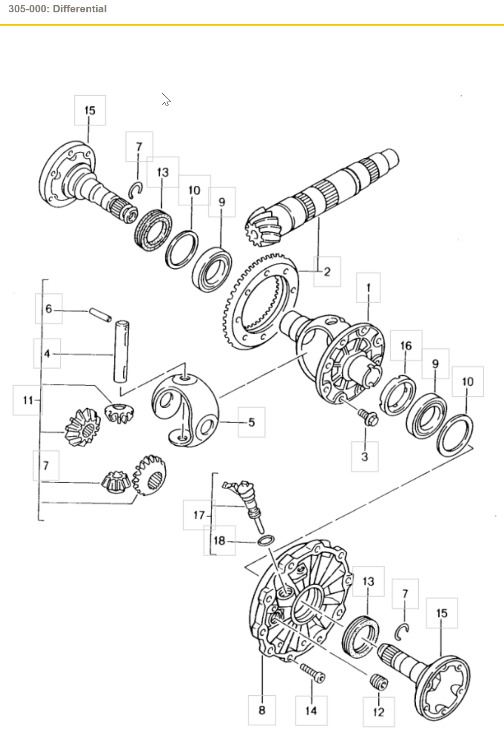
Item 13 is the radial shaft seal. (click the image to enlarge it)
1 point
-
Remember the new ride height will be 10 mm lower than the stock height - plus the springs, struts and swaybars will all be firmer than the stock items. As I said before another option PSS-9 (adjustable) Coilovers - likely easier to find as either OEM or aftermarket.1 point
-
Blue/white marking are stock springs. For factory Sport Suspension you will need new springs, stuts, and swaybars. RoW Sport Suspension Package for 3.2S 6 speed - Carnewal WWW.CARNEWAL.COM1 point
-
I waited until I could confirm my problem is solved. After asking the dealer multiple time about vacuum level measured with a digital manometer and never getting a straight answer, I spent some time talking to the tech before proceeding. According to him, the reason the car would start when cold is it was still going through the 90ish second startup sequence with secondary air injection, coupled with the vacuum leak caused by the AOS. Which, to my not-very-Porsche-tech brain kind of made sense. After getting the AOS replaced, along with a cracked brittle oil fill tube and one or two other related minor bits that were also old, cracked and or worn out, the car seems to run fine, was actually quieter than I ever remember, and the stalling problem is resolved. And no CEL since the repair. There was never any big clouds of smoke usually associated with a failing / failed AOS.1 point
-
Still Fighting the misfire, local shop checked some things and found that my battery cable, the bolt that goes through the fire wall and starter / alternator cable needs to be replaced ( starter also ) before they go farther with diagnostics. $720 for diagnostics and $4000 to replace above parts (parts included) Payed for diagnostics and did all work myself. Still same problem - misfire on cyl-1 and sometimes on 3 ( misfire on 4 was just loose coil from my sloppy install ) work in progress 😞1 point
-
Try 10981 point
-
Try 97861 point
-
Try 89641 point
-
That's trouble. Recheck connections. Use Deoxit on the plug-in connectors. Use fine grit sandpaper (and clean off the grit left by sanding) on the nutted connections. Is it possible you shorted something out as you removed the battery? Were the battery cable ends removed at the battery? Is it the original alternator? It might be possible that it's only the voltage regulator module.1 point
-
What are your voltages? Resting, idling, driving above 2000rpm? There are gizmos to help with this monitoring - Antigravity Batteries has a battery tracker. Others plug into the cigarette lighter. Do you have any codes (can be read with Durametric and other (OBDII) readers)? I've read stories on Rennlist about induced electrical noise in the sound system even when the sound system is not turned on. Might your alternator be damaged or no longer have a high quality ground? Could the noise be mechanical (transmitted noise)? You did change pulleys. Run the car a few minutes without the serpentine belt and see if the noise is reproduced.1 point
-
Try 45051 point
-
Try 07581 point
-
Sorry I have not replied. I did not buy the Cayenne it belongs to a friend of mine and I enjoy working on them when I have time so I spend a few days a week fixing stuff. It been fund and I love finding something that is bad from either age or the last repairman messed something up. so far I have replaced both valve cover seals with the cam actuator seals and spark plug tube seals and new spark plugs. I also replaced the vacuum pump and fixed the power brake vacuum hose that was cracked on both ends, I also replaced the purge valve. I also made a new vacuum line from the oil air separator to front timing chain cover out of copper pipe with rubber ends. I was very pleased to see how nice the motor runs now. I also replace the rear hatch actuator to unlock the rear hatch before you would hit the button but it would not unlock you had to use your finger to manually unlock it from the inside. that's fixed now. Right now I have the head liner and the sunshade off and getting ready to clean the old headliner before I put in the headliner but, before I put back the headliner I'm going to replace both struts for the rear hatch, the glass does not stay up at all and the hatch does stay up but it slams when its closing. I also fixed the drivers seat back cover that kept coming off, I ran a screws 1/4 through bottom of the back cover to hold it to the seat. I have to do the same thing to the passenger side seat too. once I have everything fixed inside the car I need to see what the oil leak it has/had is coming from it could be from old valvecover seals that I replaced or the transmission is leaking. when he first dropped off the car the oil leak was massive and now after the work I have done to the car the oil stain is a drop so that may be fixed, but I need to see and make sure. Oh I'm having a problem finding the struts for the hatch the car has the power liftgate, I find the struts for the glass but I can't find for the power lift gate, does it now use struts for the hatch on the power lift get?1 point
-
Try 67041 point
-
Try 50481 point
-
Because it is a 2005 engine, it would most likely have the oversized third generation IMS bearing in it, which means it cannot be removed without total disassembly of the engine because it will not fit through the opening in the engine cases. One way to know for sure would be to pull the trans, clutch and flywheel off and look at the nut on the IMS bearing center bolt; if it is 22 MM, you have the oversized bearing, which was the only one to use that large a nut.1 point
-
The engine serial number would have been built in late 2005 or early 2006. Porsche rebuilt engines always get the latest parts and a warranty. To be sure you would have to open the engine to get the IMD diameter. If you want insurance then you can install one of the 3rd party IMS oiler solutions. IMS Solution: Oil Fed Plain IMS Bearing - No Ball or Roller Intermediate Shaft Bearings LNENGINEERING.COM IMS bearing failures are expensive. The IMS Solution is the only permanent solution to the IMS problem. Proven protection and the industry’s best warranty.1 point
-
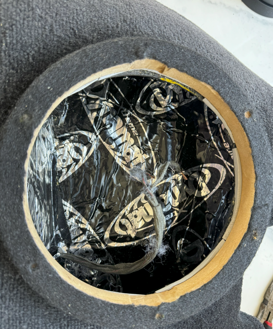
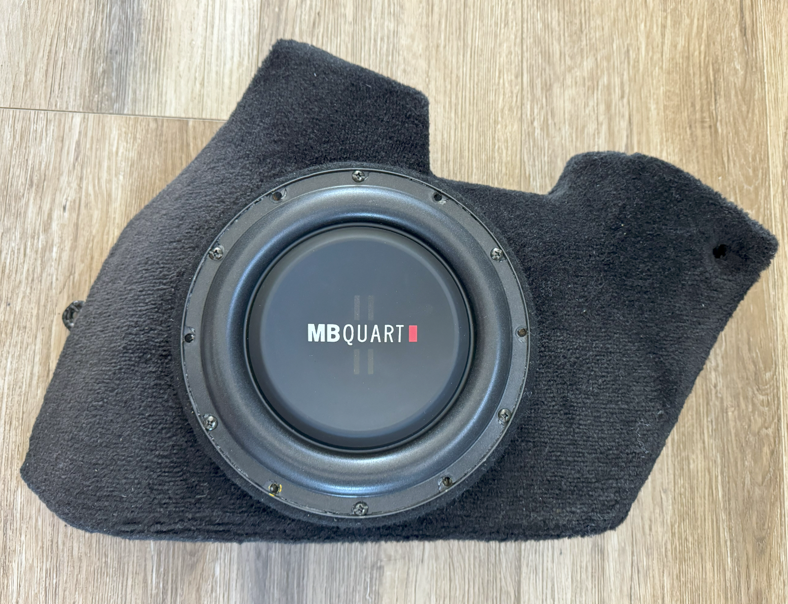
Thanks for the heads up! Maybe they meant litres. I fixed my lack of bass with gutting the stock cabriolet subwoofer enclosure and sealing it for a proper 8" DVC subwoofer install. Super happy that I did and only cost me my rear speakers since running 5 channel amp. Cut a hole in the box and flipped it over and cut to epoxy the old speaker hole closed. Added more foam to the "bass tube" after trimming to seal the whole enclosure.
1 point
-
Time to run a parasitic drain test, which has been written up multiple times, but there are also a ton of online videos : . Basically, after the car has been sitting for about an hour or so, there should be a 45 - 60 milliamp current drain on the battery from necessary things like the clock and the alarm system; any higher than that and you have a parasitic drain on one or more of the electrical circuits.1 point
-
I found my emergency release cable behind the driver's side rear wheel plastic wheel housing, towards the rear bumper. I had to remove the rear wheel to gain access to the plastic screw and the plastic nut that holds the plastic housing to the frame of the car. I didn't have to remove the housing entirely, though. I just removed the two fasteners and pulled the housing enough so I could see into the area behind it with a flash light. Lo and behold, the emergency release cable was sitting there waiting to be fished out!1 point
-
We did this for all Carrera variations so it's time we added for the Boxster's too. Measure the position of the logo with a measuring tape according to the model variant and affix it to the rear lid. Logo Boxster -- 3 A dimension X = 285 mm and Y = 45 mm Logo Boxster S -- 3 A in connection with the letter S dimension X = 245 mm and Y = 45 mm Logo S -- 3 B dimension Z = 20 mm and V = 40 mm
1 point
-
On my 2000 C4 I was lucky enough to have nylon screws. They broke of course, but drilling and tapping was easy with a few tricks and observations: Using a soldiering iron to melt a hole through the center of the nylon screw makes drilling MUCH easier Used a 3/16" drill bit to remove the majority of the nylon then used a 6mm x 1.0 to clean the threads Plunge depth is 3/4" Use a "bottom" tap rather than a "tapered" tap so you clean threads quickly and without significant insertion.
1 point
-
OK. With a "little" poorly documented and explained help from this forum I managed to remove my right rear window regulator from my 2003 Carrera 4 Cabriolet. I am going to provide as many pointers here as I can to make this effort much easier on the next DIY mechanic. Thoroughly read this and other forum posts first. Convertible top needs to be down or in the service position. Remove rear seat cushion, rear interior panel and rear window trim piece as described in this post or others. Rear seat back should be in the up position. For removal of the regulator itself...The total of number bolts and or nuts to remove is 9 (13mm) (possibly 2 more(11mm) if your window is stuck in a down or partially up position). For total of 11. (2) 13mm nuts - Convertible top hydraulic piston; (1) from the rear piston mount point and (1) from the front piston mount point. (3) 13mm bolts - Seat belt pillar; (2) from the face of the pillar and (1) from the top of the pillar where the seat belt loop is mounted to the pillar. (remove the loop and seat belt pillar insert to allow regulator to eventually be removed. (1) 13mm bolt - center of the convertible top support bracket; this is required to allow the bracket to be pried away from the pillar (see 30mm block of wood) to create clearance for the regulator to be removed. With a pry bar of some kind you should set the block in place at this step. (3) 13mm nuts/bolts - window regulator mounting points (recommend removing these last); (1) nut at the bottom accessed by removing a rubber plug; (2) each at the top; (1) one rear and one front. For the rear remove a styro foam plug to access with socket. For the front; if the window is in the fully up position access through the aligned opening in the convertible top support bracket. (IMPORTANT) If the window is stuck down or partially up this front bolt/nut is not accessible. The window blocks access to it through aligned opening in the convertible top support bracket. Follow these steps... you will need to use a goose neck closed end 13mm (6 point) wrench; loosen and remove this bolt/nut. Place or stuff a rag just under this nut/bolt to prevent it from falling to the bottom of the body cavity should you lose a handle on it. remove rag, regulator should now be free to move upward but not out all of the way out BECAUSE the window (still attached to the regulator) CANNOT clear the seat belt pillar. move the window and regulator upward sufficiently enough so the window mounting nuts (the (2) additional 11mm noted above in item 1) are accessible with the 11mm socket; loosen to free the window from its regulator seat. (be careful not to scratch or break the window by applying to much force) Carefully remove the window from the regulator and you will now have sufficient clearance to remove the regulator from the car. Remove the regulator by pulling it up first (free the bottom mounting bolt from its bracket) and then towards the rear (got to get the motor to clear the body) then straight up. Take it slow. It will come out. Good luck. Its not really that difficult once you see what needs to be free.... and the window itself is out of the way.1 point
-
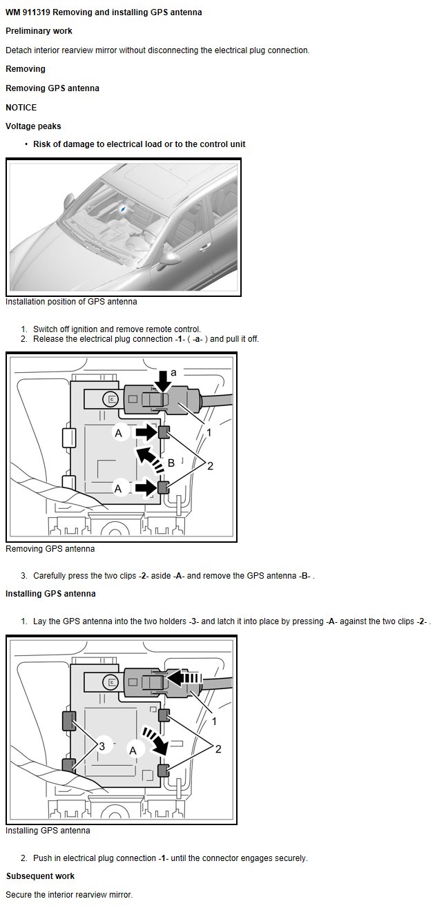
Osunick, Your GPS antenna is located behind the rearview mirror. Hope this helps.
1 point
-
Try 65131 point
-
I will be posting a starter repair/cleaning tutorial for the Porsche Cayenne. I bought a 2006 S a few months back and it had the startup whine that I believe is common to this vehicle. I have replaced the old starter with a Chinese $130 job, but I don't trust that the starter will last. I was amazed that no one had posted a DIY for this since the new Bosch starter is so **** expensive. As of right now I have most of the starter disassembled (which was not difficult except for one part that I can't figure out). As I clean and put back together I will post pics and advice. I found a few sites where you can get starter parts, mostly in Great Britain. I used a parts company called saverepair.com. Unfortunately, Bosch doesn't supply a lot of parts specific to this starter. The starter number is 0 001 125 025. Other good reference sites are aspwholesale.com, https://en.as-pl.com and this parts breakdown helped TREMENDOUSLY http://www.woodauto.com/Unit.aspx?Man=BOSCH&Ref=0001125025 (which wood auto was my second choice for parts but they cost a bit more.) What I could order from saverepair.com were these parts. bsx208-209 Bosch Starter Motor brushes 5.8 mm x 18mm x 14.6mm. 1 €3.60 €3.60 wsbu9016 Starter Bushing 10,08mm x 14,04mm x 9,90mm Rear bushing for Bosch,Front Bushing for Valeo D7E, and Centre for Ford Motorcraft. 1 €0.55 €0.55 wsbu9022 Starter Bushing 28,47mm x 32,30mm x 10,00mm. Front bushing used in Self-Supported Bosch starters. 1 €1.72 €1.72 wss0020 Starter Solenoid for Saab 9-3 Turbo 9-5 Turbo 900 9000 Opel Astra F Corsa A B Kadett E Vectra A B Lancia Fiat and more. 1 €18.00 €18.00 Pretty cheap parts as you can see. When I received the parts I was a bit concerned that the solenoid wouldn't work (I basically picked it by cross referencing starters that were close to the number range and had the same type of connectors). This solenoid is a bit larger than the old one, but the screw holes match up perfectly. I have never replaced bushings or brushes before, so this will also be an adventure I'm sure. On a side note, I REALLY wanted to replace the main bearings on the starter, but there are a few things I can't figure out. There is a part called the bendix that has the gear at the end that also holds the bearings. It is also attached to the stationary gear and a spiral gear shaft. I can't figure out how it all separates. If I did, I could just replace the entire bendix with the bearings on it. I'll see if I can attach a pick of what I'm talking about. If I can't get them separated I think it will be fine as the bearings still turn. I believe the major points of wear on the starter is the bushings. There is wiggle and play on the shafts on the bushings, which is probably why the starter was whining. Stay tuned! One more thought on removing the starter itself. There are write-ups for that so I won't delve, I will say, it is a relatively easy job of removing parts to get to it, but it does take a lot of time. I was able to remove the starter also without disconnecting coolant lines. I also added a pic of me after ripping the engine apart, with a much rewarded pipe blend called "quiet nights" (completely irrelevant to the post, ha!).1 point
-
Porsche book time 270 time units per side. 100 time units equal 1 hour. Time to get another quote or DIY.1 point
-
2001 C4 Cab. 58k miles. I have this exact problem, ticking that happens at idle, but slightest depression of clutch pedal makes it stop. Got new clutch 4 months 4 k miles ago. The noise started a few weeks ago,. Any idea how in the world the clutch master could be making that noise? Reluctant to replace without seeing how it could be the problem. Thanks.1 point
-
Latest: Faultless starting, hot or cold, during past 2-3 months.1 point
-
Dave, As Silver said, it should not be too difficult to track down the problem(s). All you need is a $15 multimeter. Run your engine till warm and the low voltage shows up, then let it idle and turn on the a/c and the low beam. The current draw from the alternator should now be ~50A. You can then do the following tests. I drew a diagram with the corresponding parts. Test #1: check voltage drop between point "C" (alternator casing) and "B-" (call that V(C, B-)). Note "B+' and "B-" are the actual battery terminals, not the cable connectors on the terminals. This test shows total voltage lost between the alternator and the battery on the ground side. Expect 0.2v or less. If your ground strap is bad, it will show up in this test. Test #2: check V(A, B+) where "A" = alternator output at the back of the alternator that you can't see (use an inspection mirror) and expect ~0.5v or less. "A" is hard to get to. I fabricated a J-shape hook using a stiff insulated wire and just literally probe it blindly from behind. Wear protective goggles here since you will be close to the drive belt, a hot engine, and the always LIVE "A". This test shows total voltage lost between the alternator and the battery on the power side. Test #3: check V(A, J) and expect ~0.2v. This tests #21, which is the infamous cable that can corrode and Porsche has also revised it. Test #4: check V(J, B+) and expect ~0.3v or less. Test #5: check V(A, C), your alternator output and expect 13.5v or higher. Your problem is gonna show up in one of the tests above.1 point
-
Thanks everyone for your ideas. I first tested the fuses - ok. Then I tested the relays - both low clicked when I had a fingertip on them and turned on the A/C. Then jacked up the car to test the fans - both turn freely. I then started the car with the A/C on and the right fan turned on and the resistor got hot. Left side did not turn on and resistor was cold - looks like I found the problem. I will order the resistor harness and replace just the resistor as it seems easier than trying to install the whole harness. Should I also test the high relays with the fingertip test - should they click as well if A/C is turned on - or they will only turn on when water temp/A/C pressure is high? Thanks again!1 point
-
I could not disagree more. You want the TB to be dry as only air passes over it.1 point
-
I have a 2005 Carrera S with 68,000 miles. I recently started having problems with a large white cloud appearing only at start-up and some poor throttle response at low rpms. I had also noticed for the last few months that the oil consumption seemed a faster than usual for my car. After a little reading I found that it might be due to the AOS. My Durametric program was giving some RKAT and misfire codes, but the check engine light (CEL) was not on - of course, after I checked the codes, the CEL came on. With the engine running, I tried to remove the oil filler cap but couldn't - I would have had to pry it off the tube. So it really did seem to the AOS. Apparently when the AOS goes bad, it causes a high vacuum in the crankcase (hence can't pull off the oil filler cap) and this pulls oil into the recirculation system that drains into the intakes (hence the white cloud at start-up and high oil consumption). I looked around and found some information on Rennlist discussing AOS replacement on a 996 (http://forums.rennli...labor-time.html). People discuss dropping the transmission or lowering the engine to help with this. I'm my case only removing the engine would have helped. The hose clamps are pointed towards the back of the car so I would not have been able to do this from the transmission side. You should know that the 997 S uses a different AOS than the non-S 997 or the 996. Based on all this information I ordered from Zim's (www.allzim.com) AOS for ~$150 3 intake gaskets (~$8) (didn't use these in the end) one throttle body gasket (~$7) as well as a new serpentine belt, and all three idler pulleys (pullies?) because I thought I would do this at the same time. Tools are shown and with some listed at the bottom. First, the pre-picture . Obviously I have a fabspeed cold air kit. The red color sticks out like a monkey-butt, but I like the sound. The AOS on the 997s is under the passenger side intake manifold about halfway to the front of the engine. So some things have to come off... the air box needs to come out, there is a good air filter replacement tutorial here on Renntech. This picture shows the air box partially out and rotated over so that you can see the connections. I also zoom in here just to show the vacuum connection on the solenoid, one of the electrical connections on the solenoid (already disconnected), and the mass air flow (MAF) sensor connector. Just ignore the broken wire clip. Some gremlin must have done that... Now the throttle body has to come off - there are four E-10 bolts, and the bottle left one has a bracket that hold a little rubber bumper attached to it. Only the four E-10 bolts need to come out. There is also an electrical connector at the top (runs from left to right) and if you squeeze it just right on a tuesday with a full moon, it will pop off. Here are two pictures of the throttle body off the car, note that there is oil on the inside and both the inside and outside need cleaning. Now to get the intake pipe out from between the left and right manifolds. You can see that there is the plastic Y splitter that the throttle body attaches two, and then two short rubber hoses that attch the plastic splitter to the intake manifolds. There is a recirculation hose connected to the top left of the splitter. The other end of this hose is connected to the AOS. Porsche was VERY nice when they made these hoses, if you squeeze the two textured parts together the hoses pull off easily - no wire hose clamps. Yeah Porsche! Also notice that this splitter piece has the groove where a new throttle body gasket should go. Each rubber hose has two large hose clamps on it. In order to get the splitter out, I recommend loosening only the two outer most clamps, that is the clamps on closes to each intake manifold, because then you can rotate the splitter up or down to help break the seal of the rubber hoses on the intakes. Then I removed the inner two clamps and broke the seal of the rubber hoses to the splitter. To get everything off, I pushed the rubber hoses as far onto the intake manifolds as I could (essentially pushing the two rubber hoses father apart) , and then the splitter came out from between the hoses. In retrospect - and after putting all this back together, I would have pushed the rubber hoses closer together onto the splitter and then taken out the splitter with the hoses attached as it went back on this way pretty easy. Here is the splitter And here is where the splitter was... In this last picture you can see the short rubber hose segments, the disconnected recirculation hose, and the back crossover tube that also connects the two intake manifolds. If you follow the disconnected recirculation hose down, you can see the top of the AOS. I could see that a fair amount of oil had collected in the intake system. I also removed the power steering reservoir - there is a 10mm bolt on the right side holding it to the right intake manifold and a plastic tub that connects down to the pump. That tube has a nice twist connector on it, twist it to the left (counterclockwise) about a quarter of a turn and the whole thing will just pull out. This picture shows where it was, and the black plastic tube that has a green o-ring is where that reservoir was connected. Now I removed the 4 E-10 bolts that held down the right intake manifold to the cylinder head. This is where things may have been easier on the non-S or the 996? My intake manifolds are one piece with the injectors attached to the bottom. There are 4 bolts, one on each end and one between each pair of cylinders. If we number them from rear of car to front, number two was the real pain to get out. There is a sensor embedded in the manifold directly above this bolt which made it difficult, but eventually the right combination of extensions and u-joint made it possible (it was harder to replace than to remove). I couldn't really get a good picture here. I couldn't easily figure out how to get the fuel supply line and injectors disconnected, so I couldn't pull out the intake. Removing the intake bolts did left me move it around some which was helpful, but I'm note sure it was actually necessary to get the AOS out. Also, since I couldn't get it off, I couldn't change the gaskets - so I'll keep my fingers crossed that the old gaskets are still in place. This picture shows that I've removed the old AOS - you can see the recirculation hoses that attach to it (there are three - two on the left and one on the back), and then two small coolant hoses (both on the left). What it doesn't show is that there are two small T20 screws that hold the AOS to a bracket on the cylinder head. See the diagram below for better idea. I sure hope your hands are any larger than mine... I used a T-20 bit and a small ratcheting monkey wrench to get to these. If I hadn't loosened the right intake manifold, then I'm not sure that I could have gotten my hand in there to do this. There are the two coolant hoses that have to come off, one of them come from the water pump and there is a small segemnt of it that is rubber with a spring clamp right at the water pump fitting. This picture shows where I'm talking about. In retrospect I don't think I had to take this off, but it was easy. Please ignore the broken oil-pipe filler. Who did that? Turns out that this filler just sticks out into space and it is really easy to put too much pressure on it with your arm when trying to work on the intake. It snaps with a nice crisp pop that reminds you of a broken bone. Turns out it is a $40 dollar part that has to be ordered and it looks like the alternator has to come off to replace it. I think I'll keep my serpentine belt and pulleys for a future weekend when I get to change the filler pipe. Also, here I want to show the water hose connection, again an excellent job by Porsche. The blue piece on the end of the hose is a tab, than when pushed releases the connection and the hose comes right off. I only lost about 1/ 4 cup of coolant when disconnecting both water hoses. Lastly, here is a picture of the space where the AOS was sitting. You can see the opening in to the crankcase where the bottom tube of the AOS fits. A little wiggling and the new one slides right in. I cleaned everything using a carb cleaner and P21 citrus cleaner. Now that everything is apart, it's time to put it together. 1. new AOS in, connecting coolant hoses first and then getting the t20 screws into the AOS from the right side of the engine. 2. connect recirculation hoses to the aos, and the coolant hose back to the water pump fitting. 3. reconnect the rear crossover tube by pushing the rubber hoses as far as possible onto the intakes - again this helped that my intake was loose (take special care to get the vacuum connection reattached - I had to disconnect this vacuum hose over on the left intake manifold so that I could get enough slack to work with it, once it was back on I reconnected the vacuum hose on the left intake manifold. 4. put the bolts back into the right intake manifold, I did each hand tight with a socket extension and then torqued each to 7.5 ft-lbs (this seems right) - I also had to reconnect the sensor connector over that #2 bolt. 5. then I adjusted the rear crossover tube and then tightened the hose clamps (not too tight). 6. Then I put the front intake splitter and rubber hoses back on, to do this I pushed the hoses all the way onto the splitter and fit it between the intake openings and then separated them onto the intakes. Worked pretty well. 7. lined everything up and tightened the hose clamps (not too tight). 8. connected the recirculation hose to the splitter 9. Replaced the power steering reservoir, twisted the pipe connection to lock and replace the bolt into the right intake manifold 10. put new gasket on the splitter to throttle body face. 11. put throttle body back on the splitter - (torqued these to 7.5 ft-lbs also) 12. replace the air box with the two electrical connections and the vacuum connection. (13. duct tape the crap out of the oil filler tube to hold it and seal the vacuum until I can replace it) I'll say, there is some satisfaction in knowing that part of my $100k car is held together with duct tape. I started the car and filled my garage with white smoke - there was still some oil in the system from the last time it was stopped, but the car idles lower, better low end response, and I can get the oil filler cap off without giving myself an aneurysm. The posts I've seen say that it will continue to smoke on start up until the oil is cleared out. Might have done differently: 1. Not sure if I had to take the intake manifold bolts out - I had hoped to remove it, but in the end I couldn't. 2. Probably would remove the belt, and alternator in order to take off the oil filler pipe and get it out of the way - that would have kept me from braking mine.. 3. and if I did #2 above, I would have changed the pulleys and belt at the same time. Time: about 7 hours split over two days, next time might take 5 hours. Tools: here is everything that I used. Note the diet coke, this was necessary in copious amounts. Lots of 1/4 and 3/8 inch extensions and adapters to make different lengths. 7mm, 10mm, and 13mm sockets. An E-10 star socket and a T-20 torx bit (or a star bit) I have both of these from a kit sold by harbor freight. Also came in handy when I changed the spark plugs and coils a year ago. The magnet and mirror are indispensable. I hope you have as much fun as I did. Someone described it like having your hand up a cow's backside, and there are times that made me chuckle. It is always nice to learn a little more about my car. I am in Dallas, and if anyone needs help or has questions, just let me know.1 point
-
You have no Range 2 over revs - you can not ask for better. Range 1 over revs were caught by the rev limiter and don't mean much since the rev limiter protected the engine. Range 2 are the bad over revs.1 point
-
My Porsche is a 1999 996 C2 Cabriolet. The convertible top compartment lid (the “lid”) is attached to the body via two hinges which each have two arms. The front arm on the left hinge was broken, so I replaced the entire hinge, as replacement arms are not available. Here is the step by step process of how I did it :(I had a bunch of great photos with this article, but for some reason they did not copy and paste with the article) (I'm what you might call "format impaired".) : Tools needed: Flat Head Screw Driver 10mm Box Wrench T-30 Torx Bit 13mm Socket Short Socket Extension Electrical Tape Parts Needed: Replacement Hinge Part #996-561-907-02 (Left side) Replacement Seal Part#996-561-904-00 (“Cabrio Plate” in Porsche terminology) 1. Open the top partially so that the top is open about half way and the lid is in the fully open position. 2. Disconnect the cables that keep the rear-most part of the top secure to the car. There is one cable per side. Push the cable inward (toward the center line of the car) to release it from the ball connection. Release both cables. 3. Let the top move forward toward the closed position and push the window section up and out of the way. 4. Use the flat-head screw driver to remove the 4 plugs that keep the rear carpet in place. Remove the carpet, starting at the top and working it around the trim. 5. Once the carpet is out, follow the lid stop light wire down and disconnect it. It simply unplugs. 6. Release the wire from fastening elements (Porsche terminology) on the rear arm of the left hinge. 7. Mark the location of both left and right hinges in relation to the lid, then use the 10mm wrench to remove the 2 nuts securing each hinge to the lid. Prior to removing any parts, cover the drain hole below the hinge with a paper towel to prevent any small bits from falling into it. Once broken loose, they can be turned by finger. (This is probably better done with the assistance of a helper to support the lid, but can be accomplished by one person working alone by removing the rear nuts first and supporting the lid in place with one hand while removing the front nut on each side with the other hand.) Remove the lid from the car by lifting it up off the hinge. 8. (For the left hinge, only.) Remove the plastic fasteners for the lid stop light wire from the hinge for reuse on the replacement hinge. These both just clip on and can be easily remove with needle nosed pliers. 9. Remove the additional flap for reuse with the replacement hinge. The flap is removed by pushing the locking lever forward, then pulling the flap backwards and pulling downwards out from the underside of the hinge top. 10. Undo the motor drive from the hinge rear arm by removing the 2 Torx screws with the T-30 Torx bit. 11. Disconnect the motor drive push rod from the front locking hook at the front of the hinge by releasing the small clip retaining it. It should come off by releasing the locking tab slightly and pushing down at the same time. 12. Remove the motor drive body from the body of the hinge by removing the 2 Torx screws with the T-30 Torx bit. It’s not necessary to remove the pin with the flat head slot on it in order to remove the motor drive from the hinge. It may take a little rocking, but the part should come right off without much effort. 13. To give more play in the hydraulic line to the motor drive to be able to get it well out of the way, with the flat head screwdriver release the tie securing the line to the bottom of the compartment. This just pops off and presses back onto a threaded retainer. 14. Move the motor drive out of the way and with the 13mm socket remove the 2 nuts and 1 bolt attaching the body of the hinge to the body of the car. The 2 nuts are clearly visible, but the bolt is concealed behind a plug in the trim piece covering the front of the hinge. To access the bolt, remove the plug with the flathead screwdriver. (Be careful not to drop the socket or the bolt behind the trim piece as fishing them back out may be a challenge.) Once the nuts and bolt are removed, the hinge can be gently removed from behind the trim piece by pulling up on the back of the hinge and rotating the entire hinge about 90 degrees counter clockwise and pulling up and back while gently prying up on the trim pice with the other hand. (This is probably the hardest part of the entire procedure.) 15. Adhere the seal to the back of the new hinge replicating the position of the old seal on the old hinge. Clean up around the openings in the body panel to remove debris left behind from the old seal. Remove the backing film from the seal before installing the hinge. Make sure the contact surfaces of the hinge and body are not adhered over by the seal. Installing the new hinge is the reverse of the removal procedure: Work the front of the hinge back behind the trim piece; Attach the hinge to the car body with the 2 13mm nuts and the 13mm bolt and torque to 7.5 ftlb.(I used the electrical tape to temporarily secure the bolt to the socket and the socket to the extension to ensure I didn’t drop either down behind the trim piece.); Attach the motor drive to the hinge body with the 2 long T-30 Torx screws and torque to 7.5 ftlb.; Attach the motor drive to the rear hinge arm with the 2 short T-30 Torx screws and torque to 7.5 ftlb.; Reconnect the motor drive pushrod to the lock hook at the front of the hinge with the small clip; Re-secure the hydraulic line tie in the bottom of the compartment; Attach the brake light wire fasteners to the rear arm of the new hinge; Reattach the additional flap by inserting it onto the pins on the underside of the hinge and pulling it forward then pulling the locking lever backward until it locks; Install the lid, leaving the 10 mm nuts slightly loose and press the stop light wire into the plastic fasteners and plug it back into the connection; Reinstall the carpet; Reattach the rear roof cables; Next align the lid, so it will close properly aligned with the body. Using the marks made at the beginning of the process should make this a bit easier.1 point
-
I have a '00 C2, 6-speed, Canada version. I keep an eye on the operating temperature, using the OBD hack rather than the gage. In traffic, the car has always run pretty warm, regularly over 100 C in the spring-summer-fall. Last night, it was up over 105 C, and I thought I'd hop out and check to see if the cooling fans had switched to high speed as they are supposed to at this temperature. On the passenger side of the car, the fan was loud and you could feel air being moved. On the driver side, the fan was on but quieter, and less air was moving. Is this normal? If not, can you suggest an explanation? I can imagine losing a fan altogether, but I can't figure out why it would just refuse to switch speeds. TIA, Bruce.1 point
-
They "pop" off, you can use two flat screwdrivers, a door trim clip disposer fork, or similar tool.1 point
-
Who knew! I was avoiding using search criteria this specific! Thank you, Loren. Looks like the search begins at the fuse panel... Bruce.1 point
-
Installing an MY02 Carrera C2 (Manual) Instrument Cluster in an MY03 Boxster (Manual) I have a few of general observations. First, I selected a Carrera C2 (manual transmission) instrument cluster because, having read through several threads on this forum, there didn’t appear to be any systems compatibility problems with the installation. For example, fuel gage problems with a C4 cluster (due to fuel tank design) or oil quantity/car leveling errors with a Turbo cluster (due to engine sump differences) were some of the problems to be avoided. Once the additional wire for the oil pressure gage is installed, the change over from Boxster cluster to Carrera cluster is truly “plug and play”. Second, it is essential to get a donor instrument cluster that is compatible with your car, in terms of original vs. “improved” cluster design. MY02 and subsequent 996 instrument clusters are improved. MY01 and subsequent 986 instrument clusters are improved. If you just have the hardware in hand, look at the color of the three plug receptacles on the back of the cluster. The original cluster has blue, white and black receptacles. The improved cluster has green, blue and gray receptacles. Third, there doesn’t seem to be a problem dealing with the MOST bus, or absence of the MOST bus. If the installation is done in a MOST bus equipped Boxster, the only anomaly will be the “Porsche Protected” display on the CDR23 radio. This is corrected using a re-coding routine by a PIWIS. If the Boxster being modified doesn’t have the MOST bus (pre-MY03), then entering the radio security code is the only step required after hooking up the battery at the end of the installation. Fourth, because my car is still under CPO warranty, I had my Porsche dealer install the Carrera oil pressure sensor. I didn’t want any arguments if, down the road, there were any problems with the lubrication system that could possibly be attributed to me working on the engine. Fifth, I sent my Carrera instrument cluster to an instrument shop to have the mileage reset to approximate the mileage I anticipated to be on the Boxster when I affected the change. The mileage is stored in the instrument cluster and can’t be reset using a PST2 or PIWIS. I got a receipt from the instrument shop indicating the mileage they reset the odometer to. When the dealer re-coded the radio, I had them verify the mileage on the Boxster odometer and the mileage on the Carrera odometer. The dealer put both mileages on the work order and made an entry on page 1 of the maintenance booklet. Sixth, I had about 7/8 of a tank of gas in the car. Some of the threads I had read suggested that there would be a problem with the fuel quantity indication if the instrument cluster was changed when there was less than 19 liters/5 U.S. gallons of fuel in the tank. After the change, the Carrera instrument cluster fuel gage indicated the same quantity as before, 7/8 of a tank. Due to the winter weather, I haven’t driven the car enough to require a re-fuelling. But, the gage does seem to work properly. Last, my MY03 (e-gas) base Boxster was delivered with cruise control. I had done the OBC/4 stalk “hack” earlier. All functions of the cruise control and OBC work. The OBC display is in the “improved” instrument cluster, dot matrix format. REQUIRED PARTS New/used Carrera instrument cluster appropriate for Boxster, for example: P/N 996.641.223.00.70C Pressure Sensor, Engine Oil: P/N 996.606.203.01 New/used Cover, Instruments, for example: P/N 996.552.059.02 EFM (black) – if you want to use a Carrera part, otherwise modify the existing Boxster instrument cluster surround. Wire Pin: VW P/N 000.979.010 Heat Shrink Tubing: Radio Shack P/N 278-1611 Quick Disconnects: Radio Shack P/N 64-3132 Hook Up Wire, Stranded 20 Gage: Radio Shack P/N 278-1225 Tie Wraps: Radio Shack P/N 278-1631A Most of the Radio Shack sourced parts are well in excess to your needs. But for about $7.00 total expenditure……… REQUIRED TOOLS Ohmmeter 10mm socket with ratchet and short extension Soldering iron with rosin core solder Wire cutter Wire stripper Wire crimper Needle nosed pliers Small common screwdriver 24mm open end wrench T-30 Torx driver T-20 Torx driver 5mm hex key Ice pick or awl Scotch tape Wood matches or electric heat shrink heat gun Dremel tool with ½” sanding drum and 120 grit sanding bands (used if you modify the existing Boxster instrument cluster surround) INSTALLATION 1. Cut a length of about 12 feet of 20 gage, stranded hook up wire. Strip about ½ inch of insulation from one end. Crimp and/or solder a female, quick disconnect to the stripped end of the wire. This end of the wire will be attached later to the new Carrera oil pressure sensor. The other end of the new wire will be cut to proper length and stripped later. 2. Cut the wire pin (VW 000.979.010) in half. Strip about ¾ inch of insulation from the cut end. The stripped end of the wire pin will be attached to the new wire later. 3. Open the engine compartment using the procedures set forth in the owner’s manual (MY03, page 179). 4. From inside the car, remove the upholstery panel on back wall of passenger compartment. Slide both seats as far forward as they will go. Tip both seat backs forward as well. There are four large diameter plastic fasteners at the top of the upholstery panel, holding it in place. Use a small common screwdriver to loosen them; unscrew the fasteners. The upholstery is removed by pulling up on the panel. 5. Remove the forward engine compartment lid. There are seven 10mm bolts and two 10mm nuts. The lid may be difficult to remove if it hasn’t been off previously. 6. Remove the center console. a. Remove leather boot around the shift knob. The frame that holds the boot just unclips; pull the frame directly up. b. Remove the shift knob by pulling directly up. (Some knobs may have a 5mm setscrew). c. Remove the screw found at the forward end of the center console. Torx drive T-20. d. Unsnap left and right upper side covers from center console. e. Unsnap lower center console cover (batwing). f. Remove the CD holder (tape holder) and cubbyhole. They are removed by pulling straight back. g. Open center arm rest. Remove the rubber mat, the screw securing the plastic floor in the oddments tray and the plastic floor. Torx drive T-20 h. Remove screw found on the right forward side of the oddment tray. Torx drive T-20. i. Remove coin holder found on the left forward of the oddment tray. Use small common screwdriver to lift the coin holder directly up. j. Remove screw found under coin holder. Torx drive T-20. k. Remove ashtray (or rubber mat in non-smoker’s tray). Remove two plastic trim screws. Torx drive T-30. The plastic trim screws are threaded into two plastic bushings. If you’re not careful, you’ll loose one of the bushings. l. Pull up and remove the control panel by unclipping the ashtray light (if installed), unplugging the window operating switches and, if installed, the seat heat control switches. Use the small common screwdriver to gently pry the plugs off the switches. The plugs are tight. White switches – driver’s side. Black switches – passenger’s side. m. Remove screw found under the control panel. Torx T-20. n. Remove parking brake cover next to driver’s side seat belt fastener. Pull directly toward the driver’s seat. o. Tip passenger’s seat back all the way back, check all the wires and clips are clear, the parking brake is pulled back as much as it can be and remove center console. Lift the rear of the console while pulling back. If you have the alarm system, be sure the wire to the oddment tray latch is unplugged. p. Unclip window wire bundle from shifter base cover. q. Remove the shifter base cover. r. Using 10mm socket with ratchet and extension, loosen the four nuts that hold shifter assembly. Loosen just enough to be able to lift the shifter assembly up about ¼ - 3/8 inch. s. This information and photographs can be found at bmracing.com by downloading the B & M short shifter installation manual. And, it can be watched on 9X6 Werks, Vol. III. 7. Install Carrera oil pressure sensor. a. Put a cloth, or a blanket, over the right rear fender to protect the paint from scratches. b. The oil pressure sensor is located on the right side of the engine on the intake cam housing. c. Pull off the existing green/white wire off the Boxster oil pressure sensor. Leave the black rubber socket on the wire. d. Using a shop rag and/or small brush, clean the area around the oil pressure sensor of any dirt or debris. e. Use a 24mm open-end wrench to remove the Boxster oil pressure sensor. f. Install the Carrera oil pressure sensor. Tighten oil pressure sensor to 15+-3.5 ft-lbs g. Push the connector of the green/white wire onto oil pressure sensor terminal “WK” (the larger of the two terminals). Push the black socket down over the terminal. This terminal and electrical circuit provide a signal to the oil pressure “idiot light” on the Carrera instrument cluster. h. Push the connector of the new wire onto oil pressure sensor terminal “G” (the smaller of the two terminals). There is no socket available to cover terminal G. This terminal and electrical circuit provide a signal to the oil pressure gage on the Carrera instrument cluster 8. Route the new wire forward through the engine compartment. a. Run the wire down and forward toward the passenger compartment. Use a tie wrap to loosely hold the new wire to a wire bundle leading to a plug on the front end of the intake cam. From there, use three tie wraps to firmly (not tightly) hold the new wire to a solid, rubber covered pipe that runs low across the front of the engine compartment. b. From inside the passenger compartment, locate the rubber grommet, through which the shift cables run back to the transmission. Use an ice pick (or awl) to poke a hole through the center of the grommet. Be careful not to damage anything with the point of the ice pick. With the ice pick poked through the grommet, scotch tape the new wire to the tip of the ice pick. Slowly pull the ice pick out of the grommet while pushing the new wire through the grommet at the same time. Pull the new wire into the passenger compartment being careful not to disturb any of the tie wraps in the engine compartment. 9. Route the new wire forward under center console to the dashboard. a. Run the new wire forward between the shifter cables. b. Run the new wire under the shifter assembly, carefully keeping it from contacting any of the mounting bolts. It is possible to short the new wire to ground if it rubs up against the bolts when the nuts that secure the shifter assembly are tightened. (In the photograph below, the new wire is angled toward the shifter assembly's right forward mounting bolt. It was pinched and grounded when I tightened the shifter assembly.) c. Run the new wire up behind the CD holder and cubbyhole. d. Tighten the nuts that hold the shifter assembly. 10. Remove Boxster instrument cluster. a. Disconnect the cable from the negative battery terminal using the 10mm socket wrench. Cover the battery terminal to keep the cable from accidentally contacting the terminal. Depending on the Model Year, make sure the hood doesn’t get closed and locked. And, if needed, have the radio code handy. b. Press hazard-warning button so it projects out. The button can be pulled off by hand. If needed, a small common screwdriver can be used to help remove the button. With the button removed, access to the switch is available. On either side of the switch there are two locking tabs. With thumb and forefinger squeeze the tabs and simultaneously pull the switch out using the long nosed pliers. Behind the switch is one of the two cluster mounting screws. c. At the left side of the cluster, remove the trim plug/hand-free microphone. The plug can be removed if you have strong fingernails; or careful use a small common screwdriver. Disconnect any microphone wire. Behind the plug is the other cluster mounting screw. d. Using a Torx drive, T-20, remove both cluster-mounting screws. e. Have a towel, or other soft cloth, available to protect the dashboard from the clips that locate the instrument cluster on the dashboard. Remove the instrument cluster by lifting it straight up. f. To remove the three plugs, use a small common screwdriver to push down the locking tab and lift the locking lever up. It is easier to get access to the back of the instrument cluster if the steering wheel is pulled all the way out. g. Remove the hazard-warning switch plug by moving the locking tab sideways toward the center of the car and pulling the plug down and out of the cluster assembly. h. Move the instrument cluster to a safe place. i. This information can be watched on 9X6 Werks, Vol. II. 11. Finish the installation of the new wire. a. Take a three foot length of wire and feed it down through the hole on top of the dashboard, trying to get it down into the area behind the CD holder/cubbyhole. This is entirely a trial and error proposition. When you do get the wire fed down behind the CD holder/cubbyhole, tape the two ends of the wires together and pull the new wire up through the hole on top of the dashboard. b. Cut the new wire to a length that will allow it to comfortably reach the blue plug. Strip ¾ inch of insulation off the new wire. Slip a length of heat shrink over the new wire. Twist the end of the new wire and the previously cut and stripped wire pin together. Solder the wires together. Move the heat shrink to cover the solder connection. Using a match (or electric heat shrink gun) carefully warm the heat shrink material until it is tight around the connection. c. Using the ohmmeter, check that the new wire is not grounded. Attach one ohmmeter lead to the wire pin and the other ohmmeter lead to the metal structure of the dashboard. The ohmmeter should read infinite resistance. If it doesn’t, you likely have pinched the new wire on one of the shifter assembly fasteners. Don’t go any further until the shorted wire problem has been addressed. d. Open the bottom of the blue plug by squeezing the base of the plug so that the locking hooks allow the flap to be opened. e. Using a small common screwdriver, pry the lock on the side of the blue plug, allowing the assembly to be slid apart. f. The black core of the blue plug has pinholes numbered 1 through 16 on one side and 17 through 32 on the other side. The wire pin on the new wire is inserted in hole number 5. There are pins already installed holes 1 through 4 and 10 through 13. Hole number 5, in the photograph, is fifth from the left. When inserting the wire pin, orient it so the locking clip holds it in place. g. Reassemble the blue plug making sure that the blue shell locks onto the black core. Close the flap on the bottom of the plug. (The photograph below was taken before the new wire was installed in the black core. The new wire should be included in the bundle of wires when the flap is closed.) h. Use one or two tie wraps to secure the new wire to the existing wire bundle. i. At this time you can temporarily connect the Carrera instrument cluster to the three colored plugs. Make sure they are firmly and squarely connected and that the locking levers are snapped into place. Temporarily reconnect the battery and start the engine. Everything should operate correctly…..all the whistles and bells. The voltmeter and oil pressure gage should operate. The voltmeter measures the instrument cluster internal voltage and should read about 12 volts with the ignition switch turned on and the engine static. With the engine running, the voltmeter should read about 13.8 to 14.0 volts. If the voltmeter doesn’t read properly, check that the green plug is properly and securely locked into its receptacle. If it still doesn’t read the proper voltage, there may be a problem with the Carrera instrument cluster. The oil pressure gage should read about 4 to 5 bar (cool to cold oil temperature) when the engine is initially started. If the oil pressure gage doesn’t read properly, having done step “c” above, check that the new wire is connected securely to the oil pressure sensor on terminal “G”. If the connection is OK, check the continuity of the new wire, and your connections, by using the ohmmeter. Using some of the extra wire, you can connect the leads of the ohmmeter to either end of the new wire and check to see that there is zero resistance. If the continuity of the new wire is OK, you probably have a problem with the Carrera instrument cluster. The low oil pressure “idiot light” should not be illuminated. If it is, you will receive an OBC warning as well. Check that the original green/white wire is connected securely to the oil pressure sensor on terminal “WK”. If you have a car with the MOST bus, the radio will display “Porsche Protected” when turned on. In a non-MOST bus car, the radio will play if you enter the proper security code. j. At the end of the trial run, shut down the engine, disconnect the battery and unplug the three colored instrument cluster connections. 12. Assemble Carrera instrument cluster and Boxster instrument cover a. Remove the two mounting screws holding the Boxster cluster in the instrument cover assembly. They are the fasteners at the extreme ends of the cluster. Torx driver T-20. b. Separate the instrument cluster from the instrument cover assembly. c. Fit the Carrera instrument cluster to the instrument cover assembly and, from behind, mark the area that needs to be removed to enable the voltmeter and oil pressure gage to project out from the fascia. d. Using the Dremel tool and sanding drum, grind the plastic material away. As you get close to the line delineating the area to be removed, frequently trial fit the cluster to the instrument cover. 120 grit sanding bands will remove material frighteningly quickly. As you get closer to the final fit, a finer grit will give a smoother finish and more control over the final contour. e. Assemble the Carrera instrument cluster and the Boxster instrument cover using the two screws. Torx driver T-20. 13. Reinstall the instrument cluster a. With a towel or other soft cloth to protect the dashboard, lay the Carrera instrument cluster on top of the dashboard. b. Reinstall the hazard-switch plug. It slides up in groves behind the hole and is held in position by a locking tab. c. Reconnect the three colored plugs. Make sure they are firmly and squarely connected and that the locking levers are snapped into place. d. Remove the cloth protecting the dashboard and place the instrument cluster in position and firmly push down on it to snap it into place on the dashboard. e. At this point, with all the wires and plugs in place, you may want to do a final electrical check of the installation. Reconnect the battery and check that the instrument cluster operates properly. Disconnect the battery. f. Reinstall the two T-20 screws that secure the instrument cluster to the dashboard. Be careful replacing the left screw. If it falls before you can get it threaded, it will drop into the bowels of the dashboard. g. Reinstall the hazard-warning switch. It only fits into the plug one way. But, of course, anything can be forced. The switch should fit smoothly and click into place. h. Reinstall the hazard-warning button. It also clicks into place and should function properly when pushed on and off. i. Reinstall the trim plug/hand-free microphone. Reconnect the wire to the microphone, if installed. j. Reconnect the battery and tighten negative cable securely with 10mm socket wrench. Replace battery cover. k. This information can be watched on 9X6 Werks, Vol. II. 14. Reassemble the center console a. Check that the 10mm nuts that secure the shifter assembly are tight. b. Reinstall the shifter base cover. c. Clip the window wire bundle on the shifter base cover. d. If installed, plug the alarm system wire into the oddment tray latch connector. e. Carefully reinstall the center console. It may have to be manipulated somewhat around the parking brake lever and between the seat backs. Starting the replacement with the front of the console into position first is easiest. Route the wire bundles for the window operating switches, heated seat control switches (if installed) and ashtray (if used) through the hole for the control panel. f. Reinstall the 4 screws that fasten the center console, Torx driver T-20. They have coarse threads. A fifth screw, that holds the plastic floor of the oddment tray in place, has fine threads. One screw goes in at the forward end of the center console. One screw goes in the opening for the control panel. Two screws go in the oddment tray area; one under the coin holder and the other on the right forward side of oddment tray area. g. Reinstall the plastic floor of the oddment tray and fasten with the fine threaded screw, Torx driver T-20. h. Reinstall the rubber mat in the oddment tray. i. Reinstall the coin holder on the left front corner of the oddment tray. Push down and the coin holder snaps into place. j. Reinstall the light for the ashtray (if used). k. Plug in the connectors for the window operating switches and the seat heat control switches (if installed). The white plugs go to the driver’s and the black plugs go to the passenger’s side. l. Reinstall the control panel securing it with two black plastic bushings and two black trim screws, Torx driver T-30. Make sure the bushings are fully seated before gently tightening the trim screws. m. Reinstall the ashtray (if used) or the rubber mat for the non-smoker’s tray. n. Reinstall parking brake cover next to driver’s side seat belt fastener. Position the two tabs on the top of the cover into the holes on the center console and push straight on. o. Reinstall the cubbyhole and CD holder (tape holder). Reinstall the lower of the two first. They both just snap in. p. Reinstall the lower center console cover (batwing). It snaps into place. q. Reinstall the left and right upper side covers to the center console. They snap into place. r. Reinstall the shift knob. It pushes straight down. Some cars might have a 5mm hex screw that needs to be tightened, 5mm hex key. s. Snap the frame that holds the leather shift boot into place. Push straight down until it snaps into place. t. This information and photographs can be found at bmracing.com by downloading the B & M short shifter installation manual. And, it can be watched on 9X6 Werks, Vol. III. 15. Reinstall forward engine compartment lid. There are seven 10mm bolts and two 10mm nuts 16. Reinstall the upholstery panel on the back wall of the passenger compartment. There are four large diameter black plastic fasteners used at the top of the panel to hold it in place. 17. Close engine compartment using the procedures set forth in the owner’s manual (MY03, Page 182). 18. Re-code the Carrera instrument cluster/CDR23 combination using a PIWIS. The PIWIS used had software version 17.02. I don’t have a PIWIS operators manual and the technician who did the re-coding couldn’t remember the exact sequence…..but the routine starts something like this: a. “Special Function” b. “Sports Car Hand Over” c. F-12 d. F-12 e. F-8 “Start Function f. “Control Unit Search” From there, the technician said, the PIWIS started looking at each device in the car. The technician said that he made no inputs to the PIWIS concerning the Carrera instrument cluster or the radio. After the PIWIS ran through its program, the radio worked. As a wise man once said, “You can’t beat success”. The “Sports Car Hand Over” routine is the run on all Porsches to wake them up after being shipped to the dealers. FINAL THOUGHTS Except for the time it takes to modify the Boxster instrument cover, this is a two-hour project. Almost all of the effort is in opening up the car and then closing it at the end. I found I had two problems after the installation was complete. Fortunately, I had seen the instrument cluster in operation in the donor Carrera the day that I bought it. And later, I temporarily installed it in another Carrera to verify that it still worked and hadn’t been damaged in shipping back and forth to the instrument shop. I knew the problems were not associated with the Carrera instrument cluster. The first problem was that the oil pressure gage didn’t work. (The idiot light was OK.) After a lot of head scratching and part swapping, I found that I had pinched the new wire in TWO places under the shifter assembly. Rather than remove the entire length of new wire, I spliced in a new section to run under the shifter assembly. The importance of checking the continuity of the new wire after it is completely installed can’t be overstated. It’s an easily avoided problem if you pay attention to how you route the new wire under the shifter assembly. The second problem was that the voltmeter didn’t work. (I was batting 0 for 2!) After a lot of head scratching and part swapping, Loren pointed out that there might be something wrong in the area of the green connector. I unplugged the green connector and carefully reconnected it, making sure that the plug was fully seated before I closed the locking lever. That did the trick. For owners of Boxsters with the original instrument cluster, i.e., MY97 - MY00, with blue, white and black plugs, these are the pin positions: 1. Oil Pressure "idiot light" - white 6 (green / white wire [original]). 2. Oil Pressure Sensor (gage) - blue 9 [new wire]. Before you install the Carrera instrument cluster check to make sure there is a light bulb in the position for the "Convertable top indicator light". It is a 1.3 watt bulb, Part Number - 999.631.302.90.1 point
-
Replacing Switch on Transmission for Reverse Lights / Back-Up Lights Replacement Parts: 1. SWITCH, BACK-UP, part number 996.606.103.01 (This is the correct part number for my '99 911 Carrera 4. Check with your local dealer to confirm the correct part number for your car.) (Cost at my dealership on 21 Oct 2005: $8.16 + tax) Tools Required: 1. 19mm box-end wrench 2. Medium-sized flat-blade screwdriver Procedure: 1. If you are working under your pickup or SUV (and the wheels are still on) and the jack breaks or your stands slip, at least there is enough space for your body under that vehicle when it comes crashing down. Under your Porsche, there is no room for you unless you are only 3.6 inches thick. If the jack fails or the stands slip and the car falls, you will either die, or at least be crapping in a bag for the rest of your life. So lift the rear of the car up in a very SAFE and STABLE manner. I recommend the use of ramps, as shown in the picture below. Note how the front wheels are chocked, the ramps are super-sturdy and have stop blocks at the ends, and the car is in gear with the handbrake very tightly engaged. 2. Locate the reversing light switch on the portion of the transmission that is furthest forward in the vehicle. The switch is mounted in a hole in the transmission housing that faces directly up, and has a two-wire snap-on connector. (This is the location for a '99 911 Carrera 4 with the 6-speed Getrag transmission; your car may be different. Regardless, it shouldn't be hard to find.) 3. Using a medium-sized flat-blade screwdriver, pry the snap retainer of the wiring connector open slightly so that the connector will come off. Note that you will have to pry the connector so the plug can slide out, while at the same time applying pressure to the plug to push it out. The green rubber portion of the connector is to keep water out of the connection area, but it also adds some friction to the connection. You won't have to push too hard, so just make sure you're moving the snap retainer out of the way enough. 4. With the connector removed, drop your 19 mm box-end wrench over the switch from above. There should be plenty of room and it's easy to access. The threads are standard, so lefty-loosey righty-tighty. You should only have to turn the switch with the wrench about 1/12th of a turn at the most to break it loose, it should come the rest of the way out very easily with your fingers. When installing the new switch, be sure the switch body is aligned with the axis of the hole! The switch body material is either aluminum or magnesium, so be careful not to cross-thread the new switch upon installation. The new switch should screw all the way in VERY easily with your fingers. Apply a small amount of torque to the switch with the wrench when bottomed out. DO NOT OVERTIGHTEN the switch, you wouldn't want to strip the threads of the new switch. There is no seal ring between the switch and the transmission housing. When fully seated, the barb/emboss on the white plastic part of the switch (that the snap retainer snaps onto) should be facing the front of the car, approximately. (See photo below.) 5. Reinstall the wiring connector, be sure to push it all the way in so no green rubber boot is visible, and you hear the *click* of the snap retainer. Cheers! You've just saved yourself over $100...1 point
-
There have a been a few occurances of the cabrio top not fully completing the cycle, or simply refusing to open or close. If the hand brake light is on, very likely it is a low hydraulic fluid condition. The work below shows step by step how to add the fluid to the system. Tools needed: 5 mm allen wrench Flat screwdriver Children medicine syringe with small hose 1 Bottle of hydraulic fluid. Porsche is the recommended, I have used John Deere below with no problems after 4 weeks of filling: The steps for the process: 1. Open the top partially to the position shown 2. Pull the cables that the keep the rearmost part of the top secured to the car. One cable per side, the separate the cable from the connection in the car. 3. Let top move towards the close postion and move it out of the way. 4. Use a flat screw driver to remove the 4 plugs that keep the rear carpet in place. Remove the carpet, starting at the top as shown 5. Not a bad time to vacuum this piece while it is out. If you have kids, remove the lollipop sticks :P The work area will look like this: 6. This is the system pump you are looking for. Notice the screw where the Allen wrench will go to. Remove the screw, and keep a magnet pick up tool nearby if it fall down. 7. Use a flashlight on the oppsite side and shine direcly to the reservior. You will be able to clearly see the level and the gap to full. The fullmark is in the front below the screw removed. 8. To fill the top, use the syringe filled with fluid and insert the hose into the hole below. WARNING, the brass washer may fall off if you are not carefull, you can remove it or leave it and chance it. It probably won't move 9. Replace the screw, using fingers first to get it started. Take your time, will not be easy the first round. Finalize withe Allen wrench 10. Replace the carpet (did you clean it?) and the secure it with the plugs. Move the top back in place and secure the cables to the car. Open and close the top a few times. Enjoy the open air And remember, nothing races like a Porsche, but nothing runs like a deer1 point
-
Here are the pictures and instructions. This TSB is easy to do, and the range in my key remote went from 4 ft to 30 ft. 1999 996 Cabrio. Here are the tools you will need. The following steps: 1. Remove the sun visor. It simply pulls out 2. Use the small flat screw driver to pry of plastic cover on visor base. When removed, you will see the Hex bolt heads 3. Use the 4 mm Hex wrench key to remove both bolts. Hold on to the part, it has washers on the other side and can get fall off if not careful. 4. Now pull off the A-pillar cover to reveal the cables underneath. 5 Pull out the cables that are held in place on the foam sleeve. There is double sided tape holding it in place, pull carefully but firmly. From the top down 6. After pulling it, undo the foam by pulling apart the seam. The white wire is the antenna we are looking for. 7. Keep peeling off the foam until you get to the black sleeve on the antenna. 8. Measure off 130 mm from the end of the black sleeve upwards into the white antenna, and cut the the rest off. You need to keep 130 mm (25 mm is about an inch) of antenna above the black sleeve. 9. Pull the antenna wire off the foam sleeve, and enclose the rest of the wires with the foam sleeve. 10. The picture shows the wire after being secured with electrical tape to the OUTSIDE of the sleeve, and towards the inside of the cabin when the foam is taped back to the A-pillar. 11. The two sided tape on the foam is sticky enough to simply push the foam back into its original position. 12. TEST the remote now before assembling the trim. Walk away from the car, lock and unlock it, and grin. 13. Replace the trim, it just pushes back in, do it from the bottom up and ensure it is on the inside of the rubber gasket. 14. Secure the sun visor base with the two Hex bolts. Careful you don't loose the washers. Then push back in the sun visor and you are done. I changed from the TSB the location of the antenna wire to the outside of the foam sleeve, and added the bit of electrical tape to hold it in place and avoid any issues when reassembling the trim. It worked for me and I have tested and enjoyed up to 30 ft of range with the remote in open lots, and covered garages. Enjoy..1 point
-
My 2001 996 had the hardtop on it (with the improved hardtop latches, per Porsche). When I went to remove it last night, I had a very hard time getting the top off. I opened the doors, lowered the rear quarter windows, fully unlatched the front catch, and then opened the latches in back (yes, all the way to the stop). It was a real struggle to get the back to release; with the latches open I had maybe a quarter or half inch of vertical play, but could not lift the top any higher in back than that. After 20 minutes of opening and closing the latches I finally popped the front out of the tabs and then muscled the back out. Did I do something wrong (like not lowering the front windows even though the doors were open), do I need to adjust the latches, or do I just need to apply more force?1 point