Welcome to RennTech.org Community, Guest
There are many great features available to you once you register at RennTech.org
You are free to view posts here, but you must log in to reply to existing posts, or to start your own new topic. Like most online communities, there are costs involved to maintain a site like this - so we encourage our members to subscribe or donate. All subscriptions and donations go to the costs operating and maintaining this site. We prefer that guests take part in our community and we offer a lot in return to those willing to join our corner of the Porsche world. This site is 99 percent member supported (less than 1 percent comes from advertising) - so please consider an annual subscription or donation to keep this site running.
Here are some of the features available - once you subscribe RennTech.org
- View Classified Ads
- DIY Tutorials
- Porsche TSB Listings (limited)
- VIN Decoder
- Special Offers
- Paint Codes
- Registry
- Videos System
- View Reviews
- and get rid of this welcome message
It takes just a few minutes to register, and it's quality Porsche information at a low cost.
Contributing Members also get these additional benefits:
(you become a Contributing Member by subscribing or donating money to the operation of this site)
- No ads - advertisements are removed
- Access the Contributors Only Forum
- Contributing Members Only Downloads
- Send attachments with PMs
- All image/file storage limits are substantially increased for all Contributing Members
- Option Codes Lookup
- VIN Option Lookups (limited)
Leaderboard
-0001-0001.thumb.png.17f5bb25bf8ec261a17c21e6321c8492.png)


Popular Content
Showing content with the highest reputation since 09/21/2025 in Posts
-
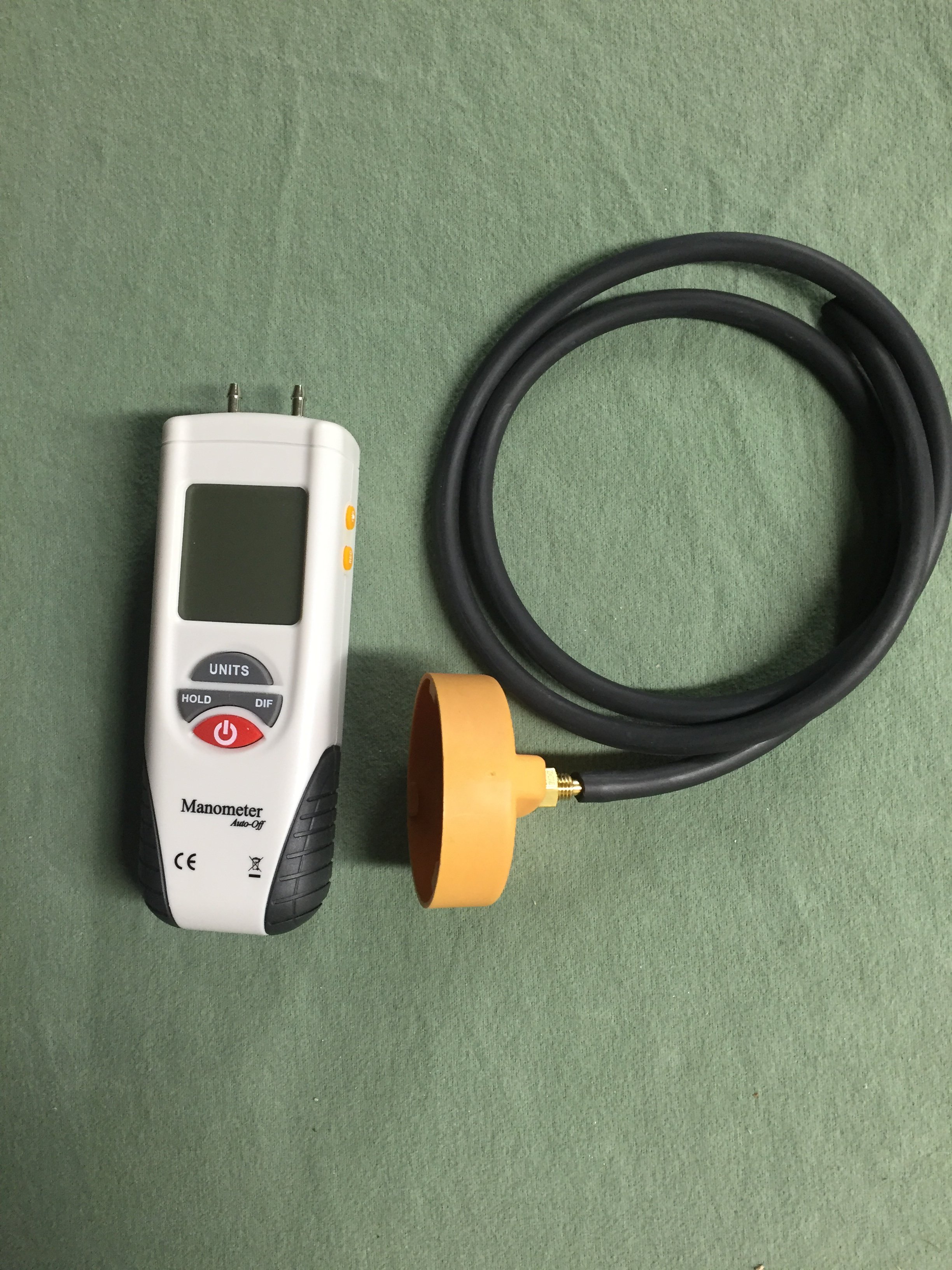
If the oil cap is hard to remove, you have a high vacuum level in the sump, which is bad for a variety of reasons, including lean stalling. The correct way to access the AOS is to fully warm up the engine by driving the car for 10-15 min, then replace the oil cap with the one in the picture above with a hose that connects to the digital manometer. If the vacuum level exceeds 6-7 inches of water vacuum, the AOS is leaking air into the intake system, causing the lean stall conditions. The normal level of vacuum is typically 4-5 inches of water, which is a really weak vacuum level, so it doesn't take much of a leak to cause problems, which is why we always checked every car that passed thru the shop with the manometer.3 points
-
The AOS can either be pin pointed or eliminated by having the car's sump vacuum level checked with a digital manometer (most quality shops have them as the AOS is a perpetual issue; surprise the dealer didn't do this).
 2 points
 -
Welcome to RennTech If you do not have access to a wiring diagram for the vehicle, probably the easiest way to check the ground is to pull the bulb in the light and use a multimeter to check the condition of the ground at the bulb socket.2 points
-
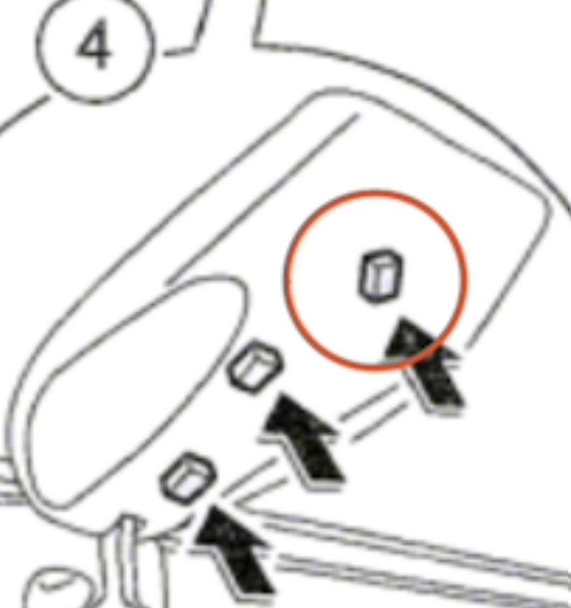
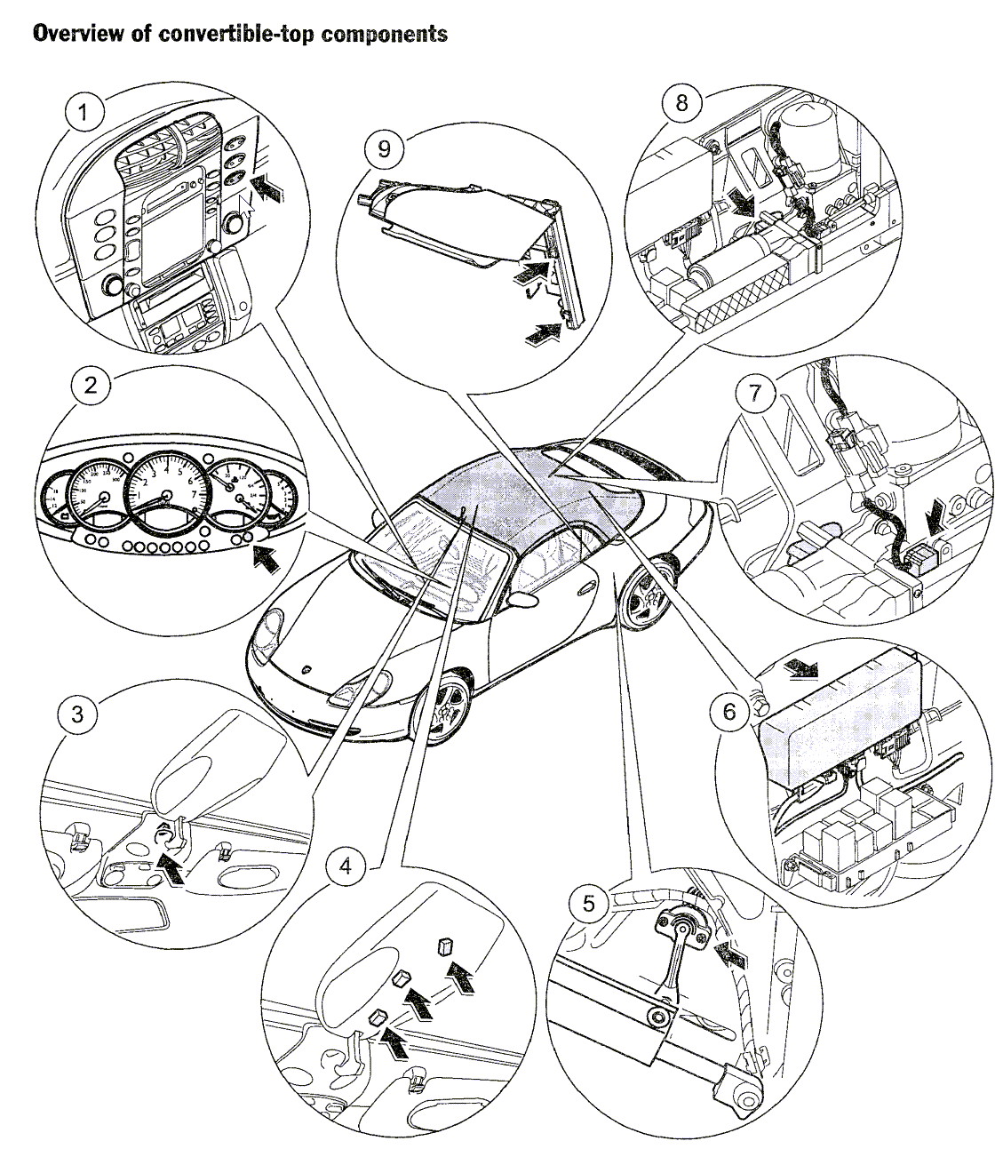
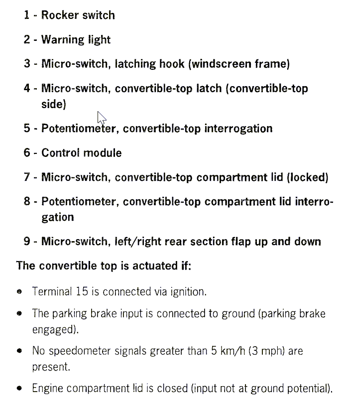
My 2001 C2 top has not worked the entire five years I've owned the car, full saga below.* Without all the back story, here's where I am today. When I click "Calibrate," nothing happens and PIWIS 3 returns "Function inactive, end position not reached." The front latch is reset per the service manual, and the clamshell potentiometer was installed at as close to 6.2k ohms as I can get it (about 6.24-6.26). [I rebuilt this engine in my dining room with my cat, 12,000 miles ago—I may not know what I'm doing, but I can follow directions.] Top is in service position. Actual Values / Input Signals Latch locked Catch not locked Latched unlocked Catch not unlocked (can't be both, right, has to be one or the other?) EDIT: RESOLVED, please see follow up post. Convertible top Convertible top raised Convertible top compartment Convertible top compartment lid unlocked Right side flap up Right side flap not up Right side flap down Right side flap down Left side flap up Left Side flap not up Left side flap down Left side flap down Speed Speed >5 km/h (3 mph) (that's not correct) Handbrake Applied Latching hook Latch hook not actuated Engine-compartment lid Engine-compartment lid closed Convertible top button Close convertible top button actuated Supply voltage 14.45 v Warning light on 36044.3 min (!) Actuation counter 1 1746 Actuation counter 2 65536 Calibration counter 2 Pot 1, convertible top 0.92 v Pot 2 (conv. top compartment. lid) 2.51 v Calibration: Pot 1 val 1 0.80 v Calibration: Pot 1 val 2 1.27 v Calibration: Pot 1 val 3 1.88 v Calibration: Pot 1 val 4 2.29 v Calibration: Pot 1 val 5 2.96 v Calibration: Pot 1 val 6 3.22 v Calibration: Pot 2 val 1 1.55 v Calibration: Pot 2 val 2 1.82 v Calibration: Pot 2 val 3 2.00 Calibration: Pot 2 val 4 2.71 These aren't even actual calibration values, are they, they're stored values from the last time it successfully calibrated. It's my latch isn't it. There's a microswitch I've overlooked, a stupid simple on off switch, and because of that, it never starts the calibration process. Guess I'm going out there one more time this weekend and taking that off again. Insight invited, thanks for letting me ramble. 😄 Keith *The Complete Saga I bought the car like this in January of 2001. Tip cab with a top that had been manually put up via emergency procedure. Dash light for the top was on. I found a matching hardtop an hour away that same week, manually put the top down, slapped the hardtop on, and drove it. Turns out, the left rear window regulator had failed and someone had manually pulled it up (the motor was missing) and then drove a drywall screw through the regulator frame close enough under the bottom of the window bracket that the window stayed up. I rebuilt both rear window regulators and in October of 2021, started working on the top. I probably didn't reset the latch correctly at that time, or the clamshell pot. Still, I told Durametric to calibrate and it started to. When the top moved doubt 1/2 way up, I could hear the pump motor straining and—since the rear interior panels were still off—I took a look: both hydraulic pistons were jetting fluid down the rain drains. I put the hard top back on. Then the engine failed, then (unrelated) I moved, and I spent all of 2023 rebuilding it. July, 2024, I sent two cores to Cab Hydraulics in Sarasota to rebuild. Put them in, new hoses too, and this time I reset the latch and the clamshell pot correctly. I think. But there was no longer a top warning light on on the cluster. I told Durametric to calibrate it, and it wouldn't. Opened a dialogue with the developers, sent them logs they asked for, did everything the guy said, and the last I heard was that maybe their software wouldn't calibrate it unless it was in an error state. Then (not their fault) I took a job and started the process of moving. Hard top went back on. July 2026, time to get back to it. I knew I was going to have to have access to PIWIS, so I followed that thread on some other forum ("under $75") and got the image running on my shop computer. Which, I understand, isn't the same as pulling up to the dealer, so I'm aware that's a possible failure point. I 100% believe the latch and clamshell pot to be correctly reset now. No dash light. When I click "Calibrate," nothing happens and PIWIS 3 returns "Function inactive, end position not reached."1 point
-
Try 96391 point
-
Try 30901 point
-
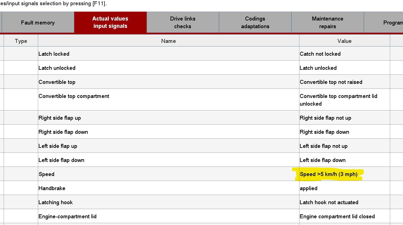
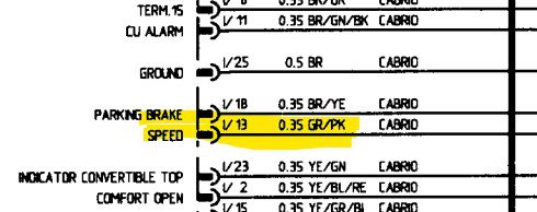
My convertible top has never worked so today I started testing all systems. I reset the lid potentiometer to 6.2k, manually opened the front latch and told the PIWIS to perform a calibration. The windows begin to lower but they stop moving after a second, triggering the dreaded "Function inactive, end position not reached" error. I tested all of the microswitches and got good results. I moved on to the "Drive links checks" and can move everything (except for the side flaps) but not for more than a second before receiving "Function inactive...etc" errors every time. For some reason the convertible top ECU is receiving an actual speed value of "Speed >5km/h (3mph)". (Highlighted in yellow on the attached screen grab). Is that enough to halt every attempt to perform calibration or drive links checks? I found a DIY from Loren (see below) that said to cut the GREY/ PINK wire leading to the top ECU if you want to eliminate the speed check for top operation. I checked it against the 2000 wiring diagram and made sure it was pin 13 on connector 1. CUT! And there was no change in the Speed value. Still reading above 5km/h - 3mph with the car standing still, parking brake on. Is there something else that will cause "drive link checks" or calibration to last only a moment before returning a "Function inactive, end position not reached" error? Thanks! )
1 point
-
I have a '99 Carrera and I'm struggling here... I just replaced the gas filler vent valve and I was still having trouble filling. I did a search and read about re-installing the reed sensor. I pulled the fender liner and vent valve, but I can find the reed sensor anywhere. Where is the connector for the sensor? There are no loose wires anywhere to be found and I didn't tuck away or see anything dangling when I removed the original vent valve. I find this so strange.1 point
-
Thanks, Loren—I had not noticed there are three microswitches in the latch, I'll look at that 3rd one next.
1 point
-
Must not be seeing one of the microswitches (dirty, misaligned, or broken).
1 point
-
Try 64101 point
-
Try 48971 point
-
Try 50161 point
-
Try 05981 point
-
1 point
-
The easiest and probably cheapest way as well is to add a small amount of coolant compatible UV dye to the system and run the engine for a bit. The dye will leave a highly visible (with a UV light source) trail to exactly where it is coming from. We use this technique regularly in the shop to trace difficult leak sources.1 point
-
Many times the servo is not bad but the foam from the flaps has deteriorated and jammed their movement. I would check that first then rest the codes and test before actually replacing any servos.
1 point
-
Try 54301 point
-
Porsche only - find a donor car to get them from.1 point
-
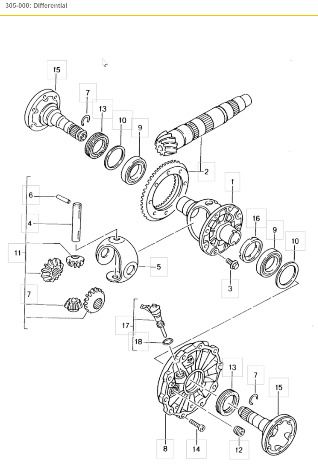
Item 13 is the radial shaft seal. (click the image to enlarge it)
1 point
-
It that a plug or plastic pop rivet? I am only finding the plastic rivet.1 point
-
Remember the new ride height will be 10 mm lower than the stock height - plus the springs, struts and swaybars will all be firmer than the stock items. As I said before another option PSS-9 (adjustable) Coilovers - likely easier to find as either OEM or aftermarket.1 point
-
1 point
-
I put it in my 2004 Turbo Cab and it works great. plug and play though playing content through your iphone is not as loud as the normal stereo... you don't have to purchase the NAV card; you can use apple carplay... works a treat. Hope that helps.1 point
-
See if any of the fault codes have changed. If not, then I would still go the path based on the FRAU readings.1 point
-
Still Fighting the misfire, local shop checked some things and found that my battery cable, the bolt that goes through the fire wall and starter / alternator cable needs to be replaced ( starter also ) before they go farther with diagnostics. $720 for diagnostics and $4000 to replace above parts (parts included) Payed for diagnostics and did all work myself. Still same problem - misfire on cyl-1 and sometimes on 3 ( misfire on 4 was just loose coil from my sloppy install ) work in progress 😞1 point
-
I replaced the crankshaft position sensor and so far, seems to have fixed the problem. The engine has started a lot quicker when cold and when warm. One of the easier jobs I have done on this vehicle. Although I do have one of these lifts I purchased about 8 years ago, it sure helps a lot (made in Germany): Scissor lifts WWW.TWINBUSCH.DE Scissor lifts1 point
-
Try 10981 point
-
Just to close this thread. The alternator died sitting on a shelf for 6 weeks while other work was being done. A new alternator fixed my issues. I hate when something goes wrong simultaneous with other issues.1 point
-
1 point
-
Try 97861 point
-
We have used them here in the US for years at MUCH colder temperature's than you get without ANY issues. Put on the adaptor, add external magnets such as the Filter Mag, and enjoy both better filtration and peace of mind.......1 point
-
Sorry I have not replied. I did not buy the Cayenne it belongs to a friend of mine and I enjoy working on them when I have time so I spend a few days a week fixing stuff. It been fund and I love finding something that is bad from either age or the last repairman messed something up. so far I have replaced both valve cover seals with the cam actuator seals and spark plug tube seals and new spark plugs. I also replaced the vacuum pump and fixed the power brake vacuum hose that was cracked on both ends, I also replaced the purge valve. I also made a new vacuum line from the oil air separator to front timing chain cover out of copper pipe with rubber ends. I was very pleased to see how nice the motor runs now. I also replace the rear hatch actuator to unlock the rear hatch before you would hit the button but it would not unlock you had to use your finger to manually unlock it from the inside. that's fixed now. Right now I have the head liner and the sunshade off and getting ready to clean the old headliner before I put in the headliner but, before I put back the headliner I'm going to replace both struts for the rear hatch, the glass does not stay up at all and the hatch does stay up but it slams when its closing. I also fixed the drivers seat back cover that kept coming off, I ran a screws 1/4 through bottom of the back cover to hold it to the seat. I have to do the same thing to the passenger side seat too. once I have everything fixed inside the car I need to see what the oil leak it has/had is coming from it could be from old valvecover seals that I replaced or the transmission is leaking. when he first dropped off the car the oil leak was massive and now after the work I have done to the car the oil stain is a drop so that may be fixed, but I need to see and make sure. Oh I'm having a problem finding the struts for the hatch the car has the power liftgate, I find the struts for the glass but I can't find for the power lift gate, does it now use struts for the hatch on the power lift get?1 point
-
You need a Porsche specific scan tool to see the faults, something like the Durametric system or a PIWIS system, no other scan tools will be able to see the faults.1 point
-
If you get a honk it means you have at least one zone open or one (or more) fault codes. You will need a Porsche compatible scanner to get the fault code and report it here. It should narrow down exactly where the problem(s) are.1 point
-
Try 53501 point
-
Look, diagnostics is all about isolating the problem(s) so they can be addressed. With the sensor disconnected, you are only looking at the sensor, everything else is out of the equation. Same thing when you disconnect the sensor and the connector at the DME, then you are only looking at the harness. With the sensor connected to the harness, but the harness disconnected from the DME, you are looking at what the DME is seeing. You need to go one step at a time, there are no short cuts. Porsche tends to collect various grounds to specific ground points, mostly as a matter of convenience and reducing wire runs rather than running them all to one point. All the cars have a multitude of grounding points in them as noted in the wiring diagrams.1 point
-
Try 94321 point
-
I'm heading to the track for the first time and Shenandoah circuit at Summit Point apparently has a little crest where some people catch air. I don't want the rollover bars to scare the crap out of me while on the track. Any ideas?1 point
-
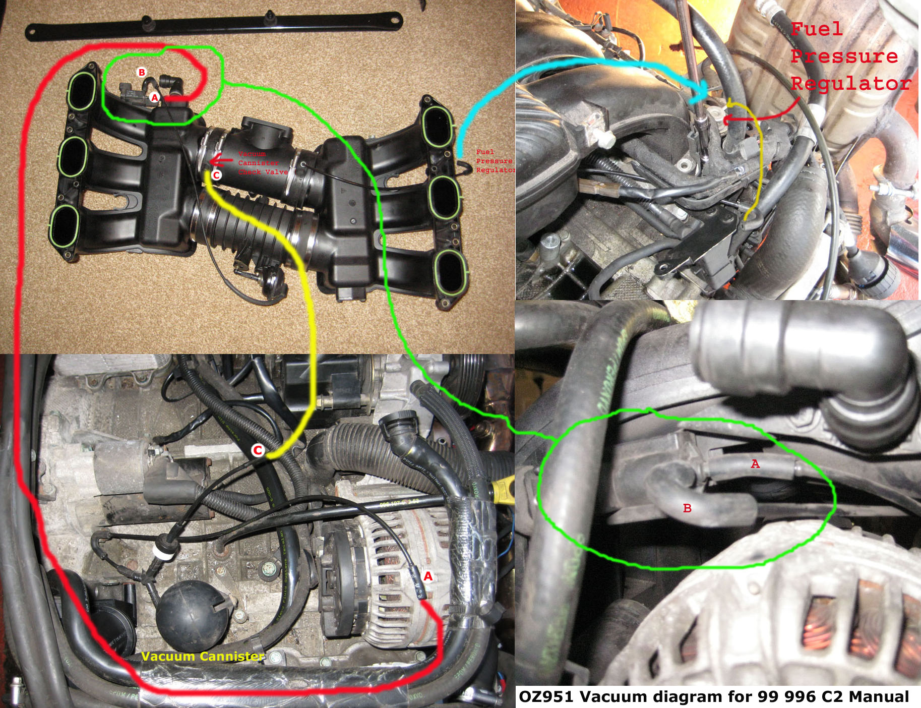
In case someone searches for vacuum line routing in the future
1 point
-
P0441 code is EVAP purge valve, alongside the drive side intake manifold tubes. P2281 Code is most likely an air leak between the MAF and the throttle body, the code generally means that the powertrain control module (PCM) has detected a degree of airflow at the mass airflow (MAF) sensor which does not exist at the throttle body.1 point
-
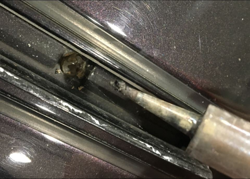
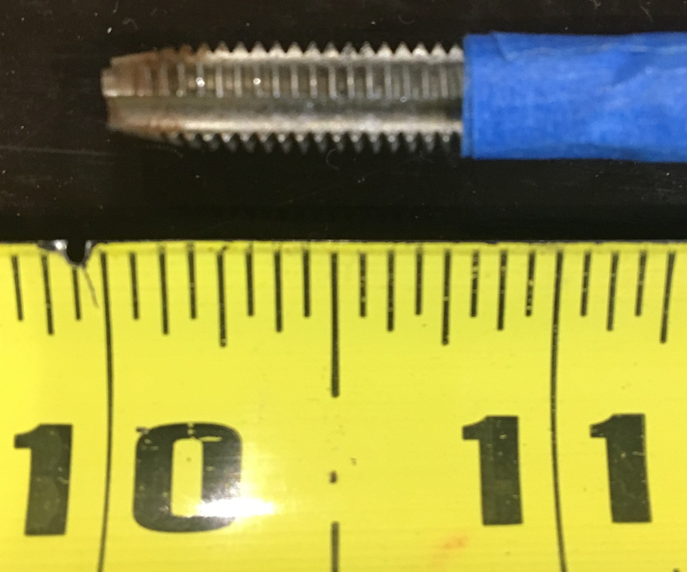
On my 2000 C4 I was lucky enough to have nylon screws. They broke of course, but drilling and tapping was easy with a few tricks and observations: Using a soldiering iron to melt a hole through the center of the nylon screw makes drilling MUCH easier Used a 3/16" drill bit to remove the majority of the nylon then used a 6mm x 1.0 to clean the threads Plunge depth is 3/4" Use a "bottom" tap rather than a "tapered" tap so you clean threads quickly and without significant insertion.
1 point
-
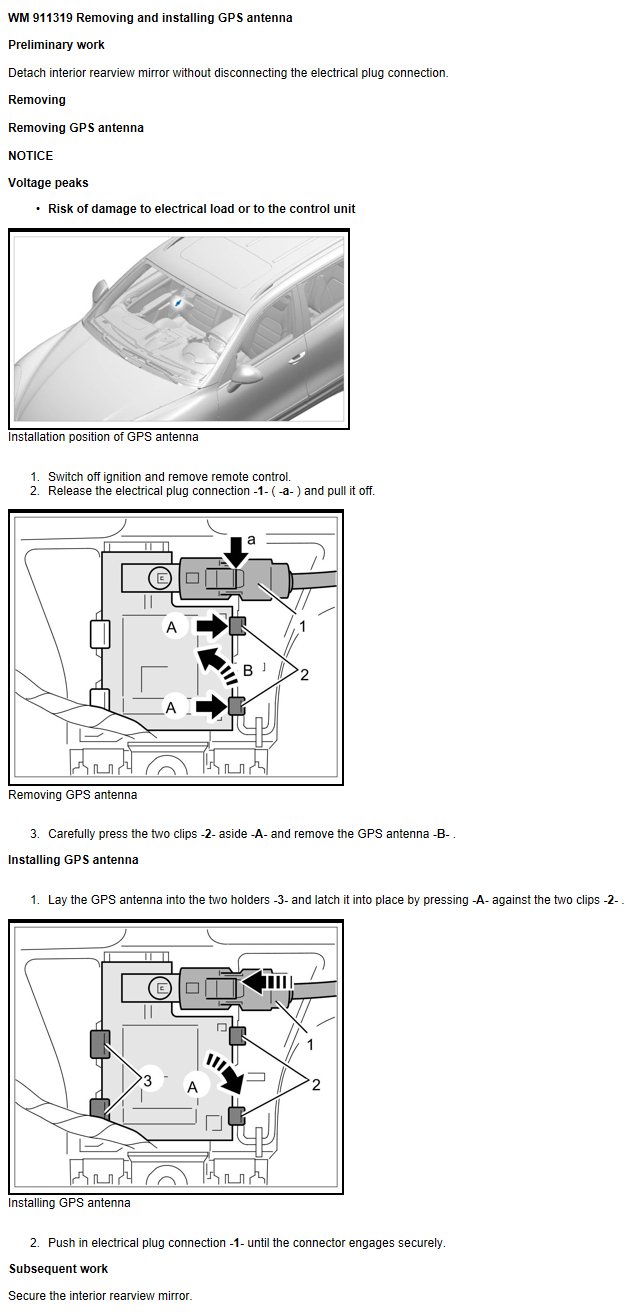
Osunick, Your GPS antenna is located behind the rearview mirror. Hope this helps.
1 point
-
Try 65131 point
-
P0455 Leakage in fuel tank system Diagnostic conditions D Vehicle speed = 0 km/h D Engine speed = 0 rpm D Correction factor, height > 0.73 D Coolant temperature upon starting the engine may be no more than 6.8 K above ambient temperature D Coolant temperature when engine starts > 3.8 °C D Period for which the engine needs to have been running before ignition is switched off > 20 minutes D Ignition has been switched off for at least 10 seconds. D Ambient temperature 4 … 35.3 °C D Active charcoal filter load < 3 for minor leak D Fuel tank fuel level 10 … 54 litres D Battery positive voltage 11.02 ... 14.5 V D No fuel tank filling D No faults detected for ambient pressure sensor, coolant temperature sensor, vehicle speed sensor D No output stage faults detected for DMTL pump motor, DMTL switch-over valves and tank vent D No fault detected for tank vent (flow) E The diagnostic conditions can also be established using the PIWIS Tester via the short test "tank leakage test". After the test has begun, the ignition must be switched off. F NOTE E In this context, please also observe the function description. Possible fault causes E Tank cap not closed correctly, leaking or missing E Purge air line leaking E Tank vent leaking E DMTL (Tank Leakage Diagnostics Module) leaking E Leakage in fuel tank system Page 140 of 398 07/20/2006 Function description Tank leakage test/DMTL – Tank Leakage Diagnostics Module F Note E The tank leakage test is performed only on USA vehicles. Construction of the tank leakage diagnostics module: The diagnostics module consists of an electric motor with a small air pump, switch-over valves and a reference nozzle. In addition, the modul is heated so as to prevent the forming of condensation and ice. Procedure of the function: E The pump is operated via an electric motor and conveys air through the reference leak. The power consumed during this process is determined. E The switch-over valve switches and the air current is now directed into the fuel tank. The power consumed during this process is also determined. After a waiting period dependent on the fuel tank fuel level, it must be at least as high as the power consumption was during the reference leak test if the tank system is leak-free. E The system is identified to by leaking if the power consumption is lower during the actual leakage test as it was during the reference leak test. E An evaluation of the power consumption levels when the pump is started and after the switch-over valve has switched serves to identify faults within the tank leakage diagnostic module (e.g. pump blocked, motor spins at idle speed, valve does not switch etc.). E The diagnosis of heating, motor and switch-over valve is performed via the output stage of the DME control module. P0456 Leakage in fuel tank system Diagnostic conditions D Vehicle speed = 0 km/h D Engine speed = 0 rpm D Correction factor, height > 0.73 D Coolant temperature upon starting the engine may be no more than 6.8 K above ambient temperature D Coolant temperature when engine starts > 3.8 °C D Period for which the engine needs to have been running before ignition is switched off > 20 minutes D Ignition has been switched off for at least 10 seconds. D Ambient temperature 4 … 35.3 °C D Active charcoal filter load < 3 for minor leak D Fuel tank fuel level 10 … 54 litres D Battery positive voltage 11.02 ... 14.5 V D No fuel tank filling D No faults detected for ambient pressure sensor, coolant temperature sensor, vehicle speed sensor D No output stage faults detected for DMTL pump motor, DMTL switch-over valves and tank vent D No fault detected for tank vent (flow) E The diagnostic conditions can also be established using the PIWIS Tester via the short test "tank leakage test". After the test has begun, the ignition must be switched off. F NOTE E In this context, please also observe the function description. Possible fault causes E Tank cap not closed correctly, leaking or missing E Purge air line leaking E Tank vent leaking E DMTL (Tank Leakage Diagnostics Module) leaking E Leakage in fuel tank system Function description Tank leakage test/DMTL – Tank Leakage Diagnostics Module F Note E The tank leakage test is performed only on USA vehicles. Construction of the tank leakage diagnostics module: The diagnostics module consists of an electric motor with a small air pump, switch-over valves and a reference nozzle. In addition, the modul is heated so as to prevent the forming of condensation and ice. Procedure of the function: E The pump is operated via an electric motor and conveys air through the reference leak. The power consumed during this process is determined. E The switch-over valve switches and the air current is now directed into the fuel tank. The power consumed during this process is also determined. After a waiting period dependent on the fuel tank fuel level, it must be at least as high as the power consumption was during the reference leak test if the tank system is leak-free. E The system is identified to by leaking if the power consumption is lower during the actual leakage test as it was during the reference leak test. E An evaluation of the power consumption levels when the pump is started and after the switch-over valve has switched serves to identify faults within the tank leakage diagnostic module (e.g. pump blocked, motor spins at idle speed, valve does not switch etc.). E The diagnosis of heating, motor and switch-over valve is performed via the output stage of the DME control module.1 point
-
Although embarrassing to air my mistake, I thought I would post this in hopes I might save someone else from the same problem: If you have adjustable coilover shocks, do not attempt to change your car's ride height unless you are doing it while corner balancing with scales. I rationalized that if I set the ride height using the factory measuring method (documented in multiple places on this site) I would get "close enough" to a balanced car for a 996 that isn't tracked. Wrong. I worked on a level floor, with a full tank of gas (per spec), new tires with factory-recommended tire pressures, using the factory-recommended ride height measurement points, drove the car a few yards after each change to settle the suspension, and after a lot of hard work I was dead on with each of the four measurements. A local indie shop, not really performance oriented, vetted my approach and said it should be fine, it's what they would do. Even after a perfect-to-the-spec alignment this morning the car pulls to the right, enough at 40 mph with hands off the wheel to change lanes in less than 50 yards. My effort was wasted and I'm out the cost of that alignment. The car goes in for a pro corner balance to correct the issue and I'll end up paying for another alignment. Lesson learned. In truth, the effort wasn't entirely wasted because I learned about the stiffness of the chassis, how even a minute change of 1mm in shock adjustment can affect all four wheels, and how each of the wheels is affected. Dialing in the ride height was a PITA but a learning experience that I believe transfers to doing a corner balance. If you install height-adjustable shocks, you must corner balance for optimal handling even if your car is a daily driver and not tracked. Bless you suspension techs who do corner balancing for a living!1 point
-
I think this will do it. Good luck. DC Porsche 997 PCM Removal.pdf1 point
-
Well... I replaced the hinge on the center console today. After reading all that was available, I went with doing it without removing a lot of stuff like the TSB. All done sitting in the back. Not hard to do. You will have to take a hack saw blade and cut off the unbroken hinge collar, then file both spots till they are flat. The U shaped rivet supports take a needle nose plier to put in place. Knock the shaft out from right to left. Vacuum the aluminum curlies out after you do the drilling.1 point
-
Yes that tube goes to the resonance flap. It's probably a really long tube right? That's the one that goes to the rear of the engine (front of car). From my above post: "In the diagram link below, the tubes you are talking about is #19, which goes into #21 (another hose) which then goes into the resonance flap: http://www.autoatlan...9-05/107-10.php" Yes the DIY link I posted has the procedure you need to remove the throttle body and t-plenum so you can reach behind the rear intake crossover and reconnect a new tube from the resonance flap to the change over valve in the position you indicate (hose/tube p/n 00004320501 qty 1) You might need a extendable mirror to see it.1 point
-
Hi, yes Mobil 1 5w-50 is the only SAE50 viscosity lubricant Approved by Porsche. It is an excellent lubricant with a long history. It ia available in most Countries except the USA Mixing most Mobil 1 products to achieve a "supplementary" viscosity can be done without the risk of loosing the benefits of the overall base fluid/additive package There are two exceptions to this however. M1 0w-40 and M1 Turbo Diesel Truck 5w-40 (non Approved) should not be mixed with other Mobil 1 lubricants if you wish to retain their unique and quite sophisticated formulation I use the "parent" of M1 TDT 5w-40 - it is a Commercial lubricant called Delvac 1 5w-40 Regards Doug1 point