Welcome to RennTech.org Community, Guest
There are many great features available to you once you register at RennTech.org
You are free to view posts here, but you must log in to reply to existing posts, or to start your own new topic. Like most online communities, there are costs involved to maintain a site like this - so we encourage our members to subscribe or donate. All subscriptions and donations go to the costs operating and maintaining this site. We prefer that guests take part in our community and we offer a lot in return to those willing to join our corner of the Porsche world. This site is 99 percent member supported (less than 1 percent comes from advertising) - so please consider an annual subscription or donation to keep this site running.
Here are some of the features available - once you subscribe RennTech.org
- View Classified Ads
- DIY Tutorials
- Porsche TSB Listings (limited)
- VIN Decoder
- Special Offers
- Paint Codes
- Registry
- Videos System
- View Reviews
- and get rid of this welcome message
It takes just a few minutes to register, and it's quality Porsche information at a low cost.
Contributing Members also get these additional benefits:
(you become a Contributing Member by subscribing or donating money to the operation of this site)
- No ads - advertisements are removed
- Access the Contributors Only Forum
- Contributing Members Only Downloads
- Send attachments with PMs
- All image/file storage limits are substantially increased for all Contributing Members
- Option Codes Lookup
- VIN Option Lookups (limited)
Leaderboard
-0001-0001.thumb.png.17f5bb25bf8ec261a17c21e6321c8492.png)


Popular Content
Showing content with the highest reputation since 07/08/2025 in Posts
-
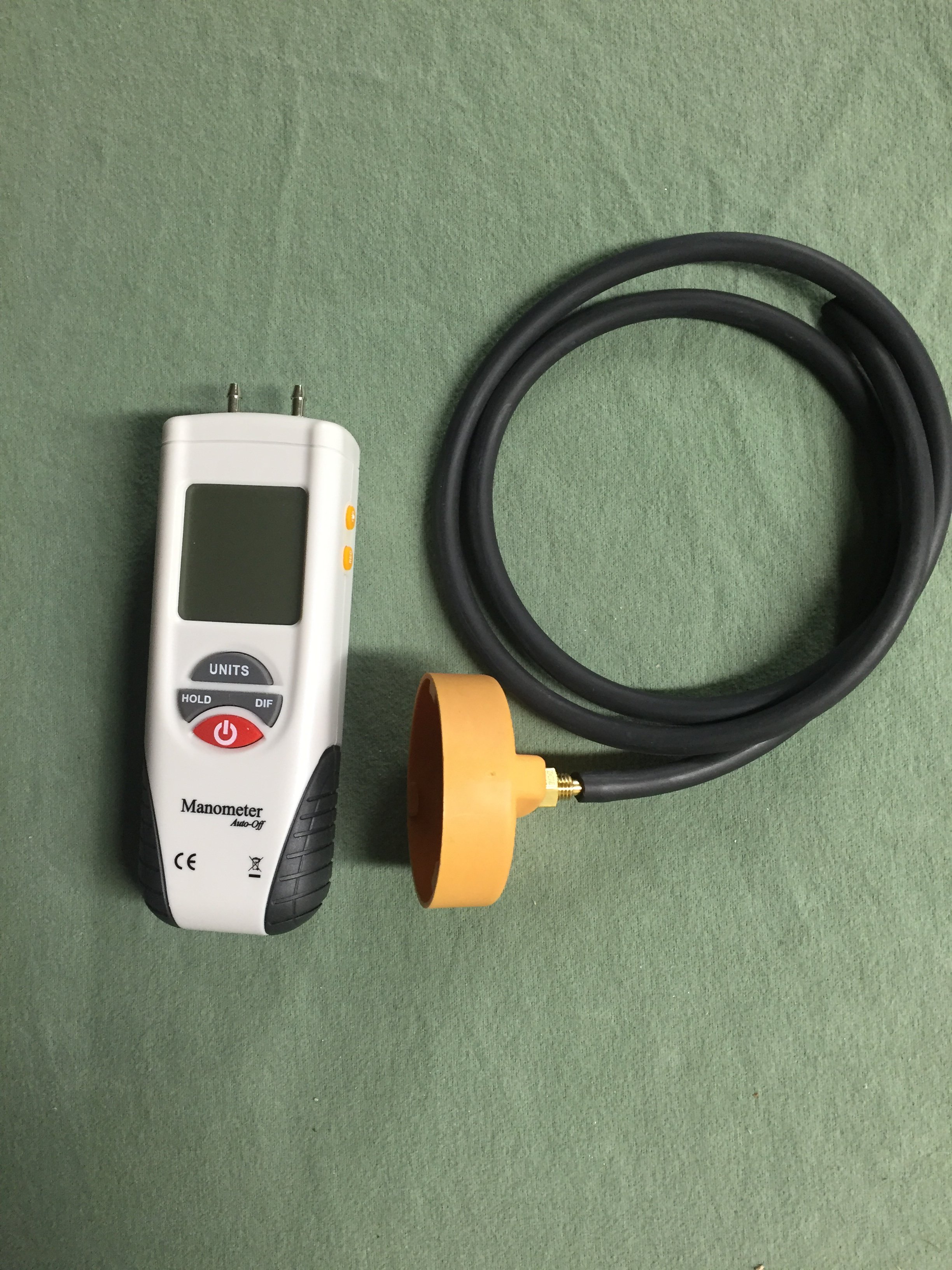
If the oil cap is hard to remove, you have a high vacuum level in the sump, which is bad for a variety of reasons, including lean stalling. The correct way to access the AOS is to fully warm up the engine by driving the car for 10-15 min, then replace the oil cap with the one in the picture above with a hose that connects to the digital manometer. If the vacuum level exceeds 6-7 inches of water vacuum, the AOS is leaking air into the intake system, causing the lean stall conditions. The normal level of vacuum is typically 4-5 inches of water, which is a really weak vacuum level, so it doesn't take much of a leak to cause problems, which is why we always checked every car that passed thru the shop with the manometer.3 points
-
The AOS can either be pin pointed or eliminated by having the car's sump vacuum level checked with a digital manometer (most quality shops have them as the AOS is a perpetual issue; surprise the dealer didn't do this).
 2 points
 -
Welcome to RennTech If you do not have access to a wiring diagram for the vehicle, probably the easiest way to check the ground is to pull the bulb in the light and use a multimeter to check the condition of the ground at the bulb socket.2 points
-
We have used them here in the US for years at MUCH colder temperature's than you get without ANY issues. Put on the adaptor, add external magnets such as the Filter Mag, and enjoy both better filtration and peace of mind.......2 points
-
Welcome to RennTech The factory radio had a ground wire that had to be attached to the car's chassis under the dash as a simple anti theft device. If that ground is not there, the immobilizer will prevent the car from starting.2 points
-
1 point
-
Many times the servo is not bad but the foam from the flaps has deteriorated and jammed their movement. I would check that first then rest the codes and test before actually replacing any servos.
1 point
-
Try 96411 point
-
Try 54301 point
-
Porsche only - find a donor car to get them from.1 point
-
Try 76821 point
-
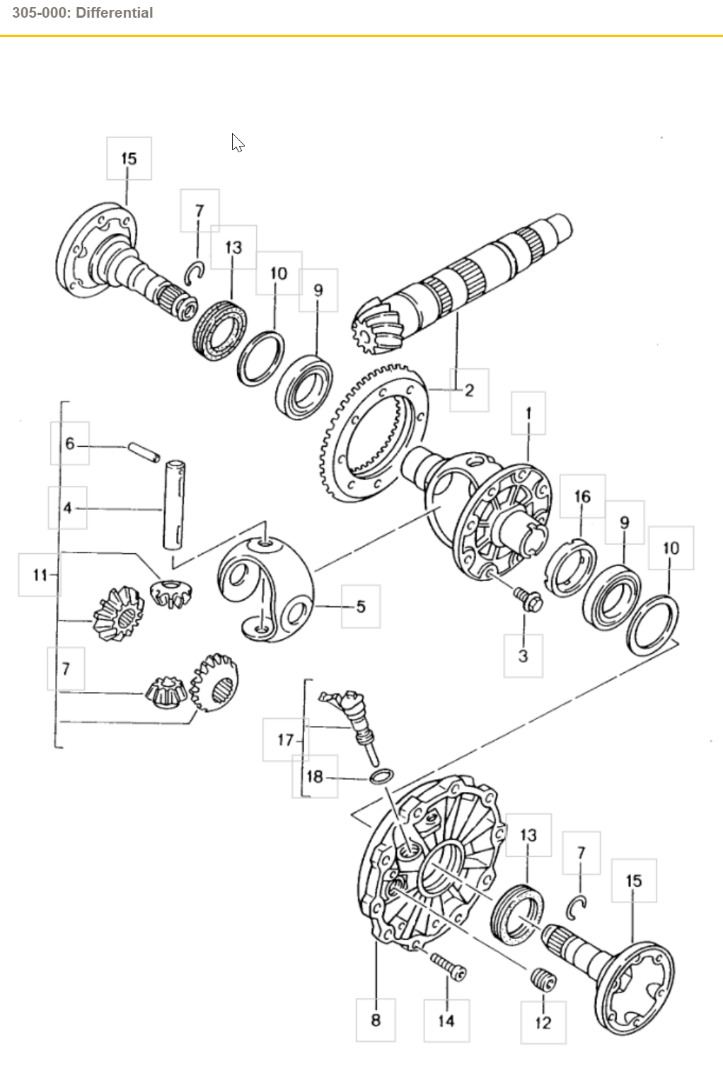
Item 13 is the radial shaft seal. (click the image to enlarge it)
1 point
-
I have a '99 Carrera and I'm struggling here... I just replaced the gas filler vent valve and I was still having trouble filling. I did a search and read about re-installing the reed sensor. I pulled the fender liner and vent valve, but I can find the reed sensor anywhere. Where is the connector for the sensor? There are no loose wires anywhere to be found and I didn't tuck away or see anything dangling when I removed the original vent valve. I find this so strange.1 point
-
See if any of the fault codes have changed. If not, then I would still go the path based on the FRAU readings.1 point
-
P2189 Lambda control adaptation FRAU (lower load range) (FRAU > 0.7) - below limit value Possible fault causes - Incorrect main filling signal from hot-film mass air flow meter - Fuel pressure too high - Injection valve faulty (dripping) - Tank vent faulty (does not close completely) P2189 Lambda control adaptation FRAU (lower load range) (FRAU > 1.3) - above limit value Possible fault causes - Intake system leaking (secondary air) - Incorrect main filling signal from hot-film mass air flow meter - Leak in exhaust system - Fuel pressure too low - Fuel injector faulty (stuck) - Fuel pump delivery too low P2187 Lambda control adaptation FRAU (lower load range) (FRAU > 0.7) - below limit value Possible fault causes - Incorrect main filling signal from hot-film mass air flow meter - Fuel pressure too high - Injection valve faulty (dripping) - Tank vent faulty (does not close completely) P2187 Lambda control adaptation FRAU (lower load range) (FRAU > 1.3) - below limit value Possible fault causes - Intake system leaking (secondary air) - Incorrect main filling signal from hot-film mass air flow meter - Leak in exhaust system - Fuel pressure too low - Fuel injector faulty (stuck) - Fuel pump delivery too low1 point
-
I replaced the crankshaft position sensor and so far, seems to have fixed the problem. The engine has started a lot quicker when cold and when warm. One of the easier jobs I have done on this vehicle. Although I do have one of these lifts I purchased about 8 years ago, it sure helps a lot (made in Germany): Scissor lifts WWW.TWINBUSCH.DE Scissor lifts1 point
-
Try 10981 point
-
Try 89641 point
-
Non, push down with one hand, squeeze the ribbed bottom ring with the other hand and pull up, this is not as easy as it looks, succes.1 point
-
Your alternator is not functioning, running you should have 14.5V DC. Pull the alternator, check the wiring connections to be sure they are tight and seated, if they are you are in the market for a voltage regulator..........1 point
-
What are your voltages? Resting, idling, driving above 2000rpm? There are gizmos to help with this monitoring - Antigravity Batteries has a battery tracker. Others plug into the cigarette lighter. Do you have any codes (can be read with Durametric and other (OBDII) readers)? I've read stories on Rennlist about induced electrical noise in the sound system even when the sound system is not turned on. Might your alternator be damaged or no longer have a high quality ground? Could the noise be mechanical (transmitted noise)? You did change pulleys. Run the car a few minutes without the serpentine belt and see if the noise is reproduced.1 point
-
N 104 707 03 round hd. screw US MSRP $1.91 (each)1 point
-
Try 45051 point
-
Do this someplace safe... Put in Neutral and see if the noise continues or not. If it does not continue then it is likely in the drivetrain (transmission, transfer case, driveshaft, rear end}. If it does continue then it is likely in the running gear (wheel bearing, axle shaft, or even warped brake discs).1 point
-
Try 07581 point
-
Try 70691 point
-
Try 84581 point
-
Perhaps - what is more important is the wheel offset. The fronts should be fine as both Boxster and 996 use 50 mm offset on 17 inch front wheels. The rear wheels for Boxster are 50 mm standard with an option of 55 mm. With the 55 mm offset wheel you are not allowed to install chains as they will damage the fender. So just be careful of offset for your uses.1 point
-
Try 54251 point
-
I do not, we normally stock a variety of wire sizes and colors, heat shrink tubing, connectors, zip ties, and the like that we source from a local electrical vendor, but you can find similar supplies from multiple sources like WireCare.com | Your Local Cable Management Superstore! WWW.WIRECARE.COM WireCare is your online wire & cable management superstore. We have what you need for connecting, harnessing, & beautifying all of your electrical projects. We carry the highest quality... .1 point
-
Here is the documentation from the Porsche DME manual P0327 210 Knock sensor 1 - below limit Diagnosis conditions • Engine speed more than 3600 rpm • Engine load greater than 45 % Possible fault cause ♦ Break in wiring or short to ground ♦ Contact corrosion on the connector ♦ Knock sensor loose ♦ Short circuit to B+ ♦ Knock sensor ♦ When a fault is stored, the ignition angle is retarded for all cylinders in the range in which knock control is active. ♦ Knock control adaptation is inactive. ♦ If knock control becomes active here, this may indicate engine damage (increased noise level) Affected terminals Terminal III/49 and III/50 Diagnosis/troubleshooting1 point
-
Try 67041 point
-
If you get a honk it means you have at least one zone open or one (or more) fault codes. You will need a Porsche compatible scanner to get the fault code and report it here. It should narrow down exactly where the problem(s) are.1 point
-
Because it is a 2005 engine, it would most likely have the oversized third generation IMS bearing in it, which means it cannot be removed without total disassembly of the engine because it will not fit through the opening in the engine cases. One way to know for sure would be to pull the trans, clutch and flywheel off and look at the nut on the IMS bearing center bolt; if it is 22 MM, you have the oversized bearing, which was the only one to use that large a nut.1 point
-
Try 94321 point
-
I'm heading to the track for the first time and Shenandoah circuit at Summit Point apparently has a little crest where some people catch air. I don't want the rollover bars to scare the crap out of me while on the track. Any ideas?1 point
-
P0441 code is EVAP purge valve, alongside the drive side intake manifold tubes. P2281 Code is most likely an air leak between the MAF and the throttle body, the code generally means that the powertrain control module (PCM) has detected a degree of airflow at the mass airflow (MAF) sensor which does not exist at the throttle body.1 point
-
We did this for all Carrera variations so it's time we added for the Boxster's too. Measure the position of the logo with a measuring tape according to the model variant and affix it to the rear lid. Logo Boxster -- 3 A dimension X = 285 mm and Y = 45 mm Logo Boxster S -- 3 A in connection with the letter S dimension X = 245 mm and Y = 45 mm Logo S -- 3 B dimension Z = 20 mm and V = 40 mm
1 point
-
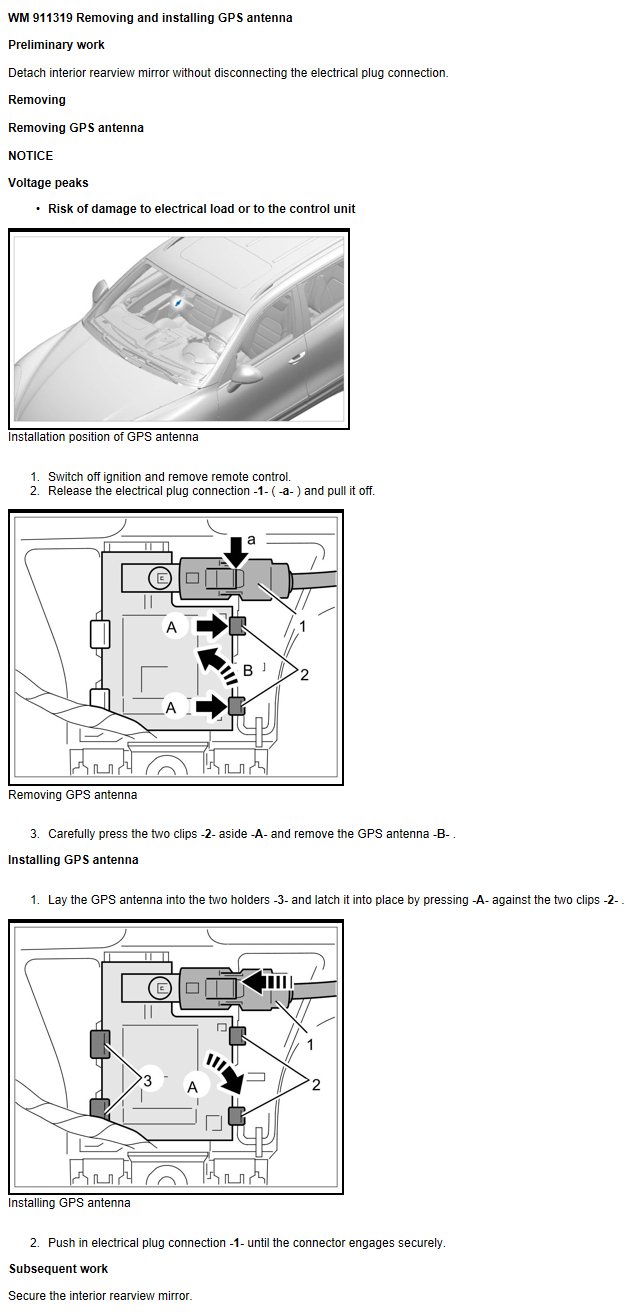
Osunick, Your GPS antenna is located behind the rearview mirror. Hope this helps.
1 point
-
2001 C4 Cab. 58k miles. I have this exact problem, ticking that happens at idle, but slightest depression of clutch pedal makes it stop. Got new clutch 4 months 4 k miles ago. The noise started a few weeks ago,. Any idea how in the world the clutch master could be making that noise? Reluctant to replace without seeing how it could be the problem. Thanks.1 point
-
BTW fixed a similar "rise" in my rear seat area recently. Drop the back seats and remove the two phillips screws. I bet the tab on the rear cover under the carpet area has broken off. That causes the rear piece to flex up. I removed all the screws from the piece and took it out. Used e6000 glue and glued a washer to the broken plastic (and remaining piece I found). Allowed the back to be bolted in nice and flush.1 point
-
1 point
-
For the fingertip test: Turning on the A/C to cause the low speed relays to click on and off will only happen when the coolant temperature is below 206 degrees Farenheit. If the coolant temperature is above 206 degrees, but below 215, the low speed fans will turn on (and the low speed relay will click) without pressing the A/C button on. Regards, Maurice.1 point
-
You can always click the green up arrow to raise logray's reputation... just pick one of his posts here and click the green arrow.1 point
-
Changed the master clutch cylinder and the noise is gone. Thanks for all of your comments. Carrera3.2, When I did the clutch/flywheel, I also replaced the: - IMS bearing and flange with LN Engineering upgrade - All 3 cam chain tensioners - RMS - AOS - Water pump - LN engineering Low Temp thermostat - Slave cylinder - Clutch master cylinder - Sparkplugs and all 6 coil packs - Cardan Shaft (the rubber guibo on my original shaft was cracked) - Coolant reservoir tank and cap - Changed Trans and front diff fluid - Changed oil and filter Hope this helps. If I can think of anything else I did, I'll add to the list. My car drives amazingly well now. Britt1 point
-
I have a '00 C2, 6-speed, Canada version. I keep an eye on the operating temperature, using the OBD hack rather than the gage. In traffic, the car has always run pretty warm, regularly over 100 C in the spring-summer-fall. Last night, it was up over 105 C, and I thought I'd hop out and check to see if the cooling fans had switched to high speed as they are supposed to at this temperature. On the passenger side of the car, the fan was loud and you could feel air being moved. On the driver side, the fan was on but quieter, and less air was moving. Is this normal? If not, can you suggest an explanation? I can imagine losing a fan altogether, but I can't figure out why it would just refuse to switch speeds. TIA, Bruce.1 point
-
I found it......if anyone wants to know....it is directly underneath the driver side intake "plenum".....with the line going into the the intake, right after the throttle body towards the passenger side of the car.1 point
-
I Just replaced one and resoldered the connection. The connection is also mechanically crimped and then soldered. The metal clip is soft and can be uncrimped with a small screw driver and heat from the soldering iron. Be careful not to deform the clip to much, you will have to recrimp and resolder. It was an easy job. Don't for get to "tin" the tip of the soldering iron first. (heat the tip up, melt some solder on and wipe off with a wet sponge). I bough an extra from from Sunset and keep it for the eventual failure of the reight side. This will also be a good time to clean your radiators as well. Good luck J. Greer1 point
-
I'm just toooooo slow. Thanks Loren.1 point
-
I have just completed an OBC and Cruise retrofit to a UK spec 2002 Boxster S (pre facelift). Much of this was possible due to EdBs great work as you will see. Apologies for UK shop names, currency and measurements but this is a direct copy from my post on Boxa.net. Parts List Porsche 996.613.219.10 4 Stalk Steering Wheel Assembly (£80 delivered Porsch-Apart) 999.652.972.40 Cruise Control Connector (£0.29) 999.650.513.40 OBC Connector (£2.86) 999.652.901.22 Pin Connector (9 for Cruise) (£0.27) Unknown Fuse holder connector for 1.00mm2 cable Volkswagen 000 979 009 Wires for OBC Connection (5 Reqd) (£0.99) General 1 off 6mm Eyelet Crimp Connector. 1 off 25mm rubber grommet. PVC coated copper wire (0.5mm2-0.63mm2 conductor area). 4 off 5m runs (Blue, Yellow, Brown, Black) and 1 off 2m (Black) required for Cruise. If you buy another 9 pin connectors and an extra 5 off 0.5 m of wire you can make your own wire runs for the OBC and do away with the VW set. (I used the standard 16/0.2 Equipment Wire from Maplin (£1.10 for 10m) and ran the loom inside the sheathing from standard networking cable. Even with the long wire run the voltage drop is acceptable). Porsche seem to use standard vehicle (9/0.3) cable that you can get from motor accessory shops (not Halfords). I shamelessly used, and totally relied upon, EdB’s Cruise control hack from the RennTech Forum, the Porsche Cars of America OBC hack and various snippets and advice from Boxa.net. I found the pictures from D2 Performance on the Whiteson site particularly useful for fitting the stalk assembly although I had to make allowances for my car being a 2002 Boxster S. I will comment no further on the OBC hack or fitting of the new Stalk Assembly as they are well covered already. Just remember that on a 2002 car without factory OBC you will get full functionality but on the old type of display, i.e. you will not get the dot matrix display as in the Owners Handbook. Just in case you attempt his in isolation you will need to open both rear and front luggage compartments, open the driver’s door, partially open the hood and then disconnect the battery (having left the ignition on for the sake of your ears!) All wires in the Cruise Harness, with the exception of the Fuse Box, need to be terminated with the Porsche crimp connectors above. You will need a decent crimping tool for these little devils. Work from front to back of the car, leaving the connectors at the rear of the car until you have the rest of the loom in place (you can’t stretch wire!) The Cruise Connector from the 4 Stalk Assembly exits to the left of the steering column. One of the wires (Black/Pin no 2) needs to run across to the right and into the back of the fuse box. I found a cable run, just to the right of the steering column and below the instrument cluster, that exits onto the main wiring harness under the dashboard and against the right side of the car above the fuse box. To get access behind the trim to the right of the drivers footwell, pull off the Fuse Box cover and undo the 4 philips head screws. Pull the panel forward at the bottom (lift or remove the floor mat) and it will come away. You have now uncovered the main loom running down to the Fuse Box. The Black lead (Pin No2) from the Cruise connector needs to join the Black wire running to Fuse B7. This is the brake circuit and provides the brake cut off signal to the cruise control logic. At this point you can either splice into the brake wire (easy but less elegant and I was concerned about causing voltage drops in the brake light circuit) or spend ages removing the Fuse Holder Crimp connector from the back of the fuse box and replacing it with another, this time with both cruise and brake wires crimped in. To achieve the latter, spring the front of the fuse box off the bulkhead by lifting the catches that sit behind the, now empty, screw holes. The Fuse Box drops forward so that you can remove the entire second row of fuses by lifting the plastic sprig clips at each end. A white retaining rod runs down inside this fuse matrix and is withdrawn by simply pushing on the narrower end. Remove fuse B7 and use 2 small screwdrivers to release the spring retaining clip from the front of the matrix to release the spade type fuse connector. Cut off and replace with the new connector, crimping in both original brake and new cruise wire. This is undoubtedly the hardest part of the whole job and I must admit that I have simply soldered the new wire to the existing fuse connector until I can get the correct part from Porsche. The remaining cruise wiring harness is made up of 3 wires from the Cruise Connector and 1 wire from the back of the instrument panel (Cruise Indicator). It is strongly recommended to use different colours for all of these wires, as they need to run to the back of the car. The wire to the back of the instrument panel connects into the left hand or White main instrument connector. It needs to slide into pin 17 for the Boxster S. See EdB’s instruction for the Boxster pin assignment. I ran my harness down the right hand side of the car, although, the left side would follow the Porsche convention and be easier if you were running the rear speakers at the same time. It really is personal preference. I ran the harness alongside the single black wire (actually all the same bundle) until reaching the bottom of the driver’s door pillar. I removed the trim running along the sill by using a 5mm hex spanner inserted into the 2 small, blanked off, holes on the inboard side of the trim. Loosen these bolts 2-3 turns and then firmly lift up the trim panel. I had to move the driver’s seat forward and then back to get the spanner into the holes. I ran the cable through the void on the inside of the sill trim, using cable ties to stop rattles. At the rear of the sill I removed the carpeted panel running up to the rollover bar. This was done by undoing the small Philips had screw concealed in the carpet about 4 inches from the floor, and then loosening the small 8mm nut at the top of the panel just behind the rollover bar. By lifting and twisting the bottom towards the driver’s seat, the panel can be removed from the car. The wiring harness was passed up through the plastic sill trim (don’t use the hole for locating the carpeted panel that you have just removed) and around behind the seat belt inertia reel. For the next phase you will need to lift the rear of the hood to provide access to the deck above the engine bay. As part of the preparations for this job you need to have operated the hood mechanism until the tonnaeu cover reaches the highest point. From outside of the car locate the small plastic gutter at the rear of the fabric top and slide it downwards and out of the retaining clips. Next slide your hand under each side of the hood just below and behind the rollover bars to locate the ball connectors on each end of the hood tensioning wire. Simply pop these off the ball joints. The rear of the hood can now be lifted to reveal the top deck. At this point you also need to remove the lining from inside the rear luggage compartment. The simplest way to do this is to remove the bottom first and then the back as they interlock. You can remove only the back but this requires some confidence. To remove the bottom carpet remove the boot catch cover by undoing the 2 philips head screws. Next pop out the 2 press connectors to each side and finally unscrew the connectors above each of the light clusters. To the right of the boot opening you will find 2 plastic slotted connectors, these must be turned a quarter turn to release them. The bottom carpet can now be removed. The back panel is held in place along the top edge by 3 push fit connectors. Simply pull the bottom of the panel forwards, disconnect the lamp and remove the carpet from the car. I had taped a large cable tie to the cruise harness and managed to feed this from inside of the car, along just inboard of the rollover bar and out under the lining of the hood stowage. I ran the wires under the soundproofing on the deck and out to a hole at the rear right hand corner of the deck. This hole ran straight into the top right hand corner of the boot. I used a standard 25mm (20mm hole) rubber grommet to prevent chaffing on the wires. At this point you can run the wires directly to the Cartronic Engine Management Unit, or up and over through the hoop frame to join the remainder of the cars wiring. I did the latter which in retrospect serves little purpose. Once you have worked out exactly how long a harness you need, crimp the remaining 4 connectors to the wires. The new harness has to be added to the second connector down from the top of the Cartronic Unit. Once you have removed the connector you will see it is numbered 4 on the mounting plate for the unit. To get access to this 40pin connector you will have to remove the gold coloured anti-tamper shield. This is bolted in place using security nuts, however, they were easily removed using strong pliers. Remove the top connector that gives access to the one that you want. At the bottom of the plug are 2 small plastic spring clips, which release the connector blocks (2x20 pins). Pin No 1 from the Cruise plug (Blue) goes to Pin No 27 on the Cartronic Unit. Pin No 3 from the Cruise plug (Yellow) goes to Pin No 25 on the Cartronic Unit. Pin No 4 from the Cruise plug (Brown) goes to Pin No 19 on the Cartronic Unit. Pin No 17 from the Instrument Panel goes to Pin No 18 on the Cartronic Unit. Now all you have to do is put everything back together! The system will not work until the car’s computer is updated from a PST2. It cost me 30 mins labour to get his done for both OBC and Cruise. Be aware that 1 OPC refused to activate the cruise for me on safety grounds after talking to Porsche GB. They had previously told me that they would be happy to do the work (I did check before I started!). I have some pictures for those who may want them but don't want to clutter the site unnecessarily.1 point