Welcome to RennTech.org Community, Guest
There are many great features available to you once you register at RennTech.org
You are free to view posts here, but you must log in to reply to existing posts, or to start your own new topic. Like most online communities, there are costs involved to maintain a site like this - so we encourage our members to subscribe or donate. All subscriptions and donations go to the costs operating and maintaining this site. We prefer that guests take part in our community and we offer a lot in return to those willing to join our corner of the Porsche world. This site is 99 percent member supported (less than 1 percent comes from advertising) - so please consider an annual subscription or donation to keep this site running.
Here are some of the features available - once you subscribe RennTech.org
- View Classified Ads
- DIY Tutorials
- Porsche TSB Listings (limited)
- VIN Decoder
- Special Offers
- Paint Codes
- Registry
- Videos System
- View Reviews
- and get rid of this welcome message
It takes just a few minutes to register, and it's quality Porsche information at a low cost.
Contributing Members also get these additional benefits:
(you become a Contributing Member by subscribing or donating money to the operation of this site)
- No ads - advertisements are removed
- Access the Contributors Only Forum
- Contributing Members Only Downloads
- Send attachments with PMs
- All image/file storage limits are substantially increased for all Contributing Members
- Option Codes Lookup
- VIN Option Lookups (limited)
Leaderboard
-0001-0001.thumb.png.17f5bb25bf8ec261a17c21e6321c8492.png)


Popular Content
Showing content with the highest reputation since 04/07/2025 in all areas
-
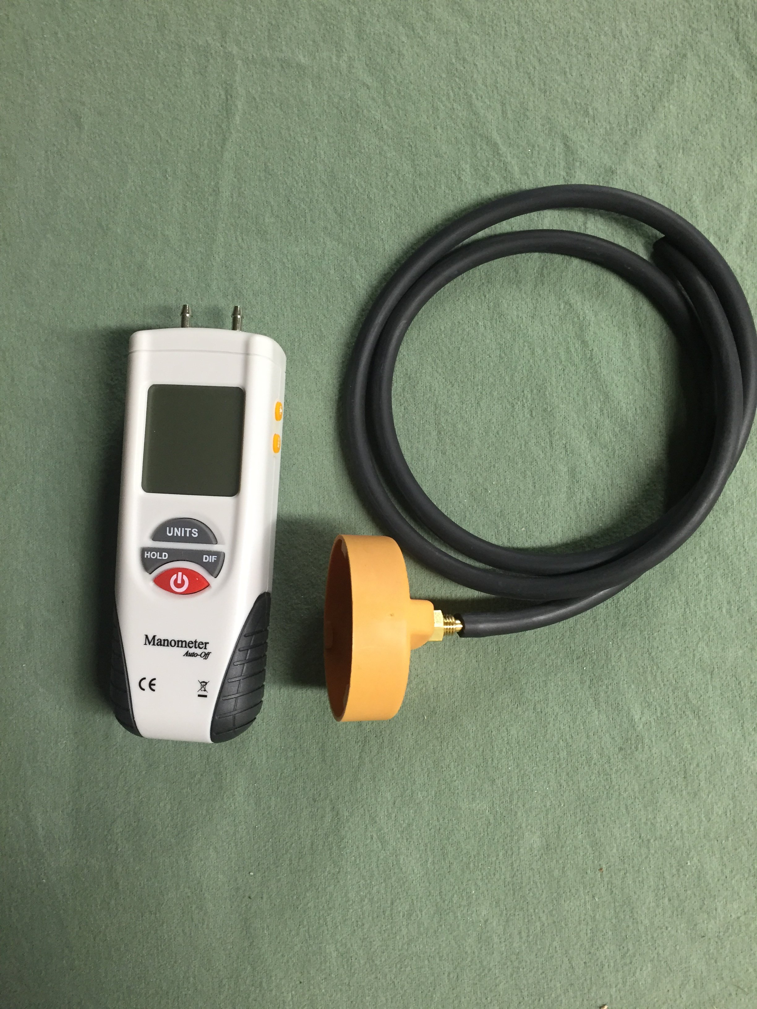
If the oil cap is hard to remove, you have a high vacuum level in the sump, which is bad for a variety of reasons, including lean stalling. The correct way to access the AOS is to fully warm up the engine by driving the car for 10-15 min, then replace the oil cap with the one in the picture above with a hose that connects to the digital manometer. If the vacuum level exceeds 6-7 inches of water vacuum, the AOS is leaking air into the intake system, causing the lean stall conditions. The normal level of vacuum is typically 4-5 inches of water, which is a really weak vacuum level, so it doesn't take much of a leak to cause problems, which is why we always checked every car that passed thru the shop with the manometer.3 points
-
The AOS can either be pin pointed or eliminated by having the car's sump vacuum level checked with a digital manometer (most quality shops have them as the AOS is a perpetual issue; surprise the dealer didn't do this).
 2 points
 -
Welcome to RennTech If you do not have access to a wiring diagram for the vehicle, probably the easiest way to check the ground is to pull the bulb in the light and use a multimeter to check the condition of the ground at the bulb socket.2 points
-
We have used them here in the US for years at MUCH colder temperature's than you get without ANY issues. Put on the adaptor, add external magnets such as the Filter Mag, and enjoy both better filtration and peace of mind.......2 points
-
Welcome to RennTech The factory radio had a ground wire that had to be attached to the car's chassis under the dash as a simple anti theft device. If that ground is not there, the immobilizer will prevent the car from starting.2 points
-
I recently replaced the coolant pipes in my car. I needed to do the job myself because there was simply no way I was going to shell out anywhere from $1500 to $3500 in labor to have it done by the dealership or an independent shop. Plus, having read about the job, I knew they would be tearing through a ton of stuff and I really feared the "oh, it also needs this" scam. I did a LOT of research on the various forums before undertaking this job. Reading and printing out anything I thought was useful information. I would highly encourage anyone reading this to do the same. Fortunately, I was not in the position that the pipes simply failed and dumped all of the coolant. I just had a semi-slow leak… dropping about a gallon of coolant every two to three weeks. So, I had time to order the parts and prepare. Prior to doing this the most complicated thing I had done myself was change the oil, replacing the brake pads and swapping out some plastic bits in the car. I had absolutely no prior mechanic experience whatsoever. However, I do work in IT, and am by nature a very technical person (I'm sure every mechanic reading this just rolled their eyes). My job is troubleshooting very complex problems on very large networks, and I think that experience probably lent itself to a successful outcome here. I'm also patient, and that is critical to getting this job done. I will say that I now have a much greater appreciation for mechanics and their skill set. This was hard. I want to caution anyone reading this that this is a BIG job and it will take a long time. My goal in writing this is so that my fellow Cayenne owners can be spared a lot of the mistakes I made and be better prepared than I was. I will say I am relieved to have this done. I feel a ton better about my car now that I don't need to worry as much about some catastrophic failure hitting me unexpectedly. One rule that I really appreciated was to only place metal on metal when working (until you actually get to removing the pipes). This prevents you from breaking plastic or tearing rubber with something metal. Trust me, pay attention to that rule. I am breaking this down into tasks, because I think it's easier to follow that way. This is how I did it. I am sure there are other ways that may even be easier, but this worked for me and my schedule. I ended up working 4-6 hours at a stretch in the garage with breaks every couple of hours. Step 1: Contribute to this forum I have absolutely no affiliation with this forum whatsoever other than I am a contributing member. The advice on this forum has personally saved me thousands of dollars, and being in IT I know the time and money it takes to run a site like this. So, contribute to the cause. However, there is a second reason to contribute, and that's to get the Porsche TSBs. The TSB for this job contains some diagrams that give you a better idea how all the replacement parts go in to place, and I thought that was handy to have. As an aside, I searched some other issues in the TSBs and found answers to some things the dealership didn't even know… such as there being a $33 replacement latch for my armrest. They wanted to sell me a whole new armrest for $750. Step 2: Obtain the Parts I looked around on the Internet and called some local sources and found a dealership that provided the parts for $550, and that included two gallons of coolant shipped to my door. To me, that was a fair price, and when I received the parts I really thought it was a fair price... there's a lot of quality stuff in there. I'm sure there may be cheaper 3rd party sources. I would just be sure they include all gaskets and such that don't necessarily need to be replaced, but should be replaced if you're tearing everything apart. Once you get the parts, pull them out of the box and examine them. Look at the pics in the forum and look at the TSBs. Get a feel for what you are replacing. Step 3: Verify you have the tools I found the following tools very handy to have, and frankly, necessary. I suggest going to your local auto parts store for most of them and get mechanic grade tools. Socket Wrench 3" Socket Extension 6" Socket Extension Metric Socket Set Torx Socket Set (think of this as a "male" Torx Socket set, you will need #27 & #40) E-Torx Socket Set (think of this a "female" Torx Socket set) Screwdriver that accepts interchangeable bits (there are times this is easier than a socket wrench) Torx Bit Set (Specifically you need a #27 and #40, I just bought a set) Locking Long Nose Pliers (6" is fine, no need for anything bigger) Regular set of pliers Wrench Set (somewhat optional) Real flat head screwdrivers Very long flat head screwdriver (this came in handy a lot) Needle Nose Pliers Small Chisel Set Hammer Tin snips Safety Glasses Mechanics Gloves One of those extension things with a magnet on the end One of those extension things with a mirror on the end WD-40 Some all-purpose grease, like White Lightning Baggies to store the screws in Masking tape/Painters Tape to cover up any exposed openings Old Bath Towels (used to protect the car) Good flashlight Lint free rags Shop Vac Two gallons of distilled water Drain pan (needs to hold 4 gallons) Shop lights A small block of wood, about 2" x 4" x ¾" A radio playing energetic music of your choice Advil and Tylenol Hope and a prayer (optional but doesn't hurt) Step 4: Book the Time I know some people say you can have this job done in less than 8 hours, but being a beginner this took me much longer. If I took out all the time running back and forth to the store for tools and such, and had a guide like the one I am writing, I still think it would have taken 10-12 hours. I ended up removing all of the engine covers on one weekend night, and then doing the actual job the following weekend. I then drove the car for a week with the new pipes and finally put all the engine covers back on over the weekend (I cleaned the covers and the engine thoroughly with a damp rag at the same time to pretty it up a bit). You don't really need to do it that way, but that split the work up a bit. I work in an office in front of a PC all day; I'm not used to working in a hot garage for 8-10 hours at a time... I'm a skinny computer geek : ) When I did the work, I draped some old bath towels over the sides and front of the car to protect it. The last thing I wanted to do was mess up the paint on a zipper or with a dropped tool/screw. Step 5: Remove the Engine Covers There are really two parts to this. You have the decorative covers over the actual engine, and then you have the covers that border the engine. You'll want to remove all of the covers around the border first. There are five of them in total. They all have these little black plastic plugs that you just turn 90 degrees. They should just pop up at that point, but you might have to give them a little lift with a screw driver. While you're removing those covers you might want to pay attention to how they go together and where they slide in to place. You'll also want to remove the windshield washing fluid cap (use the masking tape to cover up the exposed hole) before you remove the cover that surrounds it. Those little things are $4.25 each from the dealership, so try not to lose them. Now you have the three silver looking decorative covers; one on each side of the engine and one towards the front middle with the engine type on it. First, you need to unbolt the two secondary air injection units. Those are the round things with the plastic covers near the back of the engine compartment. You do not need to disconnect them from anything, just unbolt them (three screws each) and then move them off to the side. It might be a good idea to get some labeled baggies to store the screws in. Once those are removed you can get to the side engine covers a little easier. The engine cover in the front middle you just lift off, just work it back and forth a little and it should pop off. Take note that there are four little plugs that fit into holes on the cover itself, you'll need to find them again when replacing it. Now remove the one on the driver's side. It's pretty easy to remove. There are four screws towards the bottom that need to be removed, and then the cover will just come off. The one on the passenger side is a bit different. You have the engine mount right in the middle of things. Assuming you have the tools, you can unscrew the engine mount and get it out of the way. That will let you get to each of the four screws easily on the cover and remove it. I wasn't so lucky here (didn't have the right tools at the time), so I just got the four screws out of the cover and ended up wedging it out. While doing that, the piece of the cover under the engine mount snapped off. I wasn't too concerned about this, because where it snapped is hidden by the engine mount. When I put everything back together I just slid it back and screwed it in. You can't tell at all that it was ever snapped in half. Step 5a: Remove Fuel Pump Fuses You'll want to check your manual (you can also download the manual from this site), but you need to remove a couple of fuses for the fuel pump. Right in front of the driver under the hood there is a small compartment. Remove the cover, and then remove a second cover to expose the fuses. Mine were fuse 14 & 15 for the fuel pump. Store them somewhere safe. Once those are removed, start your car. It will run for a few seconds and die. Congrats, you just removed most of the fuel from the fuel line. I know some people don't disconnect the fuel rail or anything, but to me that's a bad idea. I had a lot of time to try it that way and honestly I'm glad I got it out of the way. Step 6: Disconnect the fuel line The fuel line is near the back center, it's just one tube running to the fuel rail. You'll disconnect it by using a wrench and a pair of pliers. You're unscrewing the part on the left (the thin part) from the part on the right (the wide part) which shouldn't turn as it is part of that tube. Once unscrewed, the fuel rail is only connected to the manifold. A little residual fuel might leak out, so you might want to have a rag handy to wipe it up with. Use masking tape to cover up any exposed holes. It wouldn't be a bad idea to disconnect the batteries now either. I didn't, but that was probably stupid. Step 7: Remove the Y-Pipe that goes to the Throttle Body This plastic Y-Pipe is right up front so it's very easy to get to. There are two flexible pipes on either side you need to remove first; just use a screwdriver to loosen the two clamps on each of them and you should be able to compress them enough to remove them. The Y-Pipe itself is attached to the throttle body via two long, plastic bolts. They have a screw head on them but they are not screws, they're more of a key. You just turn them a bit to line the key at the bottom (use a flashlight and you'll see it move as you turn it with the screwdriver) with the slot. When it's lined up, use a pair of needle nose pillars to lift it straight out. It's plastic and may be brittle, so be a little careful. You will need to remove an electric connection to the throttle body in order to get to one of them. There is a tube connected to the bottom of this y-pipe, so you can't just lift it out. It has some give to it, but not a lot… just enough to get your hand under there once you pull the y-pipe off the throttle body. You have to press the buttons on each side of the tube in order to get it off the y-pipe. Step 8: Remove Emission Tubes & Electrical Connections from Throttle Body There are two emission tubes crossing the throttle body, Porsche refers to them as "vent tubes." I know this because one snapped in half when I removed it, and the dang thing was $130 to replace. To remove them, you just need to press the clips at either side of the end of the tube together and then pull it straight out. I don't think mine had ever been removed, and in retrospect a bit of WD-40 used sparingly here might have been a good idea. I think I used too much force and that's why the small one snapped. I have read that some people have replaced this broken tube with a more generic tube from a hardware store. I just spent the $130 and did it right. There is a third tube connected to the throttle body, you just need to remove that one end of it. You will also have two electrical connections to remove. One you had to remove to get the y-pipe off in the previous step. Just remove the second one and then you're done. Step 9: Remove the Throttle Body The throttle body is connected to the manifold via four bolts. Remove those four bolts and it will come off. You sort of have to wiggle it out because of that thin metal bracket that's holding it there, but it will come out easy enough. Some people take this opportunity to clean it. You'll probably see some gunk on the back side of it on the inside. Step 9: Remove the Electrical Connections to the Fuel Injectors There are eight fuel injectors connected between the fuel rail and intake manifold. Mine were blue plastic, and there is an electrical connection running to each of them. There is a metal clip at the bottom that you just need to press up. I placed a flat head screwdriver between this clip and my index finger, and pushed up and pulled at the same time to disconnect it. Once you remove one you'll get the trick and the rest will come right off. Step 10: Remove the Intake Manifold with Fuel Rail Attached I know a lot of people have different ideas here, some people want to remove the fuel rail independently, and that was the first way I tried it. In retrospect, it's much easier to just leave it attached. There are four screws that hold the fuel rail to the intake manifold. I would recommend leaving these alone, especially since the one at the back on the passenger side is nearly impossible to get to. These screws are $6+ each… I know because I lost one. :P There are 10 bolts that need to be undone to remove the manifold. They don't come all the way out, they'll stay attached to the manifold. Once you loosen them enough they sort of come free and wiggle around. The one at the back on the passenger side was a bear to get to. I ended up placing the Torx Socket bit on top of it using the magnetic extension thing. I then put the 3" extension on top of it, and finally attached my socket wrench to it. I kind of built it all up I guess. I then went really, really slowly and loosened it up. Once loose, make sure to vacuum up any debris on the engine. When you pull the intake manifold off you will have eight gaping holes right down to your cylinders, you don't want anything falling in there. You can now scoot it forward a bit to get to the tubes you will need to disconnect. There are two tubes at the back of the manifold… a firm one and a flexible one. The firm one is just like the one under the y-pipe, and is easy enough to remove IF you can get enough pressure on the connector. The flexible one was just kind of stuck on mine and I left it on. You kind of have to scoot the manifold forward and angle it out, but it will come out with the fuel rail attached. You may have to remove some tubes and such from their guides or brackets. That flexible tube was long enough that I just put the whole thing on the driver's side of my engine and left it there. It didn't seem to be sitting on anything that couldn't support it. I'm sure it can be removed, but at this point in the job I was tired, hot, and just wanted to keep going. Once off, IMMEDIATELY cover up the exposed intake holes with long strips of tape. Cover them completely, and make sure they STAY COVERED. Shine a flashlight in each hole first to make sure nothing fell down there. If so, get it out as delicately as possible. Vacuum up any other debris you see. You can now see the infamous coolant pipes. Step 11: Assessment At this point, you can see the coolant pipes and should be ready for the meat of this repair. The starter is right there too… right under the leaking pipes. Brilliant, isn't it? This may not be true for you, but I had an AMAZING amount of debris in here… honestly looked like a bird had built a nest. I have no idea how it all got in there, but some where at some point tons of debris got in here, and now it was all soaked in coolant. I think my coolant leaking may have been mitigated because the wet debris probably acted as a mud and sealed everything up a bit. I vacuumed it up with a shop vac prepped for a wet cleanup. Now you need to decide if you will see this repair through or not. Once the next step is taken, there is no going back, and honestly the toughest part of this job by far is getting the old pipes out. Step 12: Drain the Remaining Coolant Your first goal is removing as much coolant from the car as you can. On the V8's, there is a drain plug at the bottom of the car, but on the turbo's you won't have one. That drain plug required an allen bit that was larger than I had on hand or could even find at a hardware store. Honestly, in retrospect I wouldn't have even bothered locating it. I'm sure there's a pipe down there you could remove, but I didn't waste time looking for. I took a tip I found on a forum, and drilled a hole right in the middle of the center coolant pipe (of three) and used a siphon with a hand pump to drain out every bit I could. I repeated this process on the larger lower pipe. DO NOT SIPHON BY USING YOUR MOUTH. Coolant is dangerous, nasty stuff. Make sure there are no animals or kids around while you are doing this. WEAR SAFETY GLASSES AT ALL TIMES! Doing it this way you're going to spill a lot of coolant, but it is what it is… they've been leaking all over everything anyway. I used my shop vac to vacuum up anything I could that escaped the siphon. I've also read of people renting professional vacuum pumps to suck it all out, but again, that's more complicated than it needs to be. I did some research, and coolant is not currently controlled by the EPA for disposal, and it can't be recycled. The unofficial advice I got was to dump it in the woods and douse the area with a hose for a bit. Do not dump it down the drain or dump it where animals could readily drink it. Don't dump it in a stream. Presumably it breaks down fast enough on the ground that there isn't a long lasting effect. Step 13: Remove the Three Upper Coolant Pipes The first pipe you need to remove is the long skinny pipe with three connectors. This one is easy enough to remove, and you should have a replacement as part of the kit. One of the connectors broke off in the hole, and I had to very carefully remove the pieces. Relatively speaking this was easy compared to the rest. There is a compression ring that needs to be removed for the connection at the back of the engine, use the locking pliers to do that. Cover up the exposed holes with masking tape. You now have to remove the three upper coolant pipes. There is a bracket at the back of the engine holding the three pipes. There are also two clips attached (you'll be looking at the back side of them) to that bracket that just support a hose at the back (just has electrical connections in it, and it's probably already split so you don't have to be super careful). Pinch the connectors with a pair of needle nose pliers and they'll come off. You now have to remove three bolts from it to remove the upper half of that bracket. I removed two of them but couldn't get to the third without snapping the thing in half. Porsche was kind enough to provide a new one in the kit so I wasn't worried about it. You will now see three rubber hoses attached to the plastic pipes. They are held on to them with compression rings. Use the locking pliers on the rings to loosen them (they need to be squeezed together to loosen) and slip them back over the pipes. I did one at a time, completely removing the ring and setting it off to the side for safety. The locking pliers really excelled here. When using them, attempt to come at the ring from the top instead of the side, the grooves on the pliers will then secure the ring quite nicely. You might have to adjust the pliers a couple of time to get the right amount of the compression for the ring to move freely. With those ends free, I used the shop vac to suck out a lot more coolant. Once done, cover up the exposed holes with masking tape. Once those three ends are free, you'll need to free up the other ends. Here's the deal, they are probably going to break when you try to remove them, and probably going to snap off at the spot where they connect to the coolant reservoir. I twisted and pulled and sure enough, they snapped off. You can remove the lid of the coolant reservoir by removing several screws, a small aluminum pipe on top, and the rubber pipes towards the front of the car. The small aluminum pipe has a single screw that needs to be removed. There is probably a lot of corrosion here so you may need to use a flat head screwdriver to pry it out. Be careful, it's flexible enough to come out and get out of the way but just barely. There is a compression ring on each of the rubber pipes that is easy enough to get to, just loosen and slide it down the pipe. Suck out any coolant and cover the exposed pipes with masking tape. Once you have that lid out, you'll see the remaining plastic bits in the holes. It's difficult to move, but those plastic bits are just in there with pressure, they aren't glued or anything. I used a small chisel and the hammer to break them out. As I got to the o-rings I pulled on those with needle nose pliers and in one instance the whole chunk came out. I also used a lot of WD-40 to work everything out. What you don't want to do is take any risk of chiseling into the metal of the lid, so be careful. This is all about removing the plastic material. Each bit you remove gets you one step closer to freeing up enough pressure to get the remaining bit out. Once it's all clean, leave it off to the side while removing the big pipe. Step 14: Removing The Big Pipe This one is tough. Make sure you're rested, well fed, and cooled down a bit. If you're aggravated already, walk away and relax a bit. You will need to break this pipe into two pieces. I used a boring bit to drill a big hole in the top, and then used tin snips to cut chunks out until I got it in two parts. Again, I used a shop vac to suck out any remaining coolant as I went along. Really, anything will work… you could even use a chisel to break it out. It's coming out one way or the other, no need to be pretty about it. Once it's in two pieces, you can probably rotate the two halves apart. Use WD-40 generously on the ends first though, and give it a bit to work in there. Regardless, when I went to pull out the two ends, they ended up snapping off… leaving their end pieces in the hole. If you read through the three forums, different people use different techniques to try and avoid this with mixed results. This is the worst case scenario though, so lucky for you I fought through it and have plenty of advice. Assuming your pipe broke off as mine did, you will see a metal ring in each end, with black plastic between it and your car. That metal ring was an inner support ring for the original pipe and needs to be removed. This is a violent procedure. IMPORTANT: I cut up some lint free cloths and stuffed one into each end as far as I could so that any material from the following procedure wouldn't go any further. Once done with the procedure below, I vacuumed up anything I could and then removed those cloths. Again, use WD40 a LOT. I sprayed and sprayed as a worked, and I think it helped. READ THIS CAREFULLY: Removing the plastic and metal ring from each end is all about removing material. You are trying to get as much plastic out as possible. If you get the ring out first, great, but it's not 100% necessary. The plastic is what needs to come out, and you need to get it out from all around it. In addition to the plastic, there are two o-rings in there, so they are just adding more friction preventing this from moving. You'll get bits of that out as you work, and that's good. Eventually, you get enough bits out that the rest will just fall out. Use a hammer and chisel to collapse the metal ring on the top and sides as much as possible. I used to the chisel to cut in to it a bit too. Once I got it that far, I switched to the long screwdriver, hammering the end of it into the plastic over, and over, and over again. I pried as much as I could and worked out bits of material. This took a long time, but sometimes you'll get a big chunk out and that will give you renewed hope. Again, this is all about material removal. Keep telling yourself that. Every bit you get out makes this easier. Once you get enough plastic out, you'll see the metal ring move a bit as you work. This is a great sign and you are almost done. Ultimately, you should be able to pry it out with the screwdriver. NOTE: When working you want to work as much towards the metal ring as possible. You want to avoid scraping the inside of the hole where your new pipes will go. I did scrape up mine a bit, it's unavoidable, but regardless my new pipes don't leak. When you go to remove the bits closest to you, you're working somewhat blind and it is hard. This part almost broke me, but I used a mirror to check and recheck my work as I went along. Bright lights help here too. Honestly, I really can't say enough how hard this part was and how long it took in comparison to everything else. It was the part that had me the most worried, but I got through it. Once it's all out, remove the cloths from inside the pipe and vacuum a lot. Now is the time to clean stuff up too, as you're about to put the new pipes in. As a best practice, you should clean up the inside of those holes. I used some steel wool; I know some people used scotch bright or even buffing pads. I didn't go overboard with this; I just want to get any grime out of there. Step 15: Install the New Big Pipe At this point you should be elated. You're through the worst. Installing these pipes are a bit difficult, but not bad. If they are not already on there, put the O-Rings on the small pipe. Use the White Lightning grease or whatever you bought and coat the inside of the hole on the engine and the outside of the pipe. Use it liberally. A bit of WD40 wouldn't hurt either. Press it into the hole at the back of the engine and do your best to get it all the way in. This is where a small block of wood and a hammer come in handy; you can use those to tap it in the rest of the way. Do not put the rubber sleeve on it. For the big pipe, install the o-rings and lube everything up good with the grease, both the hole it goes in and the pipe itself. You will also need to grease up the end the rubber part goes on and the other end of the short pipe that the rubber sleeve will slip over. Place the tightening rings over the rubber sleeve as well. Slide the rubber sleeve as far as it will go over the pipe. Push the pipe into the hole, I found a twisting action worked well. I also used my metal screwdriver against the bottom of the engine bay as a lever to slide it in the rest of the way (it required a lot of pressure). You then need to rotate it to line it up with the short end of the pipe. You'll slide the rubber sleeve over it and then tighten up the two rings. NOTE: Be sure to rotate the rings as far down as possible so that the screw does not interfere with the three pipes you're about to place on top of it. The new big pipe should be in place, and you're now done with the hardest part of this job. Step 16: Install the Three Pipes You'll want to put the lid back on the coolant reservoir (replacing the seals Porsche included with the kit), reattach the pipes and tighten up the screws. DO NOT OVERTIGHTEN THE SCREWS. I snapped one clean off. Make sure they're tight, but don't put all your muscle into it. Once on, you are ready to slide those pipes in. You do not need to put the lower bracket at the back on first; I did it after installing the pipes. Again, make sure everything is lubed up well so that any points of friction are well covered. Slide the pipes in. I used by long screwdriver again as a lever to apply the necessary pressure. On both these pipes and the big pipe it looked like I could have gone another 16th of an inch, but nothing leaks so I guess it was far enough. Put the bracket on at the back before you attach the hoses. You'll use your locking pliers again to attach the compression rings. With the bracket in place it is obvious how far up the hoses go. You'll put the upper bracket on, using the spacers for the screws and screwing it down tight. Don't forget to attach the two brackets that hold that electrical cable in place. Not a big deal if you do forget. Step 17: Install Final Pipe Now install that skinny pipe. This one is easy. Don't forget about the small compression ring that goes at the far end. Everything else just clips in. Step 18: Assess Your Work Look over everything and make sure it all looks right. At this point you should have a sealed coolant system. Check all your connections and make sure everything is solid. At this point you're home free, and you should be feeling pretty darn good. Step 19: Fill Up Coolant I use a 50/50 water to coolant ratio… so I mixed everything up with what I had and filled up the coolant tank. Once it was full, I left it overnight and checked in the morning for any fresh coolant. I was totally beat from a long day of working on it and thought putting everything back together fresh in the morning was a good idea. Step 20: Put Everything Back Together You tore it apart, now put it back together. I cleaned everything as I went, so now my engine looks great and I think that's a good idea. You don't need to go overboard, just use some lightly damp, lint free rags and wipe everything down. Porsche should have also provided new seals that go on the bottom of the intake manifold. I replaced mine dutifully, and I am glad I did. The old ones just looked worn out, no way they weren't leaking. Putting everything together is pretty straightforward once you've taken it apart. Just be careful and make sure you get all electrical connections and hoses in back on securely and in the right places (hard to mess that up). Also make sure you remove every bit of masking tape as you go. Final Thoughts I am very, very glad I did this project for two reasons. One, it saved me a ton of money and two, I now know tons more about the engine. Doing this project means I could replace my fuel injectors, spark plugs, injection coils and a host of other things when and if I have to. I know where the throttle body is, and if it's sticking I know where to go to clean it. If I need to replace the starter, I know where it is and how to get to it. I can now take my car on trips without fear of a massive coolant leak. This was the last "major" Cayenne defect for me that needed to be fixed. The water pump & drive shaft were already replaced. With 116,000 miles, I have quite a bit of faith in my car not having a catastrophic failure (knock on wood). At the end of the day, I'm pretty proud of myself for getting this all accomplished, and I hope I've saved some other poor soul a ton of time by writing all of this down. If it does help you out, please reply to this post and let me know.2 points
-
Be sure to use some protective material on the mirror base. Set the pliers with the protecting parts to the windshield to the diameter of the mirror base and secure to the mirror base. Turn the rearview mirror through 90 degrees at the mirror base using the pliers. Then, unclip the base of the interior rearview mirror from the retainer plate on the windshield. When you reinstall the mirror be careful not to go beyond the 90 degrees locking point. If you remove the mirror base from the windshield you will need a special cleaning/glue kit from Porsche to reinstall it.2 points
-
Try 76821 point
-
Remember the new ride height will be 10 mm lower than the stock height - plus the springs, struts and swaybars will all be firmer than the stock items. As I said before another option PSS-9 (adjustable) Coilovers - likely easier to find as either OEM or aftermarket.1 point
-
Having spent months chasing down my very heavy steering (yes I know some like it like that) I have finally managed to over come the heavy steering by bypassing the servotronic system and locking it into 75% assistance effort. Here's how I did it, but I would appreciate any thoughts on why it wasn't working if anyone has any constructive comment about the acceleration sensor readings - which is what I think the main culprit is.1 point
-
Chances are your 20 plus year springs have softened and are already sagging a bit. Springs, swaybars and struts are a matched set - I would not mix them as you could produce unstable handling. Especially if you track the car. RoW 030 is fine for street and most track driving - you just have to be careful of large speed bumps on the street. PSS-9 (adjustable) Coilovers can supply suspension tuning and even lower for track days - but you would definitely want to raise it up for street.1 point
-
Sometimes these systems store a lot of secondary codes that confuse what is really going on. I would start by clearing all the codes and then see what comes back.1 point
-
Non, push down with one hand, squeeze the ribbed bottom ring with the other hand and pull up, this is not as easy as it looks, succes.1 point
-
I'd start with checking the alternator, is it putting out 14.5 V DC at idle? If not, I would check to make sure you properly reconnected the wiring.1 point
-
What are your voltages? Resting, idling, driving above 2000rpm? There are gizmos to help with this monitoring - Antigravity Batteries has a battery tracker. Others plug into the cigarette lighter. Do you have any codes (can be read with Durametric and other (OBDII) readers)? I've read stories on Rennlist about induced electrical noise in the sound system even when the sound system is not turned on. Might your alternator be damaged or no longer have a high quality ground? Could the noise be mechanical (transmitted noise)? You did change pulleys. Run the car a few minutes without the serpentine belt and see if the noise is reproduced.1 point
-
Do this someplace safe... Put in Neutral and see if the noise continues or not. If it does not continue then it is likely in the drivetrain (transmission, transfer case, driveshaft, rear end}. If it does continue then it is likely in the running gear (wheel bearing, axle shaft, or even warped brake discs).1 point
-
Try 07581 point
-
Try 53461 point
-
Try 54251 point
-
I do not, we normally stock a variety of wire sizes and colors, heat shrink tubing, connectors, zip ties, and the like that we source from a local electrical vendor, but you can find similar supplies from multiple sources like WireCare.com | Your Local Cable Management Superstore! WWW.WIRECARE.COM WireCare is your online wire & cable management superstore. We have what you need for connecting, harnessing, & beautifying all of your electrical projects. We carry the highest quality... .1 point
-
Try 67041 point
-
I've been receiving this code and trying to run it down. The car runs as expected, and the only issue is that it is difficult to fill (pump shuts off almost immediately unless I fill it very, very slowly). It seems likely the two are related, but that's unconfirmed. In researching the code, it seems most have the "Pressure Sensor / Short to B+" code variant, not "Pressure Sensor / Switch High". The one post (6speedonline) that had a similar code was resolved by discovering a mouse ate the wires. That's possible, but I cannot see any evidence of this, and the circuit seems to be in tact (though if you have a testing suggestion, I'm all ears). With the code combined with the fuel fill issue, my working assumption is that it is the tank vent valve stuck closed. When researching that issue, I see that pretty much all results I found were folks encountering a valve that is stuck open - they get a whistle and maybe a CEL code for low pressure. Any advice, tips, or diagnosis methods?1 point
-
Try 34121 point
-
Try 48701 point
-
I haven't seen on these forums anyone who has rebuilt their 997.1 using LN Engineering nickies. I just thought I'd share my experiences. I had a stock 997.1 2006 Carrera S. At 132,000 i scored a cylinder in the middle of nowhere in Kansas. the rebuild consisted of: 1. LN Engineering 4.0 “nickies”, ceramic hybrid ball-bearing IMS retrofit, and JE Pistons2. LN Engineering low temperature thermostat3. 997.1 "Competition" Carrera IPD Plenum & GT3 throttle body 4. third radiator 5. replaced water pump the ever so quick summary: low end power--amazing. mid range--amazing. high range rpms--amazing. for those of use that like the “feel” of a 996 and 997.1 (the 997.2 and the 991 are, to my mind, fundamentally different in this regard), this rebuild results in an intoxicating drive. I haven’t put this thing on a dyno and to be honest i’m not all that interested. the horsepower gains are so prominent, it would simply be an academic exercise to establish that I have from +60hp to +75hp--it’s that impressive.Things to keep in mind This turned out to be a very long process. if you are deciding on doing this, please check with LN Engineering to understand what tools are required. I had my car rebuilt twice by a nationally renowned porsche mechanic (he has won several awards on his expertise in building porsche race engines) at a porsche dealer. the first time didn’t go well as there was a chip in one of the pistons that required them to do it again. what went wrong? i don't really know. on the one hand, upon looking at the old water pump after the second rebuild, all the "fins" were chipped away and indeed the pieces may have found a way to the piston. on the other hand, there appears to have been special tools that even they didn’t have to properly install the pistons the first time around (this is my interpretation of what representatives at JE Pistons and LN Engineering told me). they purchased the necessary equipment the second time around and the result is amazing. Ladies and Gentleman, there aren't many porsche shops in the United States that have opened up a 997.1 engine and put it together again successfully. This particular shop had three mechanics who regularly open up 997.1 engines. The mechanics at Aristocrat Motors in Kansas City are excellent at what they do and sill we had to do it twice to get it right. we learn from making sense of the unknown and I have no doubt that Aristocrat Motors would do an excellent job on your car if you decided to go this route. I’m only mentioning this to emphasize that no matter how good that mechanic is, check with LN Engineering to make sure that the place where you are having this done has the proper equipment. if not, there is a more than probable chance that mistakes can happen during the tuning.1 point
-
Found the solution, the circuit board inside to control unit was corroded at the power input, cleaned resoldered and now working! That’s saved a fair few pounds, just all the trim to put back1 point
-
Time to run a parasitic drain test, which has been written up multiple times, but there are also a ton of online videos : . Basically, after the car has been sitting for about an hour or so, there should be a 45 - 60 milliamp current drain on the battery from necessary things like the clock and the alarm system; any higher than that and you have a parasitic drain on one or more of the electrical circuits.1 point
-
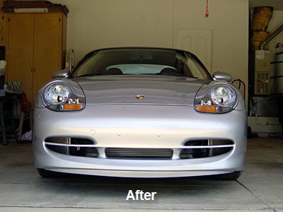
Cayenne GTS/Turbo front bumper upgrade So, After a productive Easter break I have upgraded the front of the Cayenne `S' to look like the GTS/Turbo model. Always thought the bigger front grille made the car look more `planted'. The attached deck shows the steps I went through if anyone else fancies trying the change but would alse be helpful for any mod that requires the front bumper to be removed. I also installed the front steel skidplate while upgrading the bumper and will post this as a separate guide shortly. Any questions or Author jamesevelynclarke Category Cayenne (9PA, 9PA1) - Mods Submitted 04/25/2009 01:31 AM Updated 09/30/2016 01:42 PM1 point
-
Hi..I live in rainy Ireland and this has been a real problem in my 996 Cab. I brought your water drain diagramme to my garage and they removed the interior side panel to find an easy solution. A number of drain tubes collate into a collection point like a mini funnel which had built up a pot of sludge and water could no longer flow through same and out of the car...so diverted to the back foot wells. Who thinks up the stupid systems??1 point
-
Recently ran into this issue as my mirror fell off. (Thankfully it didn't break.) For those to whom this happens, the method above will not quite work. If your mirror falls off (with the base attached), clean the residual glue off and identify the metal circular base, which extends about a .25 to .125 from the base. For tools, I used a crescent (vice) wrench like the one above pictured. I also used channel locks, a microfiber towel, and (importantly) gloves. Last thing you want is the tool to shear off and bang your hand up. Attach the crescent wrench to the metal base. Wrap the microfiber towel around the mirror base housing and get the channel locks affixed. Twist the metal base COUNTERCLOCKWISE 90*. This will unlock the metal base from the mirror base housing. Acquire some glue (I used the 3M high bond adhesive), clean the working surfaces and reattach. Done.1 point
-
The MY05 Carrera Owners Manual is now online and available for download. You can download it here (special thank you to Viken) (corrected link)1 point
-
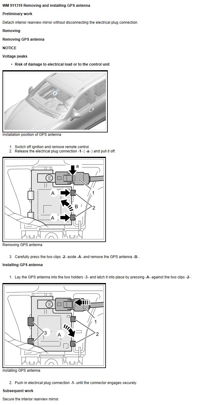
Osunick, Your GPS antenna is located behind the rearview mirror. Hope this helps.
1 point
-
Those struggling with that lower nut- there is a rubber plug which when pulled provides access to the nut.1 point
-
1 point
-
I will be posting a starter repair/cleaning tutorial for the Porsche Cayenne. I bought a 2006 S a few months back and it had the startup whine that I believe is common to this vehicle. I have replaced the old starter with a Chinese $130 job, but I don't trust that the starter will last. I was amazed that no one had posted a DIY for this since the new Bosch starter is so **** expensive. As of right now I have most of the starter disassembled (which was not difficult except for one part that I can't figure out). As I clean and put back together I will post pics and advice. I found a few sites where you can get starter parts, mostly in Great Britain. I used a parts company called saverepair.com. Unfortunately, Bosch doesn't supply a lot of parts specific to this starter. The starter number is 0 001 125 025. Other good reference sites are aspwholesale.com, https://en.as-pl.com and this parts breakdown helped TREMENDOUSLY http://www.woodauto.com/Unit.aspx?Man=BOSCH&Ref=0001125025 (which wood auto was my second choice for parts but they cost a bit more.) What I could order from saverepair.com were these parts. bsx208-209 Bosch Starter Motor brushes 5.8 mm x 18mm x 14.6mm. 1 €3.60 €3.60 wsbu9016 Starter Bushing 10,08mm x 14,04mm x 9,90mm Rear bushing for Bosch,Front Bushing for Valeo D7E, and Centre for Ford Motorcraft. 1 €0.55 €0.55 wsbu9022 Starter Bushing 28,47mm x 32,30mm x 10,00mm. Front bushing used in Self-Supported Bosch starters. 1 €1.72 €1.72 wss0020 Starter Solenoid for Saab 9-3 Turbo 9-5 Turbo 900 9000 Opel Astra F Corsa A B Kadett E Vectra A B Lancia Fiat and more. 1 €18.00 €18.00 Pretty cheap parts as you can see. When I received the parts I was a bit concerned that the solenoid wouldn't work (I basically picked it by cross referencing starters that were close to the number range and had the same type of connectors). This solenoid is a bit larger than the old one, but the screw holes match up perfectly. I have never replaced bushings or brushes before, so this will also be an adventure I'm sure. On a side note, I REALLY wanted to replace the main bearings on the starter, but there are a few things I can't figure out. There is a part called the bendix that has the gear at the end that also holds the bearings. It is also attached to the stationary gear and a spiral gear shaft. I can't figure out how it all separates. If I did, I could just replace the entire bendix with the bearings on it. I'll see if I can attach a pick of what I'm talking about. If I can't get them separated I think it will be fine as the bearings still turn. I believe the major points of wear on the starter is the bushings. There is wiggle and play on the shafts on the bushings, which is probably why the starter was whining. Stay tuned! One more thought on removing the starter itself. There are write-ups for that so I won't delve, I will say, it is a relatively easy job of removing parts to get to it, but it does take a lot of time. I was able to remove the starter also without disconnecting coolant lines. I also added a pic of me after ripping the engine apart, with a much rewarded pipe blend called "quiet nights" (completely irrelevant to the post, ha!).1 point
-
Thanks to Gelbster in the 986 forum for pointing me to this post by Dale_K in the Pelican forum. In fact, it was the magnetic switch which was not inserted into the space provided for it in the valve. It had fallen out when I pulled the old valve but I didn't notice. I did see it but couldn't find any information on it until I saw this post If this unit isn't working you'll have trouble filling. Also the magnetic switch. A new one comes with a new vent valve.1 point
-
2001 C4 Cab. 58k miles. I have this exact problem, ticking that happens at idle, but slightest depression of clutch pedal makes it stop. Got new clutch 4 months 4 k miles ago. The noise started a few weeks ago,. Any idea how in the world the clutch master could be making that noise? Reluctant to replace without seeing how it could be the problem. Thanks.1 point
-
1 point
-
For the fingertip test: Turning on the A/C to cause the low speed relays to click on and off will only happen when the coolant temperature is below 206 degrees Farenheit. If the coolant temperature is above 206 degrees, but below 215, the low speed fans will turn on (and the low speed relay will click) without pressing the A/C button on. Regards, Maurice.1 point
-
I have a 2005 Carrera S with 68,000 miles. I recently started having problems with a large white cloud appearing only at start-up and some poor throttle response at low rpms. I had also noticed for the last few months that the oil consumption seemed a faster than usual for my car. After a little reading I found that it might be due to the AOS. My Durametric program was giving some RKAT and misfire codes, but the check engine light (CEL) was not on - of course, after I checked the codes, the CEL came on. With the engine running, I tried to remove the oil filler cap but couldn't - I would have had to pry it off the tube. So it really did seem to the AOS. Apparently when the AOS goes bad, it causes a high vacuum in the crankcase (hence can't pull off the oil filler cap) and this pulls oil into the recirculation system that drains into the intakes (hence the white cloud at start-up and high oil consumption). I looked around and found some information on Rennlist discussing AOS replacement on a 996 (http://forums.rennli...labor-time.html). People discuss dropping the transmission or lowering the engine to help with this. I'm my case only removing the engine would have helped. The hose clamps are pointed towards the back of the car so I would not have been able to do this from the transmission side. You should know that the 997 S uses a different AOS than the non-S 997 or the 996. Based on all this information I ordered from Zim's (www.allzim.com) AOS for ~$150 3 intake gaskets (~$8) (didn't use these in the end) one throttle body gasket (~$7) as well as a new serpentine belt, and all three idler pulleys (pullies?) because I thought I would do this at the same time. Tools are shown and with some listed at the bottom. First, the pre-picture . Obviously I have a fabspeed cold air kit. The red color sticks out like a monkey-butt, but I like the sound. The AOS on the 997s is under the passenger side intake manifold about halfway to the front of the engine. So some things have to come off... the air box needs to come out, there is a good air filter replacement tutorial here on Renntech. This picture shows the air box partially out and rotated over so that you can see the connections. I also zoom in here just to show the vacuum connection on the solenoid, one of the electrical connections on the solenoid (already disconnected), and the mass air flow (MAF) sensor connector. Just ignore the broken wire clip. Some gremlin must have done that... Now the throttle body has to come off - there are four E-10 bolts, and the bottle left one has a bracket that hold a little rubber bumper attached to it. Only the four E-10 bolts need to come out. There is also an electrical connector at the top (runs from left to right) and if you squeeze it just right on a tuesday with a full moon, it will pop off. Here are two pictures of the throttle body off the car, note that there is oil on the inside and both the inside and outside need cleaning. Now to get the intake pipe out from between the left and right manifolds. You can see that there is the plastic Y splitter that the throttle body attaches two, and then two short rubber hoses that attch the plastic splitter to the intake manifolds. There is a recirculation hose connected to the top left of the splitter. The other end of this hose is connected to the AOS. Porsche was VERY nice when they made these hoses, if you squeeze the two textured parts together the hoses pull off easily - no wire hose clamps. Yeah Porsche! Also notice that this splitter piece has the groove where a new throttle body gasket should go. Each rubber hose has two large hose clamps on it. In order to get the splitter out, I recommend loosening only the two outer most clamps, that is the clamps on closes to each intake manifold, because then you can rotate the splitter up or down to help break the seal of the rubber hoses on the intakes. Then I removed the inner two clamps and broke the seal of the rubber hoses to the splitter. To get everything off, I pushed the rubber hoses as far onto the intake manifolds as I could (essentially pushing the two rubber hoses father apart) , and then the splitter came out from between the hoses. In retrospect - and after putting all this back together, I would have pushed the rubber hoses closer together onto the splitter and then taken out the splitter with the hoses attached as it went back on this way pretty easy. Here is the splitter And here is where the splitter was... In this last picture you can see the short rubber hose segments, the disconnected recirculation hose, and the back crossover tube that also connects the two intake manifolds. If you follow the disconnected recirculation hose down, you can see the top of the AOS. I could see that a fair amount of oil had collected in the intake system. I also removed the power steering reservoir - there is a 10mm bolt on the right side holding it to the right intake manifold and a plastic tub that connects down to the pump. That tube has a nice twist connector on it, twist it to the left (counterclockwise) about a quarter of a turn and the whole thing will just pull out. This picture shows where it was, and the black plastic tube that has a green o-ring is where that reservoir was connected. Now I removed the 4 E-10 bolts that held down the right intake manifold to the cylinder head. This is where things may have been easier on the non-S or the 996? My intake manifolds are one piece with the injectors attached to the bottom. There are 4 bolts, one on each end and one between each pair of cylinders. If we number them from rear of car to front, number two was the real pain to get out. There is a sensor embedded in the manifold directly above this bolt which made it difficult, but eventually the right combination of extensions and u-joint made it possible (it was harder to replace than to remove). I couldn't really get a good picture here. I couldn't easily figure out how to get the fuel supply line and injectors disconnected, so I couldn't pull out the intake. Removing the intake bolts did left me move it around some which was helpful, but I'm note sure it was actually necessary to get the AOS out. Also, since I couldn't get it off, I couldn't change the gaskets - so I'll keep my fingers crossed that the old gaskets are still in place. This picture shows that I've removed the old AOS - you can see the recirculation hoses that attach to it (there are three - two on the left and one on the back), and then two small coolant hoses (both on the left). What it doesn't show is that there are two small T20 screws that hold the AOS to a bracket on the cylinder head. See the diagram below for better idea. I sure hope your hands are any larger than mine... I used a T-20 bit and a small ratcheting monkey wrench to get to these. If I hadn't loosened the right intake manifold, then I'm not sure that I could have gotten my hand in there to do this. There are the two coolant hoses that have to come off, one of them come from the water pump and there is a small segemnt of it that is rubber with a spring clamp right at the water pump fitting. This picture shows where I'm talking about. In retrospect I don't think I had to take this off, but it was easy. Please ignore the broken oil-pipe filler. Who did that? Turns out that this filler just sticks out into space and it is really easy to put too much pressure on it with your arm when trying to work on the intake. It snaps with a nice crisp pop that reminds you of a broken bone. Turns out it is a $40 dollar part that has to be ordered and it looks like the alternator has to come off to replace it. I think I'll keep my serpentine belt and pulleys for a future weekend when I get to change the filler pipe. Also, here I want to show the water hose connection, again an excellent job by Porsche. The blue piece on the end of the hose is a tab, than when pushed releases the connection and the hose comes right off. I only lost about 1/ 4 cup of coolant when disconnecting both water hoses. Lastly, here is a picture of the space where the AOS was sitting. You can see the opening in to the crankcase where the bottom tube of the AOS fits. A little wiggling and the new one slides right in. I cleaned everything using a carb cleaner and P21 citrus cleaner. Now that everything is apart, it's time to put it together. 1. new AOS in, connecting coolant hoses first and then getting the t20 screws into the AOS from the right side of the engine. 2. connect recirculation hoses to the aos, and the coolant hose back to the water pump fitting. 3. reconnect the rear crossover tube by pushing the rubber hoses as far as possible onto the intakes - again this helped that my intake was loose (take special care to get the vacuum connection reattached - I had to disconnect this vacuum hose over on the left intake manifold so that I could get enough slack to work with it, once it was back on I reconnected the vacuum hose on the left intake manifold. 4. put the bolts back into the right intake manifold, I did each hand tight with a socket extension and then torqued each to 7.5 ft-lbs (this seems right) - I also had to reconnect the sensor connector over that #2 bolt. 5. then I adjusted the rear crossover tube and then tightened the hose clamps (not too tight). 6. Then I put the front intake splitter and rubber hoses back on, to do this I pushed the hoses all the way onto the splitter and fit it between the intake openings and then separated them onto the intakes. Worked pretty well. 7. lined everything up and tightened the hose clamps (not too tight). 8. connected the recirculation hose to the splitter 9. Replaced the power steering reservoir, twisted the pipe connection to lock and replace the bolt into the right intake manifold 10. put new gasket on the splitter to throttle body face. 11. put throttle body back on the splitter - (torqued these to 7.5 ft-lbs also) 12. replace the air box with the two electrical connections and the vacuum connection. (13. duct tape the crap out of the oil filler tube to hold it and seal the vacuum until I can replace it) I'll say, there is some satisfaction in knowing that part of my $100k car is held together with duct tape. I started the car and filled my garage with white smoke - there was still some oil in the system from the last time it was stopped, but the car idles lower, better low end response, and I can get the oil filler cap off without giving myself an aneurysm. The posts I've seen say that it will continue to smoke on start up until the oil is cleared out. Might have done differently: 1. Not sure if I had to take the intake manifold bolts out - I had hoped to remove it, but in the end I couldn't. 2. Probably would remove the belt, and alternator in order to take off the oil filler pipe and get it out of the way - that would have kept me from braking mine.. 3. and if I did #2 above, I would have changed the pulleys and belt at the same time. Time: about 7 hours split over two days, next time might take 5 hours. Tools: here is everything that I used. Note the diet coke, this was necessary in copious amounts. Lots of 1/4 and 3/8 inch extensions and adapters to make different lengths. 7mm, 10mm, and 13mm sockets. An E-10 star socket and a T-20 torx bit (or a star bit) I have both of these from a kit sold by harbor freight. Also came in handy when I changed the spark plugs and coils a year ago. The magnet and mirror are indispensable. I hope you have as much fun as I did. Someone described it like having your hand up a cow's backside, and there are times that made me chuckle. It is always nice to learn a little more about my car. I am in Dallas, and if anyone needs help or has questions, just let me know.1 point
-
 Note: Part numbers sometimes change without notice. Always double check with your supplier that you have the latest part numbers. A third (center) radiator is standard on the Porsche GT3, Boxster S and all Carrera's or Boxster's with Tiptronic transmission. As well, the third radiator is now standard on all X51 Carrera Power Kit (engine power upgrade). Although the Tiptronic radiators are plumbed differently it is obvious that Porsche did this to increase the cooling capacity of these cars. Having great concern for my engine, specifically it's cooling in the hot California weather and... knowing that what Porsche does for it's competition cars is usually a good (yet sometimes expensive) idea for our street (sometimes tracked) cars. I decided to add the GT3 radiator to my 1999 Carrera Coupe (w/factory aerokit). The goal being that extra amount of protection that the additional cooling capacity adds. Initial tests show that the highest temperatures (after hard driving) have gone down 10-20°F (7-12°C) after this installation. Here is my installation procedure: It took me 4-5 hours taking pictures and cleaning. I would expect this can be done in 3-4 hours (or less). Parts you will need GT3/996 Radiator Kit (available as a kit from Carnewal.com) consisting of: 1 ea 996 106 037 51 Radiator 1 ea 996 106 666 52 Radiator Hose (right side return line) 1 ea 996 106 665 55 Radiator Hose (left side intake line) 1 ea 996 575 141 02 Air Duct (center) (for MY02 and newer 996 575 141 04) 1 ea 996 504 485 02 Retaining Frame (bottom) 1 ea 996 504 487 02 Retaining Frame (top) 4 ea 930 113 430 00 Rubber Grommets (for retaining frame) 2 ea 999 507 550 02 Speed Nut M6 (for retaining frame) 2 ea 900 378 036 09 Bolts M6 (for retaining frame) 2 ea 999 512 552 00 Screw Type Hose Clamps (now included in kit) 4 ea 999 591 869 02 Speed Nut M8 (for mounting bracket on the car) 4 ea 900 378 074 09 Bolts w/washers M8 (final mounting bolts for the assembly) Other items you will need: 4 ea 999 512 551 00 Screw Type Hose Clamps (large, do not reuse the spring clamps) 2 liters 000 043 203 78 Porsche HMZ Coolant Tools you will need Jack Jack stands 19 mm socket for wheel bolts Key for security wheel bolt Metric sockets - 10 mm, 13 mm Regular screwdriver Phillips screwdriver Torx bit- T25 Torque wrench (97 ft-lb) to tighten wheel bolts Utility Knife Cooling line mounting paths (what it will look like). The parts kit from Carnewal.com. Two views (second one courtesy of Scott Mandell). Pre-assemble the Radiator. Using the numbers in the illustration you can pre-assemble some of the radiator parts using the rubber grommets (4) and the M6 Speed Nuts (6) and M6 Bolts (5). Note the radiator outlet positions and the retaining frame top and bottom (see parts list for p/n). The radiator hose connections face the car and are on the top. The top retaining bracket (2) has tabs with small hooks. The tab hooks point towards the car and the tabs themselves angle away from the car. The bottom bracket (3) has tabs that face the car. When mounted the radiator will NOT be vertical it will be at a slight angle up. Raise the car and remove the wheels. Start by jacking the car up and placing jack stands under the front wheel jack mounts. This really puts the car at a more comfortable height to work on. Next remove the front wheels. Remove the side markers. Move the wheel well liners back. Remove from the wheel well the 3 plastic rivets and the 10 mm nut. Pull the wheel well liner back as shown (I used twine). Remove the front bumper cover. There are two screws on each side at the side marker area. One is at the forward part where the side marker assembly attaches, the other is behind the side marker. Remove the screws and rivets under the nose (2 rivets and 7-9 screws). Remove the plastic cover over the front trunk latch. This is held in place by four plastic fasteners. You just rotate these 90 degrees to remove them. Carefully pull the cover off over the latch handle. Finally remove the 2 screws (now visible). Detach the air temperature sensor cable. Lift the bumper cover off and place on a padded surface to avoid scratches. Remove the air scoops. There are 5 torx screws on the scoops to remove them. On the right side you will need to feed the rubber grommet (for the temperature sensor) through the scoop to remove it. Clean the radiators. Detach the air conditioning condensers (2 torx screws) and use a soft brush and vacuum to clean the radiators and air conditioner condensers well. Loosen the radiator assembly on each side. Remove the two bolts (13 mm) under the support bracket. Then remove the (13 mm) nut that holds the bracket (inside the wheel well). This will now allow the whole assembly to move about 6 inches down and to the side allowing enough room to change the hoses. Replace the lower hose on right (passenger side) side. Using pliers slide the hose spring clamps back on the hose but don't remove the hose yet. Place a clean container (about 2 quarts should be enough) to catch the coolant when you carefully remove the hose at the radiator end first. Coolant. This about the quantity of coolant you should expect when you remove the lower hose. I would guess slightly more than one radiator capacity. Right side (passenger side) Hoses. Old hose on left new hose on right. Place the clamps on the hoses and re-attach. Before tightening down the hose clamps rotate the hose so that the small hose is correctly positioned at to the top center of the car (for the new radiator). Replace the upper hose on left (drivers side) side. Place the clamps on the hoses and re-attach. Before tightening down the hose clamps rotate the hose so that the small hose is correctly positioned at to the top center of the car (for the new radiator). This one is a little trickier but you should see the hose path as it sits up and under the fender. Left side (drivers side) Hoses. Old hose on left new hose on right. Attach the center radiator to the car. Using the M8 speed nuts place them on the brackets on the car and attach the radiator (assembly) loosely using just the top 2 bolts. Attach the small hose to the center radiator. To easily attach the left hose remove the bolt from the left side mounting (now only supported on the right) and attach the hose and tighten the clamp. Do the reverse on the other side (place bolt back in left side and remove right bolt). Finally tighten down all 4 M8 bolts to hold the radiator firmly in place. Re-attach the radiators. Carefully re-position the radiators and replace the 2 bolts and nut that holds the assembly in place. Take care to line it up as it was previously. Reattach air conditioner condensers and tighten the 2 torx screws that hold them in place. Test for leaks. Start the engine and run for at least 5 minutes while checking for leaks. If everything is tight and leak free proceed with the rest of the re-assembly. Attach center air duct. Carefully position the air duct such that the 6 protrusions snap into the places on the radiator frame. Reattach the side air scoops (5 each torx screws). Remove the center plug in the bumper cover. This may sound easier than it is. Seems Porsche uses a black silicone type sealant on this. I found the best way was to use (carefully) a utility knife to cut away as much of the sealant as possible and then carefully pull until I got a corner up and worked my way around the edges. Note: For standard (non-aerokit) front bumpers; cut the inside gasket along the line. Remove the center plug as shown in these images (courtesy of Scott Mandell) Or, you could replace the rubber bumper insert with: 996 505 553 05 01C Air Inlet for Tiptronic (or for MY02 and newer 996 505 561 02 01C). This replaces the original insert and installs across width of stock 996 bumper. Re-attach the bumper cover. Basically, the reverse of removal. Re-attach wheel well covers. Ditto, basically the reverse of removal. Re-attach the side marker lights, wheels, lower car. Again, the reverse of removal. Add coolant, check for leaks (again), and bleed system... Add a mixture of antifreeze and water using the HMZ coolant. Antifreeze in coolant: 50% gives protection down to -31°F (-35°C) 60% gives protection down to -58°F (-50°C). Be careful not to overfill (it will get pushed out on the floor). Lift the bleed valve. Start the engine and allow it to get to full operating temperature (I also ran the air conditioning to force circulation). The coolant warning light will likely start to flash. Shut the engine off and WAIT until the engine and coolant has cooled enough to remove the coolant tank cap. Then add coolant to the tank and repeat the process. You made need to do this 2-3 times. When the coolant level fails to fall then the system is bled and you can close the bleeder valve. Enjoy your "cool" car. Just to be safe it might make sense to check the coolant level a couple of times in the next one or two days. I found under heavy (track) driving in hot weather my coolant temps run 10 to 20°F (7 to 12°C) cooler now.1 point
 -
The switch in my fan mod is not to correct a non functioning fan system or relay. Fixing the relay fault is quite simple and should be done with new relays when necessary. The fan mod is to turn on the HIGH speed fans at will and at any temperature. Or you can eliminate the switch altogether and have the high speed fans come on below a certain engine speed, vehicle speed, etc.1 point
-
They "pop" off, you can use two flat screwdrivers, a door trim clip disposer fork, or similar tool.1 point
-
Who knew! I was avoiding using search criteria this specific! Thank you, Loren. Looks like the search begins at the fuse panel... Bruce.1 point
-
Posted this on the 986 forum, thought I'd share it here... here's the link to the 986forum.com post in case there might be any relevant discussions 986 forum DIY1 point
-
I'm just toooooo slow. Thanks Loren.1 point
-
Some advice for C4 fuel filter replacement on MY99 On the C4, the filter is by the coolant tank. You need to remove the air filter box. See that link. Also, when removing the AF box, there are two wire guides for the MAF sensor. Pull out the whole wire guide with stem as you could break the little clip that holds the wire. To change the fuel filter: (again, remove the AF box for access). Loosen the hose clamp on the filter. Get it really loose (almost with the hose clamp apart). It is up to you if you open the clamp fully. They can be tricky to re-thread in tight spaces like this. Undo the top clip by pushing the little gray section on the quick clamp. Have a rag in the area to catch the fuel. Pull the filter forward for access to double wrench the nut. (Hold back wrench at filter and loosening wrench on fitting). Use rag here also to catch fuel. Stubby, open-ended wrenches would be better, but I did it with standard lengths. You need to pull the filter toward you enough to get clearance. The wrench sizes (almost 3/4" size whatever tha is in metric). When all disconnected, you either open up the clamp fully to get the rear tube out, or manipulate the tube through the clamp. When installing, you need to do the same thing. Manipulate the rear tube through the clamp first. Reverse procedure to replace.1 point
-
The use of the engine case center point is a temporary lift point that is used by Porsche trained service technicians and with the jack placed correctly is perfectly safe. The use of the rear suspension cross-member can also be used, but requires the use of a jack with a long and low tongue. The possibility of inadvertent damage to the engine is much higher using the suspension cross member because of the requirement to reach under the engine to get to the lift point. The use of the rear suspension forward attachment points is high discouraged because of the high probability of bending the attachment bolt in the center of the casting. Using the engine case as a lifting point puts the lifting pressure to the body through the engine to the engine mounting points which are compressed upon lifting. This puts the same amount of force on the mounting points of the the car as if was resting on its wheels. As long as one does not lift on the engine sump cover, there is little chance of damage to any components, or the car slipping off of the jack plate. Remember this is a temporary lifting point that is only used until the rear jack stands are in place. It is misinformation to suggest that lifting from the engine is not safe or effective.1 point
-
Replacing Switch on Transmission for Reverse Lights / Back-Up Lights Replacement Parts: 1. SWITCH, BACK-UP, part number 996.606.103.01 (This is the correct part number for my '99 911 Carrera 4. Check with your local dealer to confirm the correct part number for your car.) (Cost at my dealership on 21 Oct 2005: $8.16 + tax) Tools Required: 1. 19mm box-end wrench 2. Medium-sized flat-blade screwdriver Procedure: 1. If you are working under your pickup or SUV (and the wheels are still on) and the jack breaks or your stands slip, at least there is enough space for your body under that vehicle when it comes crashing down. Under your Porsche, there is no room for you unless you are only 3.6 inches thick. If the jack fails or the stands slip and the car falls, you will either die, or at least be crapping in a bag for the rest of your life. So lift the rear of the car up in a very SAFE and STABLE manner. I recommend the use of ramps, as shown in the picture below. Note how the front wheels are chocked, the ramps are super-sturdy and have stop blocks at the ends, and the car is in gear with the handbrake very tightly engaged. 2. Locate the reversing light switch on the portion of the transmission that is furthest forward in the vehicle. The switch is mounted in a hole in the transmission housing that faces directly up, and has a two-wire snap-on connector. (This is the location for a '99 911 Carrera 4 with the 6-speed Getrag transmission; your car may be different. Regardless, it shouldn't be hard to find.) 3. Using a medium-sized flat-blade screwdriver, pry the snap retainer of the wiring connector open slightly so that the connector will come off. Note that you will have to pry the connector so the plug can slide out, while at the same time applying pressure to the plug to push it out. The green rubber portion of the connector is to keep water out of the connection area, but it also adds some friction to the connection. You won't have to push too hard, so just make sure you're moving the snap retainer out of the way enough. 4. With the connector removed, drop your 19 mm box-end wrench over the switch from above. There should be plenty of room and it's easy to access. The threads are standard, so lefty-loosey righty-tighty. You should only have to turn the switch with the wrench about 1/12th of a turn at the most to break it loose, it should come the rest of the way out very easily with your fingers. When installing the new switch, be sure the switch body is aligned with the axis of the hole! The switch body material is either aluminum or magnesium, so be careful not to cross-thread the new switch upon installation. The new switch should screw all the way in VERY easily with your fingers. Apply a small amount of torque to the switch with the wrench when bottomed out. DO NOT OVERTIGHTEN the switch, you wouldn't want to strip the threads of the new switch. There is no seal ring between the switch and the transmission housing. When fully seated, the barb/emboss on the white plastic part of the switch (that the snap retainer snaps onto) should be facing the front of the car, approximately. (See photo below.) 5. Reinstall the wiring connector, be sure to push it all the way in so no green rubber boot is visible, and you hear the *click* of the snap retainer. Cheers! You've just saved yourself over $100...1 point
-
My 2001 996 had the hardtop on it (with the improved hardtop latches, per Porsche). When I went to remove it last night, I had a very hard time getting the top off. I opened the doors, lowered the rear quarter windows, fully unlatched the front catch, and then opened the latches in back (yes, all the way to the stop). It was a real struggle to get the back to release; with the latches open I had maybe a quarter or half inch of vertical play, but could not lift the top any higher in back than that. After 20 minutes of opening and closing the latches I finally popped the front out of the tabs and then muscled the back out. Did I do something wrong (like not lowering the front windows even though the doors were open), do I need to adjust the latches, or do I just need to apply more force?1 point