Welcome to RennTech.org Community, Guest
There are many great features available to you once you register at RennTech.org
You are free to view posts here, but you must log in to reply to existing posts, or to start your own new topic. Like most online communities, there are costs involved to maintain a site like this - so we encourage our members to subscribe or donate. All subscriptions and donations go to the costs operating and maintaining this site. We prefer that guests take part in our community and we offer a lot in return to those willing to join our corner of the Porsche world. This site is 99 percent member supported (less than 1 percent comes from advertising) - so please consider an annual subscription or donation to keep this site running.
Here are some of the features available - once you subscribe RennTech.org
- View Classified Ads
- DIY Tutorials
- Porsche TSB Listings (limited)
- VIN Decoder
- Special Offers
- Paint Codes
- Registry
- Videos System
- View Reviews
- and get rid of this welcome message
It takes just a few minutes to register, and it's quality Porsche information at a low cost.
Contributing Members also get these additional benefits:
(you become a Contributing Member by subscribing or donating money to the operation of this site)
- No ads - advertisements are removed
- Access the Contributors Only Forum
- Contributing Members Only Downloads
- Send attachments with PMs
- All image/file storage limits are substantially increased for all Contributing Members
- Option Codes Lookup
- VIN Option Lookups (limited)
Leaderboard
-0001-0001.thumb.png.17f5bb25bf8ec261a17c21e6321c8492.png)


Popular Content
Showing content with the highest reputation since 02/11/2025 in all areas
-
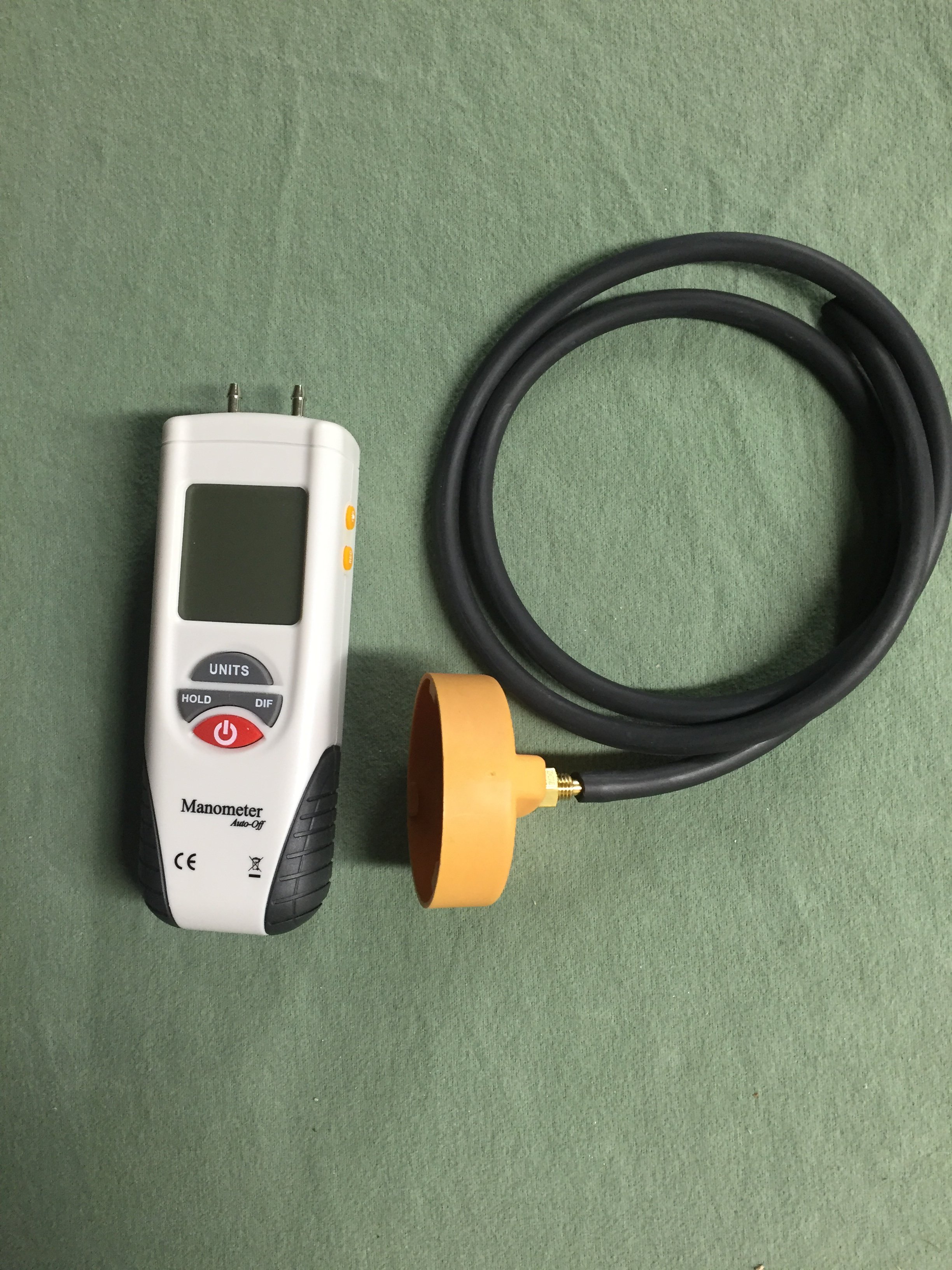
If the oil cap is hard to remove, you have a high vacuum level in the sump, which is bad for a variety of reasons, including lean stalling. The correct way to access the AOS is to fully warm up the engine by driving the car for 10-15 min, then replace the oil cap with the one in the picture above with a hose that connects to the digital manometer. If the vacuum level exceeds 6-7 inches of water vacuum, the AOS is leaking air into the intake system, causing the lean stall conditions. The normal level of vacuum is typically 4-5 inches of water, which is a really weak vacuum level, so it doesn't take much of a leak to cause problems, which is why we always checked every car that passed thru the shop with the manometer.3 points
-
The AOS can either be pin pointed or eliminated by having the car's sump vacuum level checked with a digital manometer (most quality shops have them as the AOS is a perpetual issue; surprise the dealer didn't do this).
 2 points
 -
Welcome to RennTech If you do not have access to a wiring diagram for the vehicle, probably the easiest way to check the ground is to pull the bulb in the light and use a multimeter to check the condition of the ground at the bulb socket.2 points
-
We have used them here in the US for years at MUCH colder temperature's than you get without ANY issues. Put on the adaptor, add external magnets such as the Filter Mag, and enjoy both better filtration and peace of mind.......2 points
-
Welcome to RennTech The factory radio had a ground wire that had to be attached to the car's chassis under the dash as a simple anti theft device. If that ground is not there, the immobilizer will prevent the car from starting.2 points
-
I recently replaced the coolant pipes in my car. I needed to do the job myself because there was simply no way I was going to shell out anywhere from $1500 to $3500 in labor to have it done by the dealership or an independent shop. Plus, having read about the job, I knew they would be tearing through a ton of stuff and I really feared the "oh, it also needs this" scam. I did a LOT of research on the various forums before undertaking this job. Reading and printing out anything I thought was useful information. I would highly encourage anyone reading this to do the same. Fortunately, I was not in the position that the pipes simply failed and dumped all of the coolant. I just had a semi-slow leak… dropping about a gallon of coolant every two to three weeks. So, I had time to order the parts and prepare. Prior to doing this the most complicated thing I had done myself was change the oil, replacing the brake pads and swapping out some plastic bits in the car. I had absolutely no prior mechanic experience whatsoever. However, I do work in IT, and am by nature a very technical person (I'm sure every mechanic reading this just rolled their eyes). My job is troubleshooting very complex problems on very large networks, and I think that experience probably lent itself to a successful outcome here. I'm also patient, and that is critical to getting this job done. I will say that I now have a much greater appreciation for mechanics and their skill set. This was hard. I want to caution anyone reading this that this is a BIG job and it will take a long time. My goal in writing this is so that my fellow Cayenne owners can be spared a lot of the mistakes I made and be better prepared than I was. I will say I am relieved to have this done. I feel a ton better about my car now that I don't need to worry as much about some catastrophic failure hitting me unexpectedly. One rule that I really appreciated was to only place metal on metal when working (until you actually get to removing the pipes). This prevents you from breaking plastic or tearing rubber with something metal. Trust me, pay attention to that rule. I am breaking this down into tasks, because I think it's easier to follow that way. This is how I did it. I am sure there are other ways that may even be easier, but this worked for me and my schedule. I ended up working 4-6 hours at a stretch in the garage with breaks every couple of hours. Step 1: Contribute to this forum I have absolutely no affiliation with this forum whatsoever other than I am a contributing member. The advice on this forum has personally saved me thousands of dollars, and being in IT I know the time and money it takes to run a site like this. So, contribute to the cause. However, there is a second reason to contribute, and that's to get the Porsche TSBs. The TSB for this job contains some diagrams that give you a better idea how all the replacement parts go in to place, and I thought that was handy to have. As an aside, I searched some other issues in the TSBs and found answers to some things the dealership didn't even know… such as there being a $33 replacement latch for my armrest. They wanted to sell me a whole new armrest for $750. Step 2: Obtain the Parts I looked around on the Internet and called some local sources and found a dealership that provided the parts for $550, and that included two gallons of coolant shipped to my door. To me, that was a fair price, and when I received the parts I really thought it was a fair price... there's a lot of quality stuff in there. I'm sure there may be cheaper 3rd party sources. I would just be sure they include all gaskets and such that don't necessarily need to be replaced, but should be replaced if you're tearing everything apart. Once you get the parts, pull them out of the box and examine them. Look at the pics in the forum and look at the TSBs. Get a feel for what you are replacing. Step 3: Verify you have the tools I found the following tools very handy to have, and frankly, necessary. I suggest going to your local auto parts store for most of them and get mechanic grade tools. Socket Wrench 3" Socket Extension 6" Socket Extension Metric Socket Set Torx Socket Set (think of this as a "male" Torx Socket set, you will need #27 & #40) E-Torx Socket Set (think of this a "female" Torx Socket set) Screwdriver that accepts interchangeable bits (there are times this is easier than a socket wrench) Torx Bit Set (Specifically you need a #27 and #40, I just bought a set) Locking Long Nose Pliers (6" is fine, no need for anything bigger) Regular set of pliers Wrench Set (somewhat optional) Real flat head screwdrivers Very long flat head screwdriver (this came in handy a lot) Needle Nose Pliers Small Chisel Set Hammer Tin snips Safety Glasses Mechanics Gloves One of those extension things with a magnet on the end One of those extension things with a mirror on the end WD-40 Some all-purpose grease, like White Lightning Baggies to store the screws in Masking tape/Painters Tape to cover up any exposed openings Old Bath Towels (used to protect the car) Good flashlight Lint free rags Shop Vac Two gallons of distilled water Drain pan (needs to hold 4 gallons) Shop lights A small block of wood, about 2" x 4" x ¾" A radio playing energetic music of your choice Advil and Tylenol Hope and a prayer (optional but doesn't hurt) Step 4: Book the Time I know some people say you can have this job done in less than 8 hours, but being a beginner this took me much longer. If I took out all the time running back and forth to the store for tools and such, and had a guide like the one I am writing, I still think it would have taken 10-12 hours. I ended up removing all of the engine covers on one weekend night, and then doing the actual job the following weekend. I then drove the car for a week with the new pipes and finally put all the engine covers back on over the weekend (I cleaned the covers and the engine thoroughly with a damp rag at the same time to pretty it up a bit). You don't really need to do it that way, but that split the work up a bit. I work in an office in front of a PC all day; I'm not used to working in a hot garage for 8-10 hours at a time... I'm a skinny computer geek : ) When I did the work, I draped some old bath towels over the sides and front of the car to protect it. The last thing I wanted to do was mess up the paint on a zipper or with a dropped tool/screw. Step 5: Remove the Engine Covers There are really two parts to this. You have the decorative covers over the actual engine, and then you have the covers that border the engine. You'll want to remove all of the covers around the border first. There are five of them in total. They all have these little black plastic plugs that you just turn 90 degrees. They should just pop up at that point, but you might have to give them a little lift with a screw driver. While you're removing those covers you might want to pay attention to how they go together and where they slide in to place. You'll also want to remove the windshield washing fluid cap (use the masking tape to cover up the exposed hole) before you remove the cover that surrounds it. Those little things are $4.25 each from the dealership, so try not to lose them. Now you have the three silver looking decorative covers; one on each side of the engine and one towards the front middle with the engine type on it. First, you need to unbolt the two secondary air injection units. Those are the round things with the plastic covers near the back of the engine compartment. You do not need to disconnect them from anything, just unbolt them (three screws each) and then move them off to the side. It might be a good idea to get some labeled baggies to store the screws in. Once those are removed you can get to the side engine covers a little easier. The engine cover in the front middle you just lift off, just work it back and forth a little and it should pop off. Take note that there are four little plugs that fit into holes on the cover itself, you'll need to find them again when replacing it. Now remove the one on the driver's side. It's pretty easy to remove. There are four screws towards the bottom that need to be removed, and then the cover will just come off. The one on the passenger side is a bit different. You have the engine mount right in the middle of things. Assuming you have the tools, you can unscrew the engine mount and get it out of the way. That will let you get to each of the four screws easily on the cover and remove it. I wasn't so lucky here (didn't have the right tools at the time), so I just got the four screws out of the cover and ended up wedging it out. While doing that, the piece of the cover under the engine mount snapped off. I wasn't too concerned about this, because where it snapped is hidden by the engine mount. When I put everything back together I just slid it back and screwed it in. You can't tell at all that it was ever snapped in half. Step 5a: Remove Fuel Pump Fuses You'll want to check your manual (you can also download the manual from this site), but you need to remove a couple of fuses for the fuel pump. Right in front of the driver under the hood there is a small compartment. Remove the cover, and then remove a second cover to expose the fuses. Mine were fuse 14 & 15 for the fuel pump. Store them somewhere safe. Once those are removed, start your car. It will run for a few seconds and die. Congrats, you just removed most of the fuel from the fuel line. I know some people don't disconnect the fuel rail or anything, but to me that's a bad idea. I had a lot of time to try it that way and honestly I'm glad I got it out of the way. Step 6: Disconnect the fuel line The fuel line is near the back center, it's just one tube running to the fuel rail. You'll disconnect it by using a wrench and a pair of pliers. You're unscrewing the part on the left (the thin part) from the part on the right (the wide part) which shouldn't turn as it is part of that tube. Once unscrewed, the fuel rail is only connected to the manifold. A little residual fuel might leak out, so you might want to have a rag handy to wipe it up with. Use masking tape to cover up any exposed holes. It wouldn't be a bad idea to disconnect the batteries now either. I didn't, but that was probably stupid. Step 7: Remove the Y-Pipe that goes to the Throttle Body This plastic Y-Pipe is right up front so it's very easy to get to. There are two flexible pipes on either side you need to remove first; just use a screwdriver to loosen the two clamps on each of them and you should be able to compress them enough to remove them. The Y-Pipe itself is attached to the throttle body via two long, plastic bolts. They have a screw head on them but they are not screws, they're more of a key. You just turn them a bit to line the key at the bottom (use a flashlight and you'll see it move as you turn it with the screwdriver) with the slot. When it's lined up, use a pair of needle nose pillars to lift it straight out. It's plastic and may be brittle, so be a little careful. You will need to remove an electric connection to the throttle body in order to get to one of them. There is a tube connected to the bottom of this y-pipe, so you can't just lift it out. It has some give to it, but not a lot… just enough to get your hand under there once you pull the y-pipe off the throttle body. You have to press the buttons on each side of the tube in order to get it off the y-pipe. Step 8: Remove Emission Tubes & Electrical Connections from Throttle Body There are two emission tubes crossing the throttle body, Porsche refers to them as "vent tubes." I know this because one snapped in half when I removed it, and the dang thing was $130 to replace. To remove them, you just need to press the clips at either side of the end of the tube together and then pull it straight out. I don't think mine had ever been removed, and in retrospect a bit of WD-40 used sparingly here might have been a good idea. I think I used too much force and that's why the small one snapped. I have read that some people have replaced this broken tube with a more generic tube from a hardware store. I just spent the $130 and did it right. There is a third tube connected to the throttle body, you just need to remove that one end of it. You will also have two electrical connections to remove. One you had to remove to get the y-pipe off in the previous step. Just remove the second one and then you're done. Step 9: Remove the Throttle Body The throttle body is connected to the manifold via four bolts. Remove those four bolts and it will come off. You sort of have to wiggle it out because of that thin metal bracket that's holding it there, but it will come out easy enough. Some people take this opportunity to clean it. You'll probably see some gunk on the back side of it on the inside. Step 9: Remove the Electrical Connections to the Fuel Injectors There are eight fuel injectors connected between the fuel rail and intake manifold. Mine were blue plastic, and there is an electrical connection running to each of them. There is a metal clip at the bottom that you just need to press up. I placed a flat head screwdriver between this clip and my index finger, and pushed up and pulled at the same time to disconnect it. Once you remove one you'll get the trick and the rest will come right off. Step 10: Remove the Intake Manifold with Fuel Rail Attached I know a lot of people have different ideas here, some people want to remove the fuel rail independently, and that was the first way I tried it. In retrospect, it's much easier to just leave it attached. There are four screws that hold the fuel rail to the intake manifold. I would recommend leaving these alone, especially since the one at the back on the passenger side is nearly impossible to get to. These screws are $6+ each… I know because I lost one. :P There are 10 bolts that need to be undone to remove the manifold. They don't come all the way out, they'll stay attached to the manifold. Once you loosen them enough they sort of come free and wiggle around. The one at the back on the passenger side was a bear to get to. I ended up placing the Torx Socket bit on top of it using the magnetic extension thing. I then put the 3" extension on top of it, and finally attached my socket wrench to it. I kind of built it all up I guess. I then went really, really slowly and loosened it up. Once loose, make sure to vacuum up any debris on the engine. When you pull the intake manifold off you will have eight gaping holes right down to your cylinders, you don't want anything falling in there. You can now scoot it forward a bit to get to the tubes you will need to disconnect. There are two tubes at the back of the manifold… a firm one and a flexible one. The firm one is just like the one under the y-pipe, and is easy enough to remove IF you can get enough pressure on the connector. The flexible one was just kind of stuck on mine and I left it on. You kind of have to scoot the manifold forward and angle it out, but it will come out with the fuel rail attached. You may have to remove some tubes and such from their guides or brackets. That flexible tube was long enough that I just put the whole thing on the driver's side of my engine and left it there. It didn't seem to be sitting on anything that couldn't support it. I'm sure it can be removed, but at this point in the job I was tired, hot, and just wanted to keep going. Once off, IMMEDIATELY cover up the exposed intake holes with long strips of tape. Cover them completely, and make sure they STAY COVERED. Shine a flashlight in each hole first to make sure nothing fell down there. If so, get it out as delicately as possible. Vacuum up any other debris you see. You can now see the infamous coolant pipes. Step 11: Assessment At this point, you can see the coolant pipes and should be ready for the meat of this repair. The starter is right there too… right under the leaking pipes. Brilliant, isn't it? This may not be true for you, but I had an AMAZING amount of debris in here… honestly looked like a bird had built a nest. I have no idea how it all got in there, but some where at some point tons of debris got in here, and now it was all soaked in coolant. I think my coolant leaking may have been mitigated because the wet debris probably acted as a mud and sealed everything up a bit. I vacuumed it up with a shop vac prepped for a wet cleanup. Now you need to decide if you will see this repair through or not. Once the next step is taken, there is no going back, and honestly the toughest part of this job by far is getting the old pipes out. Step 12: Drain the Remaining Coolant Your first goal is removing as much coolant from the car as you can. On the V8's, there is a drain plug at the bottom of the car, but on the turbo's you won't have one. That drain plug required an allen bit that was larger than I had on hand or could even find at a hardware store. Honestly, in retrospect I wouldn't have even bothered locating it. I'm sure there's a pipe down there you could remove, but I didn't waste time looking for. I took a tip I found on a forum, and drilled a hole right in the middle of the center coolant pipe (of three) and used a siphon with a hand pump to drain out every bit I could. I repeated this process on the larger lower pipe. DO NOT SIPHON BY USING YOUR MOUTH. Coolant is dangerous, nasty stuff. Make sure there are no animals or kids around while you are doing this. WEAR SAFETY GLASSES AT ALL TIMES! Doing it this way you're going to spill a lot of coolant, but it is what it is… they've been leaking all over everything anyway. I used my shop vac to vacuum up anything I could that escaped the siphon. I've also read of people renting professional vacuum pumps to suck it all out, but again, that's more complicated than it needs to be. I did some research, and coolant is not currently controlled by the EPA for disposal, and it can't be recycled. The unofficial advice I got was to dump it in the woods and douse the area with a hose for a bit. Do not dump it down the drain or dump it where animals could readily drink it. Don't dump it in a stream. Presumably it breaks down fast enough on the ground that there isn't a long lasting effect. Step 13: Remove the Three Upper Coolant Pipes The first pipe you need to remove is the long skinny pipe with three connectors. This one is easy enough to remove, and you should have a replacement as part of the kit. One of the connectors broke off in the hole, and I had to very carefully remove the pieces. Relatively speaking this was easy compared to the rest. There is a compression ring that needs to be removed for the connection at the back of the engine, use the locking pliers to do that. Cover up the exposed holes with masking tape. You now have to remove the three upper coolant pipes. There is a bracket at the back of the engine holding the three pipes. There are also two clips attached (you'll be looking at the back side of them) to that bracket that just support a hose at the back (just has electrical connections in it, and it's probably already split so you don't have to be super careful). Pinch the connectors with a pair of needle nose pliers and they'll come off. You now have to remove three bolts from it to remove the upper half of that bracket. I removed two of them but couldn't get to the third without snapping the thing in half. Porsche was kind enough to provide a new one in the kit so I wasn't worried about it. You will now see three rubber hoses attached to the plastic pipes. They are held on to them with compression rings. Use the locking pliers on the rings to loosen them (they need to be squeezed together to loosen) and slip them back over the pipes. I did one at a time, completely removing the ring and setting it off to the side for safety. The locking pliers really excelled here. When using them, attempt to come at the ring from the top instead of the side, the grooves on the pliers will then secure the ring quite nicely. You might have to adjust the pliers a couple of time to get the right amount of the compression for the ring to move freely. With those ends free, I used the shop vac to suck out a lot more coolant. Once done, cover up the exposed holes with masking tape. Once those three ends are free, you'll need to free up the other ends. Here's the deal, they are probably going to break when you try to remove them, and probably going to snap off at the spot where they connect to the coolant reservoir. I twisted and pulled and sure enough, they snapped off. You can remove the lid of the coolant reservoir by removing several screws, a small aluminum pipe on top, and the rubber pipes towards the front of the car. The small aluminum pipe has a single screw that needs to be removed. There is probably a lot of corrosion here so you may need to use a flat head screwdriver to pry it out. Be careful, it's flexible enough to come out and get out of the way but just barely. There is a compression ring on each of the rubber pipes that is easy enough to get to, just loosen and slide it down the pipe. Suck out any coolant and cover the exposed pipes with masking tape. Once you have that lid out, you'll see the remaining plastic bits in the holes. It's difficult to move, but those plastic bits are just in there with pressure, they aren't glued or anything. I used a small chisel and the hammer to break them out. As I got to the o-rings I pulled on those with needle nose pliers and in one instance the whole chunk came out. I also used a lot of WD-40 to work everything out. What you don't want to do is take any risk of chiseling into the metal of the lid, so be careful. This is all about removing the plastic material. Each bit you remove gets you one step closer to freeing up enough pressure to get the remaining bit out. Once it's all clean, leave it off to the side while removing the big pipe. Step 14: Removing The Big Pipe This one is tough. Make sure you're rested, well fed, and cooled down a bit. If you're aggravated already, walk away and relax a bit. You will need to break this pipe into two pieces. I used a boring bit to drill a big hole in the top, and then used tin snips to cut chunks out until I got it in two parts. Again, I used a shop vac to suck out any remaining coolant as I went along. Really, anything will work… you could even use a chisel to break it out. It's coming out one way or the other, no need to be pretty about it. Once it's in two pieces, you can probably rotate the two halves apart. Use WD-40 generously on the ends first though, and give it a bit to work in there. Regardless, when I went to pull out the two ends, they ended up snapping off… leaving their end pieces in the hole. If you read through the three forums, different people use different techniques to try and avoid this with mixed results. This is the worst case scenario though, so lucky for you I fought through it and have plenty of advice. Assuming your pipe broke off as mine did, you will see a metal ring in each end, with black plastic between it and your car. That metal ring was an inner support ring for the original pipe and needs to be removed. This is a violent procedure. IMPORTANT: I cut up some lint free cloths and stuffed one into each end as far as I could so that any material from the following procedure wouldn't go any further. Once done with the procedure below, I vacuumed up anything I could and then removed those cloths. Again, use WD40 a LOT. I sprayed and sprayed as a worked, and I think it helped. READ THIS CAREFULLY: Removing the plastic and metal ring from each end is all about removing material. You are trying to get as much plastic out as possible. If you get the ring out first, great, but it's not 100% necessary. The plastic is what needs to come out, and you need to get it out from all around it. In addition to the plastic, there are two o-rings in there, so they are just adding more friction preventing this from moving. You'll get bits of that out as you work, and that's good. Eventually, you get enough bits out that the rest will just fall out. Use a hammer and chisel to collapse the metal ring on the top and sides as much as possible. I used to the chisel to cut in to it a bit too. Once I got it that far, I switched to the long screwdriver, hammering the end of it into the plastic over, and over, and over again. I pried as much as I could and worked out bits of material. This took a long time, but sometimes you'll get a big chunk out and that will give you renewed hope. Again, this is all about material removal. Keep telling yourself that. Every bit you get out makes this easier. Once you get enough plastic out, you'll see the metal ring move a bit as you work. This is a great sign and you are almost done. Ultimately, you should be able to pry it out with the screwdriver. NOTE: When working you want to work as much towards the metal ring as possible. You want to avoid scraping the inside of the hole where your new pipes will go. I did scrape up mine a bit, it's unavoidable, but regardless my new pipes don't leak. When you go to remove the bits closest to you, you're working somewhat blind and it is hard. This part almost broke me, but I used a mirror to check and recheck my work as I went along. Bright lights help here too. Honestly, I really can't say enough how hard this part was and how long it took in comparison to everything else. It was the part that had me the most worried, but I got through it. Once it's all out, remove the cloths from inside the pipe and vacuum a lot. Now is the time to clean stuff up too, as you're about to put the new pipes in. As a best practice, you should clean up the inside of those holes. I used some steel wool; I know some people used scotch bright or even buffing pads. I didn't go overboard with this; I just want to get any grime out of there. Step 15: Install the New Big Pipe At this point you should be elated. You're through the worst. Installing these pipes are a bit difficult, but not bad. If they are not already on there, put the O-Rings on the small pipe. Use the White Lightning grease or whatever you bought and coat the inside of the hole on the engine and the outside of the pipe. Use it liberally. A bit of WD40 wouldn't hurt either. Press it into the hole at the back of the engine and do your best to get it all the way in. This is where a small block of wood and a hammer come in handy; you can use those to tap it in the rest of the way. Do not put the rubber sleeve on it. For the big pipe, install the o-rings and lube everything up good with the grease, both the hole it goes in and the pipe itself. You will also need to grease up the end the rubber part goes on and the other end of the short pipe that the rubber sleeve will slip over. Place the tightening rings over the rubber sleeve as well. Slide the rubber sleeve as far as it will go over the pipe. Push the pipe into the hole, I found a twisting action worked well. I also used my metal screwdriver against the bottom of the engine bay as a lever to slide it in the rest of the way (it required a lot of pressure). You then need to rotate it to line it up with the short end of the pipe. You'll slide the rubber sleeve over it and then tighten up the two rings. NOTE: Be sure to rotate the rings as far down as possible so that the screw does not interfere with the three pipes you're about to place on top of it. The new big pipe should be in place, and you're now done with the hardest part of this job. Step 16: Install the Three Pipes You'll want to put the lid back on the coolant reservoir (replacing the seals Porsche included with the kit), reattach the pipes and tighten up the screws. DO NOT OVERTIGHTEN THE SCREWS. I snapped one clean off. Make sure they're tight, but don't put all your muscle into it. Once on, you are ready to slide those pipes in. You do not need to put the lower bracket at the back on first; I did it after installing the pipes. Again, make sure everything is lubed up well so that any points of friction are well covered. Slide the pipes in. I used by long screwdriver again as a lever to apply the necessary pressure. On both these pipes and the big pipe it looked like I could have gone another 16th of an inch, but nothing leaks so I guess it was far enough. Put the bracket on at the back before you attach the hoses. You'll use your locking pliers again to attach the compression rings. With the bracket in place it is obvious how far up the hoses go. You'll put the upper bracket on, using the spacers for the screws and screwing it down tight. Don't forget to attach the two brackets that hold that electrical cable in place. Not a big deal if you do forget. Step 17: Install Final Pipe Now install that skinny pipe. This one is easy. Don't forget about the small compression ring that goes at the far end. Everything else just clips in. Step 18: Assess Your Work Look over everything and make sure it all looks right. At this point you should have a sealed coolant system. Check all your connections and make sure everything is solid. At this point you're home free, and you should be feeling pretty darn good. Step 19: Fill Up Coolant I use a 50/50 water to coolant ratio… so I mixed everything up with what I had and filled up the coolant tank. Once it was full, I left it overnight and checked in the morning for any fresh coolant. I was totally beat from a long day of working on it and thought putting everything back together fresh in the morning was a good idea. Step 20: Put Everything Back Together You tore it apart, now put it back together. I cleaned everything as I went, so now my engine looks great and I think that's a good idea. You don't need to go overboard, just use some lightly damp, lint free rags and wipe everything down. Porsche should have also provided new seals that go on the bottom of the intake manifold. I replaced mine dutifully, and I am glad I did. The old ones just looked worn out, no way they weren't leaking. Putting everything together is pretty straightforward once you've taken it apart. Just be careful and make sure you get all electrical connections and hoses in back on securely and in the right places (hard to mess that up). Also make sure you remove every bit of masking tape as you go. Final Thoughts I am very, very glad I did this project for two reasons. One, it saved me a ton of money and two, I now know tons more about the engine. Doing this project means I could replace my fuel injectors, spark plugs, injection coils and a host of other things when and if I have to. I know where the throttle body is, and if it's sticking I know where to go to clean it. If I need to replace the starter, I know where it is and how to get to it. I can now take my car on trips without fear of a massive coolant leak. This was the last "major" Cayenne defect for me that needed to be fixed. The water pump & drive shaft were already replaced. With 116,000 miles, I have quite a bit of faith in my car not having a catastrophic failure (knock on wood). At the end of the day, I'm pretty proud of myself for getting this all accomplished, and I hope I've saved some other poor soul a ton of time by writing all of this down. If it does help you out, please reply to this post and let me know.2 points
-
On occasion during the most humid months of the year, the air coming out of the vents of my nearly 8-year-old car would smell a little 'off.' Since the a/c condensation was draining just fine and the odor wasn't ever-present, it wasn't a major concern to me. However, surfing the web I found a variety of A/C refresh kits that seemed worth a try, if for no reason other than to experiment and see if it was any benefit. But, no good deed goes unpunished. There are a variety of kits out there, some seem OE but most are aftermarket. I found them to have so much in common that I began to think they were made by only one or two manufacturers. The kits I was considering are two products: 1) a foaming spray that you inject into the evaporator housing through the condensation drain, and 2) a spray that you empty into the external air intake while changing the HVAC settings. The kits state or imply that they will clean the evaporator of crud that comes from dirt, mold, mildew, etc. and kill whatever causes odors in the venting. As I mentioned, the kits seemed nearly identical to each other so I bought one based on convenience at a local parts supplier for about $18. For another point of reference, there is a Toyota kit, part number 00289-ACRKT, that you can find here for instance. The product I used was the following: Note: This attempt to clean an HVAC system was for my particular 2003 986S. Other vehicles may be different and there are safety risks involved in doing mechanical or electrical work on a vehicle. What's presented here is a general overview of my DIY project, not a complete step-by-step set of instructions. Please obtain, understand, and follow the necessary repair and installation procedures in order to work safely, avoid damaging anything, and achieve a safe result. Preparation steps: I raised the vehicle up onto four(4) jack stands. Then I loosened or removed numerous underbody panels to expose the area under the passenger side floor pan. The location of the condensation drain is identified by an arrow in the photo below: First use the larger can of "evaporator foaming cleaner." You can read the instructions on the can in one of the photos above. I had to use another piece of tubing between the tapered nozzle and the condensation drain because the drain tube is not flexible and wouldn't hold the nozzle. That should have been the first indication to stop. Notice the grommet around the drain tube in the photo above and how the tube is inconveniently situated between the hot water supply/return for the heater core. As I was trying to force the tubing onto the drain, I pushed the drain tube and grommet into the passenger compartment. I knew it was going to be a pain to put it back, and it was. I had to remove the umbrella trim along the passenger-side door threshold, loosen the floor carpeting, and shove my arm under the carpet to reinstall it. Photos of the attachment and foam injection below: The foam went in, it seemed to sit for a while, it liquefied a bit, and then it drained out. The photo below was taken at a moment just as it was starting to drain: The liquid in the bucket was mostly clear, with a little particulate matter--nothing worth photographing. It didn't have much of a smell; it was slightly medicinal, like disinfectant. Following the instructions on the can, the next step is to use the "a/c intake refresher." Take out the pollen filter and spray into the air intake. You are supposed to change the vent settings between spraying intervals so that the mist runs through different duct work. Again, it has a slight disinfectant smell--pleasant but not flowery and not too strong. Not too bad, right?... Well, I was too preoccupied with the camera to realize what was happening inside the car: After all the effort for something that wasn't really necessary… I had to laugh. I was doing this process as I was preparing the car for winter storage. It was about 40° F (4° C) in my garage. Obviously, a lot of the foam didn't liquefy and drain. If I were to do this again, I would warm up the HVAC system beforehand, or just do the whole process at a higher ambient temperature. I'd also let the evaporator core drain longer (a lot longer) before doing the 2nd can. The photos above are the worst of it; only a little came out of the other vents. I blasted the system for a long time after that and it cleaned up without a problem--no damage to any surfaces. A few days ago I fired up the car for the season. No issues. Live and learn and pass it on. --Brian2 points
-
1.) Un-screw the one phillips head screw at top center of side air intake... 2.) The molded air duct and the intake grill are still attached by three delicate plastic tabs at the three points... The best way to remove this is gently insert your fingers through the grills into the intake at the points circled in red and gently try to free the tabs... All three points come forward towards you, but if one is stuck or gets caught it will break... 3.) Inside the drivers side air duct you will find a snorkle... The snorkle is added to most US cars for noise restrictions. Now this piece is attached by no screws or tabs, but it most likely will give you some troubles removing... The best way is to remove this, just grab a hold of the long snorkle (not the small dish on the end)... Now wiggle it from left to right and vice versa while pulling out towards you. This works, but might take a little effort. 4.) This is what the intake is going to look like after the snorkel is removed... Just carefully insert the three tabs back into their points... Make sure that all three are tightly in by pushing the airduct cover (not the grill)... Insert your 1 screw into top center of cover and you are done.2 points
-
Be sure to use some protective material on the mirror base. Set the pliers with the protecting parts to the windshield to the diameter of the mirror base and secure to the mirror base. Turn the rearview mirror through 90 degrees at the mirror base using the pliers. Then, unclip the base of the interior rearview mirror from the retainer plate on the windshield. When you reinstall the mirror be careful not to go beyond the 90 degrees locking point. If you remove the mirror base from the windshield you will need a special cleaning/glue kit from Porsche to reinstall it.2 points
-
2006 CAYENNE 955 4.5 V8 DRIVER SIDE PRIMARY CAT REPLACEMENT Full size pictures can be found HERE Writing this down hoping it can help out another pepper owner. SKip to the bottom if you want the short version. Had to replace the drivers side (LHD) primary catalytic converter as the flex pipe had completely corroded away and was flopping loose in the wind. I got lucky and found an aftermarket one on eBay for significantly less than what the dealer would charge me. You’ll need an assortment of tools for the job: Jack Jack stands Ramps for rear 10mm sockets 12mm sockets 13mm sockets Numerous extensions Wrenches in above sizes and flex head ratcheting are awesome 22mm O2 sensor wrench or crowfoot Straight ⅜” and ¼” ratchets and breaker bars for extra leverage as needed. Flex head ⅜” ratchet Long flathead screwdriver to open up the clip holding the O2 sensor wire T25 screwdriver or bit for your screwgun for trim pieces #2 screwdriver or bit for your screwgun for trim pieces Total actual work time was about 8 hours. I could have done it in about 5 or even less if I was truly ambitious, but was taking my time and making sure I didn’t break anything in the tight space. The time also included jacking up the car, removing the underneath skid panels, engine compartment plastics, drivers tire and wheel well liner as well as reinstalling them. See Pelican Parts for the skinny on accomplishing all of those tasks. I’ll skip those tasks here. https://www.pelicanparts.com/techarticles/Porsche_Cayenne_Tech.htm Also crack open the rear hatch and block it from locking as you’ll want to disconnect the battery ground. Here is a video that shows how. Super easy and never knew myself. No need to flip the seat. How to disconnect battery ground in Porsche Cayenne (955) I will preface my replacement with the added bonus of the car having the secondary CAT delete already done. So no fighting with those. So under the car, first things first was loosening up the connection between the tailpipe section and the straight pipe, which was connected to the primary CAT. As the existing bolts on the CAT were rusted and frozen, I just snapped them off knowing they would be replaced anyways. Don’t waste your time on PB Blaster or heat. Just break them off and be done with it. So with the easy work complete now it’s time to dive into the fun part. Move up under the car so you’re looking straight up where the CAT meets the exhaust manifold. You’ve got 3 bolts above you that you’re wondering how you’ll ever get to them without taking out the front O2 sensor and even then how. Give them a spray of PB Blaster or your choice of penetrant. Now move to the front of the car in front of the sway bar, there is an opening where you can see the 3 nuts on the exhaust manifold. With a combination of extensions you can reach the nuts with a 12mm socket. You can let them soak for a little while as you have another cup of coffee or beverage of choice. At this point you may be wondering why I haven’t mentioned the O2 sensor on the top of the CAT pipe. Well, because I drove myself crazy trying to figure out how to get it out. I went after it 8 ways to Sunday. From the top with swivels and extensions and the same from underneath. I could barely get a finger over it and did manage to get the socket on it but then couldn’t get it broken free as the leverage just wasn’t there, or the socket/crowfoot slipped off. Needless to say, I wasted about an hour or so on this and questioned my seemingly foolish decision to approach this project. In the process of doing all of this, I figured out I needed to remove the middle skid plate support bracket for more room to reach up in the small area. Working by myself created new opportunities to be resourceful, or stupid depending on point of view. Since I was already committed to this endeavour by already removing, AKA breaking, the lower sections of exhaust piping, **** the torpedoes and full steam ahead. I ended up just unbolting the CAT from the exhaust manifold, dropping it down and slightly rotating it. At that point I had a good view of the O2 sensor and slipped the O2 sensor socket right over it with a breaker bar attachment. With the room to get leverage and a straight shot at it, it came loose with a marginal amount of effort. Unscrewed the sensor by hand and pushed it behind the steering column. Now for the next problem. The CAT was just big enough to not slide out with the heat shield of the steering column shaft in place. So, prop the CAT in place and remove the heat shield (2-10mm bolts), giving that extra ¾ of an inch. And so with a small amount of finagling, out she came. Could I have worked a little more on it and fought it out? Maybe. But for two 10mm bolts, easy choice. At this point in time, I called it for the day as I was now about 5 hours into the whole job. Sunday morning - here we go for part 2. Now knowing how it came out, it should make it easy to go back in. And yes, it was. Reverse the process of the removal. Slide the new slimmer CAT up into the general position it needs to be, let it rest on the other parts while the O2 sensor is installed. I did unclip the connector up in the engine bay and hang it from the hood so it would spin freely while installing it. A tip I saw elsewhere, thank you. Now push the CAT up into position and viola!. NO! WAIT! The mounting bracket is farther forward than on a stock CAT by about a ½ inch and slightly rotated off the axis of alignment from the engine bracket. The CAT won’t go all the way forward to mate with the exhaust manifold. So… Now it’s pushing, rotating and mild cursing to get it around the engine bracket. In the end, I got it together. Final decision on the bracket, it’s staying unbolted. Not the preferred method, but that’s how we’re rolling since I don't have a welder anymore to move the bracket on the CAT. At this point I was able to get my hand up to get the nuts on the ends of the bolts and finger tight them. Slide around to the front with the long extension and reach in to tighten them up. Now, if you’re lucky, you may have an air ratchet or a battery operated ratchet, which I did, to tighten them up. Do so at this point. Back to the middle of the car to reinstall the short pipe piece to the flex end of the CAT and to the tailpipe. Reinstall the middle skid plate support bracket and you’re just about complete. I hope for all of you who lasted this far have good luck getting around the secondaries if you still have them or figure an alternate plan for that. Time to start the car before I put everything back on and drop it to the ground. Hook up the battery (sparky, sparky), key in the ignition, hand pushing the brake AND… nothing. PANIC!!! I know there’s power. The interior lights come on, chime is going ding-ding. Again.. Nothing. Hold on, let’s breathe a second. Oh lord, the wife will kill me if I killed her car. 3rd time, small prayer to Stuttgart and… SHE LIVES AND BREATHES!!! And much quieter too. Do a couple of start-stop operations to double check it’s all working and then off to reinstall all the plastics and drop her to the ground. I will say, fighting to get the wheel liner on, is an extraordinary test of patience and will power. I think I fought that alone for over 30 minutes. If anyone has tips for that process, I’d be eternally grateful. Couple of side comments on this. The CAT I purchased was an aftermarket unit I got off of eBay and have no idea who manufactured it. There were no studs in the flanges, just 3 bolts and nuts per flange. I was worried they were going to fall out during the install, but the new gaskets held them in place as the holes were the right size to screw the bolts through them by hand. I know this helped during the reinstall and not having to bend or cut off the bracket on the CAT. For the heat shield, some places had said to unbolt the steering shaft and move out of the way entirely. I did not want that headache to do a realignment of the shaft/steering wheel. So I just did the minimum I thought would work. Now that you’ve gotten to the end of my story, I hope it will give someone else the courage to take on the project. Take your time, step back, breathe from time to time and don’t rush it. It will happen. Please make sure to tip your waitress. SHORT VERSION Put car on jackstands or at least front end Put rear of car on ramps if only jackstands in front Disconnect battery Remove front left tire Remove wheel well liner Remove underbody skidplates/plastics up to bumper Remove heat shield from steering shaft Remove middle skidplate support bracket Unbolt/snap off bolts from primary CAT flex pipe to tailpipe/secondary CAT Remove short tailpipe section if secondary delete performed From front of car, reach in and unbolt the 3 nuts holding primary CAT to exhaust manifold Drop CAT down and rest it on car Using O2 sensor socket, reach up into area and remove sensor Pull CAT out of car Push new CAT up into the void and rest on car Install O2 sensor Push CAT up to exhaust manifold and bolt together Install engine support bracket (if applicable) Install tailpipe section to flex pipe end of CAT Install skidplate support bracket Install skidplates Install wheel well liner Install tire Lower car to ground Install engine compartment plastics Reconnect battery Start car CELEBRATE Now if someone can share an easy way to do the passenger side......
1 point
-
It that a plug or plastic pop rivet? I am only finding the plastic rivet.1 point
-
See if any of the fault codes have changed. If not, then I would still go the path based on the FRAU readings.1 point
-
P2189 Lambda control adaptation FRAU (lower load range) (FRAU > 0.7) - below limit value Possible fault causes - Incorrect main filling signal from hot-film mass air flow meter - Fuel pressure too high - Injection valve faulty (dripping) - Tank vent faulty (does not close completely) P2189 Lambda control adaptation FRAU (lower load range) (FRAU > 1.3) - above limit value Possible fault causes - Intake system leaking (secondary air) - Incorrect main filling signal from hot-film mass air flow meter - Leak in exhaust system - Fuel pressure too low - Fuel injector faulty (stuck) - Fuel pump delivery too low P2187 Lambda control adaptation FRAU (lower load range) (FRAU > 0.7) - below limit value Possible fault causes - Incorrect main filling signal from hot-film mass air flow meter - Fuel pressure too high - Injection valve faulty (dripping) - Tank vent faulty (does not close completely) P2187 Lambda control adaptation FRAU (lower load range) (FRAU > 1.3) - below limit value Possible fault causes - Intake system leaking (secondary air) - Incorrect main filling signal from hot-film mass air flow meter - Leak in exhaust system - Fuel pressure too low - Fuel injector faulty (stuck) - Fuel pump delivery too low1 point
-
Try 97861 point
-
That's trouble. Recheck connections. Use Deoxit on the plug-in connectors. Use fine grit sandpaper (and clean off the grit left by sanding) on the nutted connections. Is it possible you shorted something out as you removed the battery? Were the battery cable ends removed at the battery? Is it the original alternator? It might be possible that it's only the voltage regulator module.1 point
-
Try 45051 point
-
Try 07581 point
-
1 point
-
Try 69091 point
-
Try 30981 point
-
Lost Radio Codes DO NOT START A NEW TOPIC FOR A LOST RADIO CODE. DO NOT EMAIL ADMINS. Please read the Lost Radio Code FAQ FIRST before posting - then post in the one thread. This topic is closed.1 point
-
Try 50481 point
-
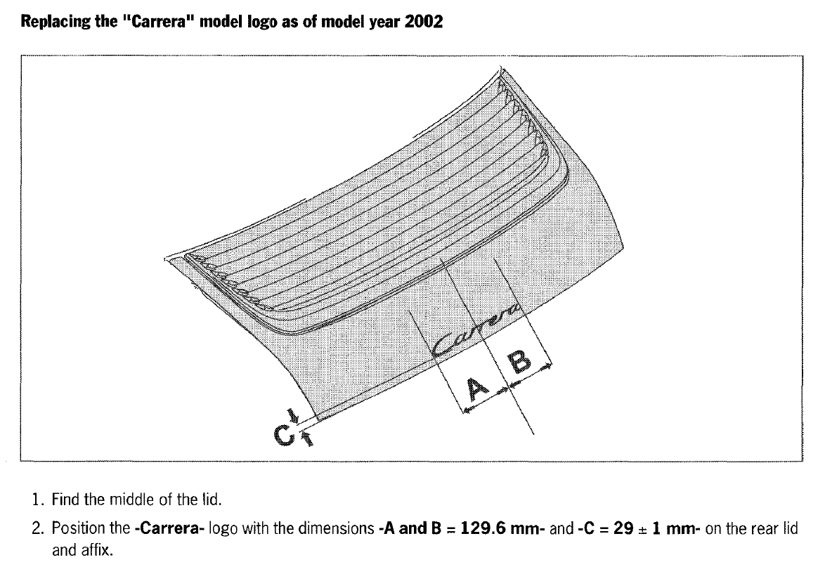
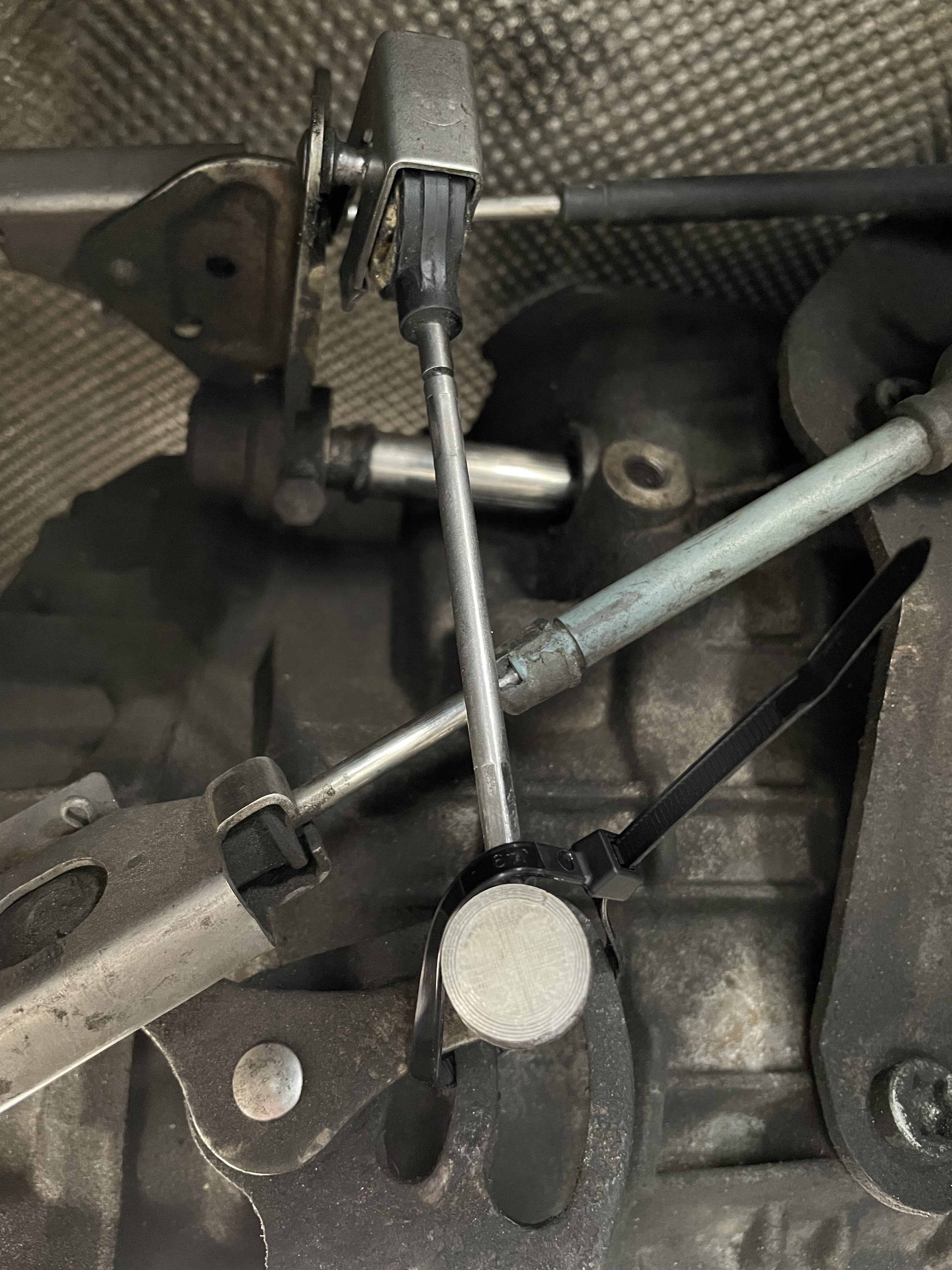
I came across this old post in a Google search and thought I'd provide an update. The Porsche part number for the adjustable linkage is 986-424-931-06 and is available from Pelican Parts for about $250. Numeric Racing makes an all-metal version for $130. The adjustment procedure for the adjustable-length linkage is available in the Porsche OEM Service Manual.1 point
-
I've been receiving this code and trying to run it down. The car runs as expected, and the only issue is that it is difficult to fill (pump shuts off almost immediately unless I fill it very, very slowly). It seems likely the two are related, but that's unconfirmed. In researching the code, it seems most have the "Pressure Sensor / Short to B+" code variant, not "Pressure Sensor / Switch High". The one post (6speedonline) that had a similar code was resolved by discovering a mouse ate the wires. That's possible, but I cannot see any evidence of this, and the circuit seems to be in tact (though if you have a testing suggestion, I'm all ears). With the code combined with the fuel fill issue, my working assumption is that it is the tank vent valve stuck closed. When researching that issue, I see that pretty much all results I found were folks encountering a valve that is stuck open - they get a whistle and maybe a CEL code for low pressure. Any advice, tips, or diagnosis methods?1 point
-
Try 63981 point
-
Try 06871 point
-
Try 90981 point
-
Sorry, my typo try 95101 point
-
I think I know what happened here! I piggybacked the original poster, Andrew Howell, and he was getting the "immobilizer not ready" warning! I think we are back on track here! As in the quote that I have attached reads, you initially suggested that I check the fuel pressure and delivery rates. It went a different direction when you thought there was something in the tachometer being off and that's where the CPS fix came into to play. I understand your mixup because your tending to a lot of different threads. Moving forward. I did purchase a fuel pressure kit. Where is the fuel pressure rail? What readings should I be getting for the fuel pressure and delivery rates? I have never performed this test before. All new stuff for me, but rewarding and going through the steps. By the way, I just donated again. I do appreciate you, JFP and this site!1 point
-
The valve lift system, like the Vario Cam system, are hydraulicly operated using the engine oil pressure network. One of the biggest problems with all of these systems is that they were designed with very small oil passages, making them very susceptible to problems with particles of debris in the oil blocking the passages. The fact that you found debris in the valve lift screen points to where the issue probably lies.1 point
-
Found the solution, the circuit board inside to control unit was corroded at the power input, cleaned resoldered and now working! That’s saved a fair few pounds, just all the trim to put back1 point
-
Just now figured it out on my ‘09 C2S Step 1. Press Info button Step 2. Press Option button Step3. Click the on screen option ‘Set PCCM System’ Step 4. Click the on screen option ‘Reset’ Step 5. Click the on screen option ‘Vehicle hand over’ (did not choose factory settings as did not want to rick loosing any version updates ir messing something else) Step 6 and 7: select Yes for confirmations to proceed. All devices should be gone now plus any other data like phonebook and navigation addresses. you may also notice that in the Source menu, some options like AUX/iPOD etc have also disappeared. Go to Source: Select ‘Disc’ (have to have a disc inserted and car engine running), then click Options and it takes you to a menu to select various sources to select and display in the Source menu Hope this helps. Good Luck1 point
-
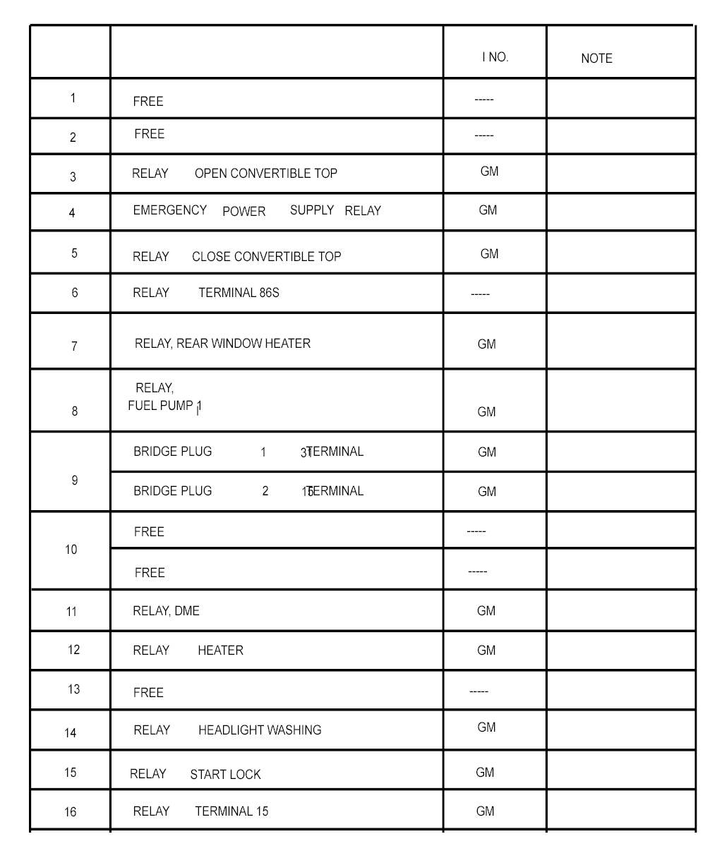
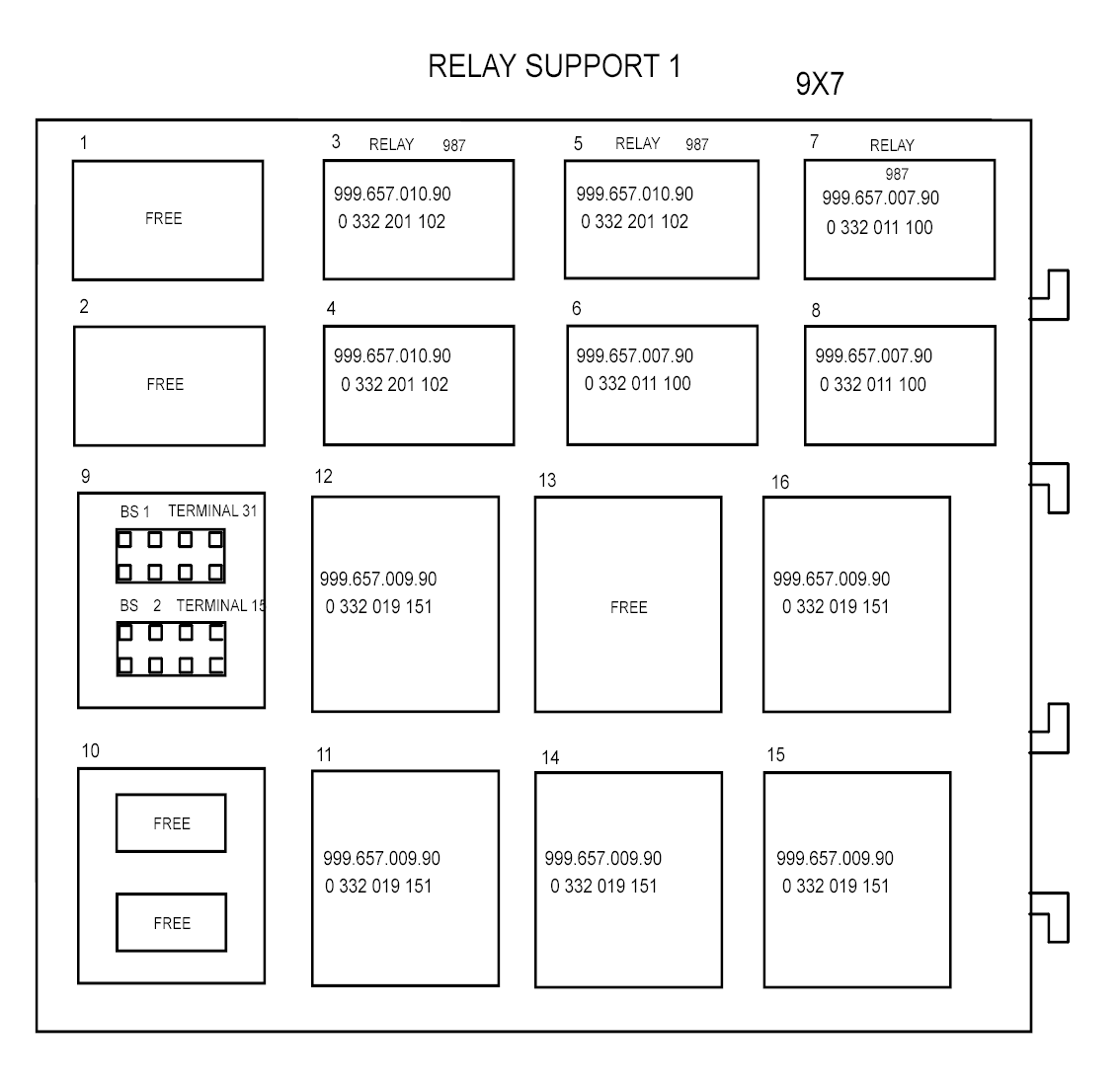
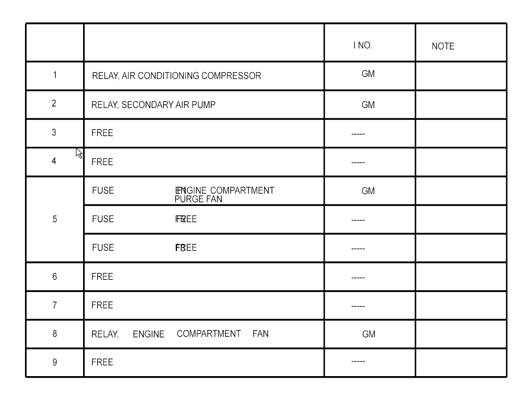
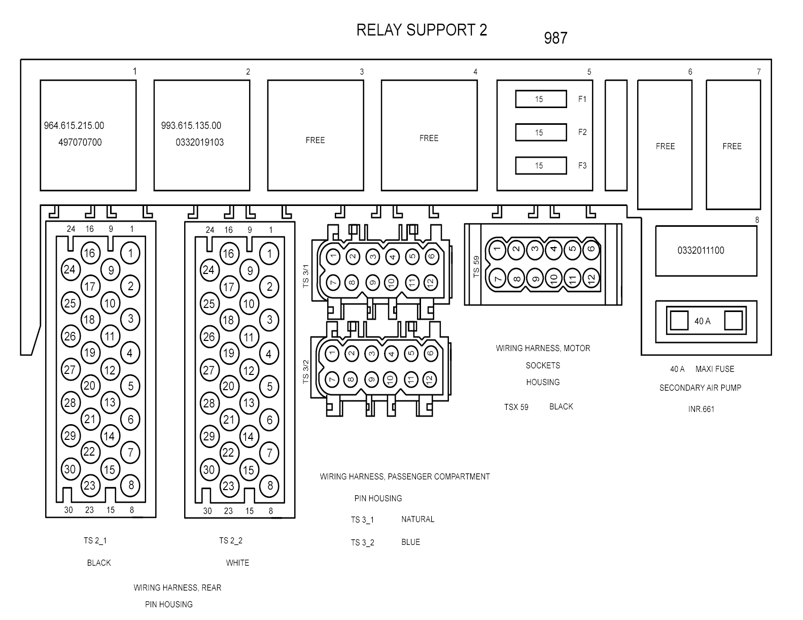
My first post on this site. I have been searching on several forums trying to find the location and access for the relays. I've been able to find the location and am just starting to dig into how to access them. To find out which relay panel I really need to get at I'd like to know which relays are in the panels. Found one panel up under the dash (drivers side) which looks like it will be the most difficult to get at (maybe need to remove the lower dash panel to access that one). The other appears to be in the rear behind the carpet on right side of trunk. Any help here would be appreciated. Thanks,1 point
-
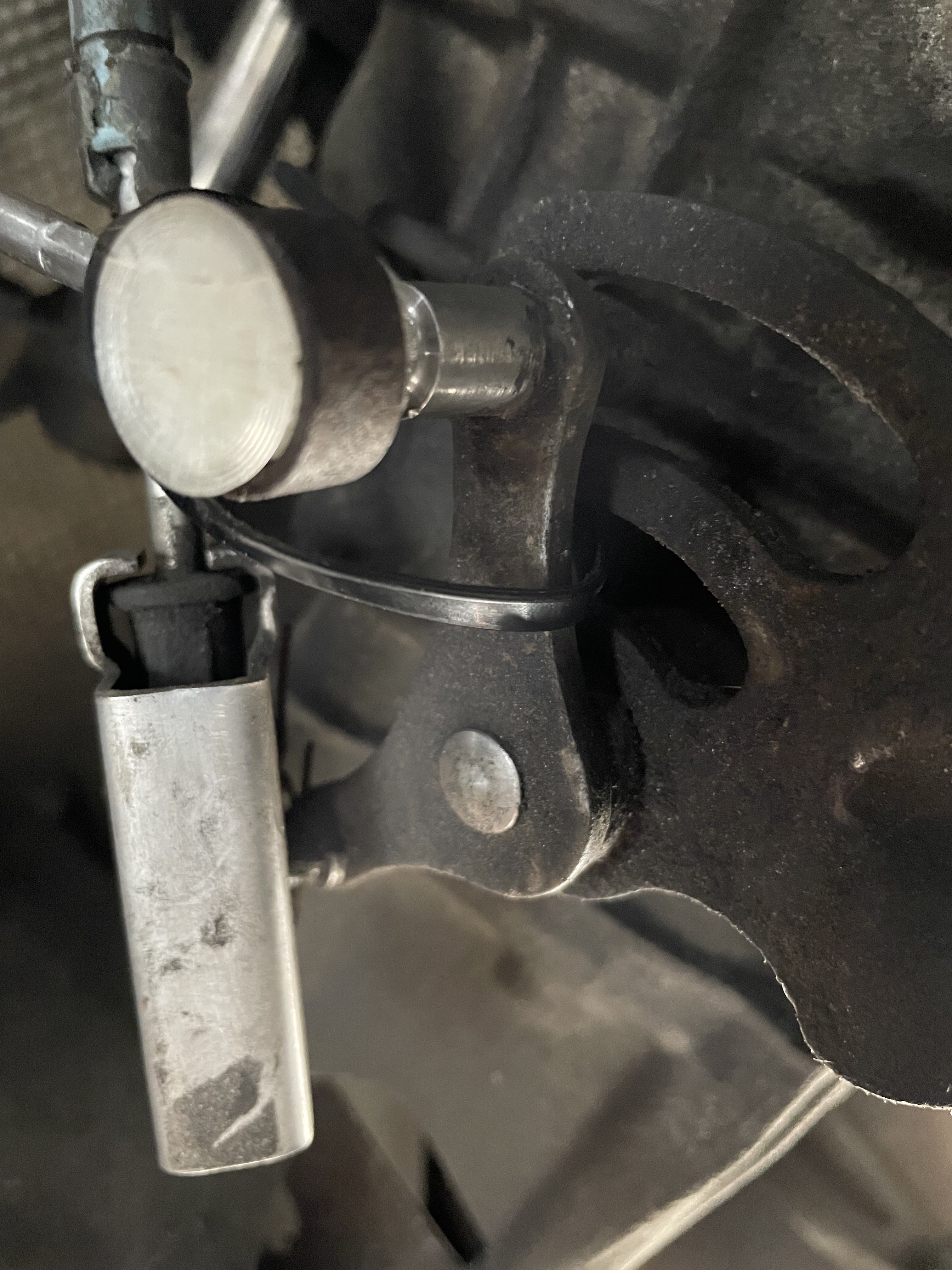
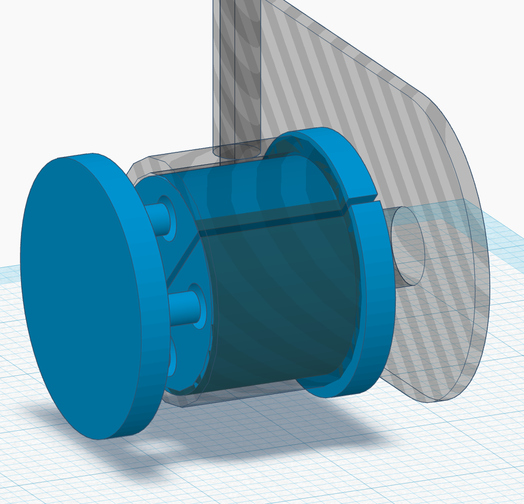
This is what it looks like right now. First extended drive completed without any issue. Slightly more precise shifter feel (duh.. less slop) 🙂 . .
1 point
-
1 point
-
Recently ran into this issue as my mirror fell off. (Thankfully it didn't break.) For those to whom this happens, the method above will not quite work. If your mirror falls off (with the base attached), clean the residual glue off and identify the metal circular base, which extends about a .25 to .125 from the base. For tools, I used a crescent (vice) wrench like the one above pictured. I also used channel locks, a microfiber towel, and (importantly) gloves. Last thing you want is the tool to shear off and bang your hand up. Attach the crescent wrench to the metal base. Wrap the microfiber towel around the mirror base housing and get the channel locks affixed. Twist the metal base COUNTERCLOCKWISE 90*. This will unlock the metal base from the mirror base housing. Acquire some glue (I used the 3M high bond adhesive), clean the working surfaces and reattach. Done.1 point
-
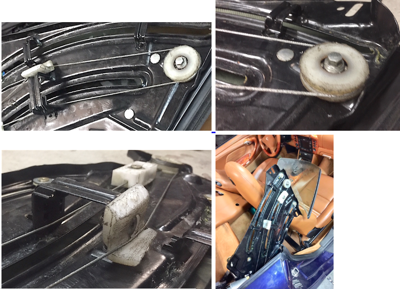
The RHS rear window regulator on my 02 C4 Cab broke last week too. Above posts were helpful to get this thing out and in quickly. My remaining problem was that I had that quick replacement for the broken regulator was not as simple as I thought (not much supply on intact used items, and rebuilds will take at least a few days back & forth). Short on patience, I analyzed the technical problem itself it turned out that the upper roll and rear string guide were compromised ((cracked in two pieces and missing at all resp.)). I ended up making a custom roller and guide from some old in-line skate-type rollers (yes, including one ball bearing) and another Polyamid block for the guide. The rest was some filing / cutting (I had a lathe to cut the string grove , but otherwise I used hand tools), and after about two hours later, I had the roll-arch-drive back to life assembled. The drive runs very good, and I think the bearing is a real upgrade to the drive, and possibly will outlast many other bits on the car. Since it was really no big deal to get this fixed much quicker that ordering anything- here a few pictures for those who may consider a DIY - fix of the drive parts as well. iH
1 point
-
Those struggling with that lower nut- there is a rubber plug which when pulled provides access to the nut.1 point
-
Oh man, I hope you have a better result than I did with my 09 2S. Mine failed when I tried to pull away from a traffic light a year ago. Got the transmission emergency run on the dash. Car wouldn't move forward or backward. The gear indicator flashed back and forth between 1 and 2 when I had it in drive but the car wouldn't move. Couldn't clear it with Durametric while at the traffic light. Shift rod 3 failure. Towed the next day to a PIWIS which cleared some of the codes but could not clear the Shift rod 3 error. Tech tried first to run PIWIS calibration routine and then to reflash it - both to no avail. I was out of warranty and ended up paying for PCNA re-manufactured unit to be installed. Based on other failures he had seen, tech thought the issue was in the hydraulic section of the box but of course Porsche doesn't share what they found when the failed unit was opened up in Germany. What part of the country are you from?1 point
-
P0455 Leakage in fuel tank system Diagnostic conditions D Vehicle speed = 0 km/h D Engine speed = 0 rpm D Correction factor, height > 0.73 D Coolant temperature upon starting the engine may be no more than 6.8 K above ambient temperature D Coolant temperature when engine starts > 3.8 °C D Period for which the engine needs to have been running before ignition is switched off > 20 minutes D Ignition has been switched off for at least 10 seconds. D Ambient temperature 4 … 35.3 °C D Active charcoal filter load < 3 for minor leak D Fuel tank fuel level 10 … 54 litres D Battery positive voltage 11.02 ... 14.5 V D No fuel tank filling D No faults detected for ambient pressure sensor, coolant temperature sensor, vehicle speed sensor D No output stage faults detected for DMTL pump motor, DMTL switch-over valves and tank vent D No fault detected for tank vent (flow) E The diagnostic conditions can also be established using the PIWIS Tester via the short test "tank leakage test". After the test has begun, the ignition must be switched off. F NOTE E In this context, please also observe the function description. Possible fault causes E Tank cap not closed correctly, leaking or missing E Purge air line leaking E Tank vent leaking E DMTL (Tank Leakage Diagnostics Module) leaking E Leakage in fuel tank system Page 140 of 398 07/20/2006 Function description Tank leakage test/DMTL – Tank Leakage Diagnostics Module F Note E The tank leakage test is performed only on USA vehicles. Construction of the tank leakage diagnostics module: The diagnostics module consists of an electric motor with a small air pump, switch-over valves and a reference nozzle. In addition, the modul is heated so as to prevent the forming of condensation and ice. Procedure of the function: E The pump is operated via an electric motor and conveys air through the reference leak. The power consumed during this process is determined. E The switch-over valve switches and the air current is now directed into the fuel tank. The power consumed during this process is also determined. After a waiting period dependent on the fuel tank fuel level, it must be at least as high as the power consumption was during the reference leak test if the tank system is leak-free. E The system is identified to by leaking if the power consumption is lower during the actual leakage test as it was during the reference leak test. E An evaluation of the power consumption levels when the pump is started and after the switch-over valve has switched serves to identify faults within the tank leakage diagnostic module (e.g. pump blocked, motor spins at idle speed, valve does not switch etc.). E The diagnosis of heating, motor and switch-over valve is performed via the output stage of the DME control module. P0456 Leakage in fuel tank system Diagnostic conditions D Vehicle speed = 0 km/h D Engine speed = 0 rpm D Correction factor, height > 0.73 D Coolant temperature upon starting the engine may be no more than 6.8 K above ambient temperature D Coolant temperature when engine starts > 3.8 °C D Period for which the engine needs to have been running before ignition is switched off > 20 minutes D Ignition has been switched off for at least 10 seconds. D Ambient temperature 4 … 35.3 °C D Active charcoal filter load < 3 for minor leak D Fuel tank fuel level 10 … 54 litres D Battery positive voltage 11.02 ... 14.5 V D No fuel tank filling D No faults detected for ambient pressure sensor, coolant temperature sensor, vehicle speed sensor D No output stage faults detected for DMTL pump motor, DMTL switch-over valves and tank vent D No fault detected for tank vent (flow) E The diagnostic conditions can also be established using the PIWIS Tester via the short test "tank leakage test". After the test has begun, the ignition must be switched off. F NOTE E In this context, please also observe the function description. Possible fault causes E Tank cap not closed correctly, leaking or missing E Purge air line leaking E Tank vent leaking E DMTL (Tank Leakage Diagnostics Module) leaking E Leakage in fuel tank system Function description Tank leakage test/DMTL – Tank Leakage Diagnostics Module F Note E The tank leakage test is performed only on USA vehicles. Construction of the tank leakage diagnostics module: The diagnostics module consists of an electric motor with a small air pump, switch-over valves and a reference nozzle. In addition, the modul is heated so as to prevent the forming of condensation and ice. Procedure of the function: E The pump is operated via an electric motor and conveys air through the reference leak. The power consumed during this process is determined. E The switch-over valve switches and the air current is now directed into the fuel tank. The power consumed during this process is also determined. After a waiting period dependent on the fuel tank fuel level, it must be at least as high as the power consumption was during the reference leak test if the tank system is leak-free. E The system is identified to by leaking if the power consumption is lower during the actual leakage test as it was during the reference leak test. E An evaluation of the power consumption levels when the pump is started and after the switch-over valve has switched serves to identify faults within the tank leakage diagnostic module (e.g. pump blocked, motor spins at idle speed, valve does not switch etc.). E The diagnosis of heating, motor and switch-over valve is performed via the output stage of the DME control module.1 point
-
Hi All, I'm new here, but found this thread very helpful. I thought I would sign-up and share my experience. My 2009 Cayenne V6 (left hand drive) has been blowing cold air on the driver side and warm air on the passenger side for the past 2 years. All passenger side vents (center right, far right near the door, and rear center right) would blow the same warm air not matter what. With summer coming up, I thought I better revisit this issue. After reading a bunch of forums on this issue, I came to the conclusion that - 1) I have the 2 zone A/C system (meaning I have less flap motors than the 4 zone) 2) it seemed to me that the front, right mixing flap was the issue. I began by taking off the lower passenger panel - its 1 screw and the glove box and a piece of triangular trim on the passenger side of the centre console (it just pops off). Once those were off, I could see 2 flap motors. One was right where the lower panel was and easily accessible - it was attached to a white plastic arm that it moved back and forth. I turned the car on and played with all the A/C setting and could see that that motor was working - it moved the white plastic arm back and forth.... (note, when I turned on the car, there were a bunch of dash warnings including low oil pressure - they went away once everything was back together) The other motor I could see was not as accessible. It was more towards the center and higher up. It was to the right side of the nav screen, inside the dash... I could only assume that had to be the front, right mixing flap. I decided to take a shot and changing it. I ordered: 1) 7L0-907-511-AL front, right mixing flap (10) - from Volkswagen. This is the equivalent Touareg part. 2) this ratcheting screwdriver tool: http://www.amazon.com/03044A-4-Drive-Mini-size-Ratcheting-Screwdriver/dp/B000XYOUS6/ref=sr_1_1?ie=UTF8&qid=1464195744&sr=8-1&keywords=Neiko+03044A+1%2F4-Drive+Mini-Size The flap motor only has 3 screws.. they were tough to get out. It took me about 1-1.5 hours to unscrew those 3 screws... most of the time was spent finding the right position to unscrew the screws.... and there was not a lot of room to turn the ratcheting screwdriver (a regular screwdriver would 100% not work). So once I would get the torx bit to connect with the screw..I had to unscrew very slow (shallow turns) and often drop the screwdriver. Annoying... and frustrating.. but keep at it. Getting the new motor back in was a bit easier and I had figured out the best position to deal with each of the 3 screws. Make sure the motor connect properly to the white piece that it controls. putting the new motor in was probably about 30min max. I put back the trim piece, glove box and lower panel and turned one the car... and cold air was blowing out of all vents! Glad that is dealt with!.. I almost have no problems with my Cayenne now... I suspect the rear hatch struts are due to fail next!1 point
-
I think this will do it. Good luck. DC Porsche 997 PCM Removal.pdf1 point
-
Dave, As Silver said, it should not be too difficult to track down the problem(s). All you need is a $15 multimeter. Run your engine till warm and the low voltage shows up, then let it idle and turn on the a/c and the low beam. The current draw from the alternator should now be ~50A. You can then do the following tests. I drew a diagram with the corresponding parts. Test #1: check voltage drop between point "C" (alternator casing) and "B-" (call that V(C, B-)). Note "B+' and "B-" are the actual battery terminals, not the cable connectors on the terminals. This test shows total voltage lost between the alternator and the battery on the ground side. Expect 0.2v or less. If your ground strap is bad, it will show up in this test. Test #2: check V(A, B+) where "A" = alternator output at the back of the alternator that you can't see (use an inspection mirror) and expect ~0.5v or less. "A" is hard to get to. I fabricated a J-shape hook using a stiff insulated wire and just literally probe it blindly from behind. Wear protective goggles here since you will be close to the drive belt, a hot engine, and the always LIVE "A". This test shows total voltage lost between the alternator and the battery on the power side. Test #3: check V(A, J) and expect ~0.2v. This tests #21, which is the infamous cable that can corrode and Porsche has also revised it. Test #4: check V(J, B+) and expect ~0.3v or less. Test #5: check V(A, C), your alternator output and expect 13.5v or higher. Your problem is gonna show up in one of the tests above.1 point
-
Well... I replaced the hinge on the center console today. After reading all that was available, I went with doing it without removing a lot of stuff like the TSB. All done sitting in the back. Not hard to do. You will have to take a hack saw blade and cut off the unbroken hinge collar, then file both spots till they are flat. The U shaped rivet supports take a needle nose plier to put in place. Knock the shaft out from right to left. Vacuum the aluminum curlies out after you do the drilling.1 point
-
BTW fixed a similar "rise" in my rear seat area recently. Drop the back seats and remove the two phillips screws. I bet the tab on the rear cover under the carpet area has broken off. That causes the rear piece to flex up. I removed all the screws from the piece and took it out. Used e6000 glue and glued a washer to the broken plastic (and remaining piece I found). Allowed the back to be bolted in nice and flush.1 point
-
1 point
-
@ RFM - Is it possible to overpressurise the bellows as described by 4CN Air? Does the air suspension system have a high pressure cutout? What is the normal operating pressure inside the strut bellows? @ 4CN Air - When your air strut blew, did the other 3 struts or the opposing strut deflate as well, or was it just the blown strut that drooped?1 point
-
1) Heat is not bad. If your car were actually running at 185 you would be perfect. If you were running at 160, that would be bad. The motors are designed to operate at peak efficiency of about 180ish. 2) By "Government", do you mean this and the 11 other states with strict state standards? Or the federal government with weaker standards? They're both irrelevant. All the motors in this country and I believe the world, run at the same temp as your motor. 3) The theory is that Porsche actually thinks they have to run these motors at 210 to pass emissions. So you don't freak out, they jigger the gauge to read a false 180ish when it's actually 210. 180 is good. 210 is to hot and shortens the life of the motor. Little do they know, so the "160" theory goes and as I understand it, they could actually run them at a true and safe 180 (with a 160 thermostat), add years to the life of the motor and, still pass emissions. And so by extrapolation, after some 20 years developing this motor, they haven't figured that out yet. So the theory goes. Regards, PK1 point
-
Hi, yes Mobil 1 5w-50 is the only SAE50 viscosity lubricant Approved by Porsche. It is an excellent lubricant with a long history. It ia available in most Countries except the USA Mixing most Mobil 1 products to achieve a "supplementary" viscosity can be done without the risk of loosing the benefits of the overall base fluid/additive package There are two exceptions to this however. M1 0w-40 and M1 Turbo Diesel Truck 5w-40 (non Approved) should not be mixed with other Mobil 1 lubricants if you wish to retain their unique and quite sophisticated formulation I use the "parent" of M1 TDT 5w-40 - it is a Commercial lubricant called Delvac 1 5w-40 Regards Doug1 point
-
My 2001 996 had the hardtop on it (with the improved hardtop latches, per Porsche). When I went to remove it last night, I had a very hard time getting the top off. I opened the doors, lowered the rear quarter windows, fully unlatched the front catch, and then opened the latches in back (yes, all the way to the stop). It was a real struggle to get the back to release; with the latches open I had maybe a quarter or half inch of vertical play, but could not lift the top any higher in back than that. After 20 minutes of opening and closing the latches I finally popped the front out of the tabs and then muscled the back out. Did I do something wrong (like not lowering the front windows even though the doors were open), do I need to adjust the latches, or do I just need to apply more force?1 point


.jpg.dc738c9c4b596fb32dc8804f1d09ef17.jpg)
.jpg.2b81d572e107c855fcc8db3e25692ab0.jpg)
.jpg.24efdfb320157fc0d662df27ce09666f.jpg)
.jpg.5627410ee3b5654a00328f510510ffc0.jpg)
.jpg.28f08e8939116d70c2c8ac4733a62c82.jpg)
.jpg.276acbb530288b0b17cefec5ad944f23.jpg)
.jpg.e033379ecc7fcc3670ce0fa975ffbb59.jpg)
.jpg.2a8548c3ef4c34732f5f055bcb179355.jpg)
.jpg.96d241cf03b2076b1dd034ff7dfcab8a.jpg)
.jpg.80dc5a049e16cfce4249e767e003ee29.jpg)