Welcome to RennTech.org Community, Guest
There are many great features available to you once you register at RennTech.org
You are free to view posts here, but you must log in to reply to existing posts, or to start your own new topic. Like most online communities, there are costs involved to maintain a site like this - so we encourage our members to subscribe or donate. All subscriptions and donations go to the costs operating and maintaining this site. We prefer that guests take part in our community and we offer a lot in return to those willing to join our corner of the Porsche world. This site is 99 percent member supported (less than 1 percent comes from advertising) - so please consider an annual subscription or donation to keep this site running.
Here are some of the features available - once you subscribe RennTech.org
- View Classified Ads
- DIY Tutorials
- Porsche TSB Listings (limited)
- VIN Decoder
- Special Offers
- Paint Codes
- Registry
- Videos System
- View Reviews
- and get rid of this welcome message
It takes just a few minutes to register, and it's quality Porsche information at a low cost.
Contributing Members also get these additional benefits:
(you become a Contributing Member by subscribing or donating money to the operation of this site)
- No ads - advertisements are removed
- Access the Contributors Only Forum
- Contributing Members Only Downloads
- Send attachments with PMs
- All image/file storage limits are substantially increased for all Contributing Members
- Option Codes Lookup
- VIN Option Lookups (limited)
Leaderboard
-0001-0001.thumb.png.17f5bb25bf8ec261a17c21e6321c8492.png)


Popular Content
Showing content with the highest reputation since 06/07/2025 in all areas
-
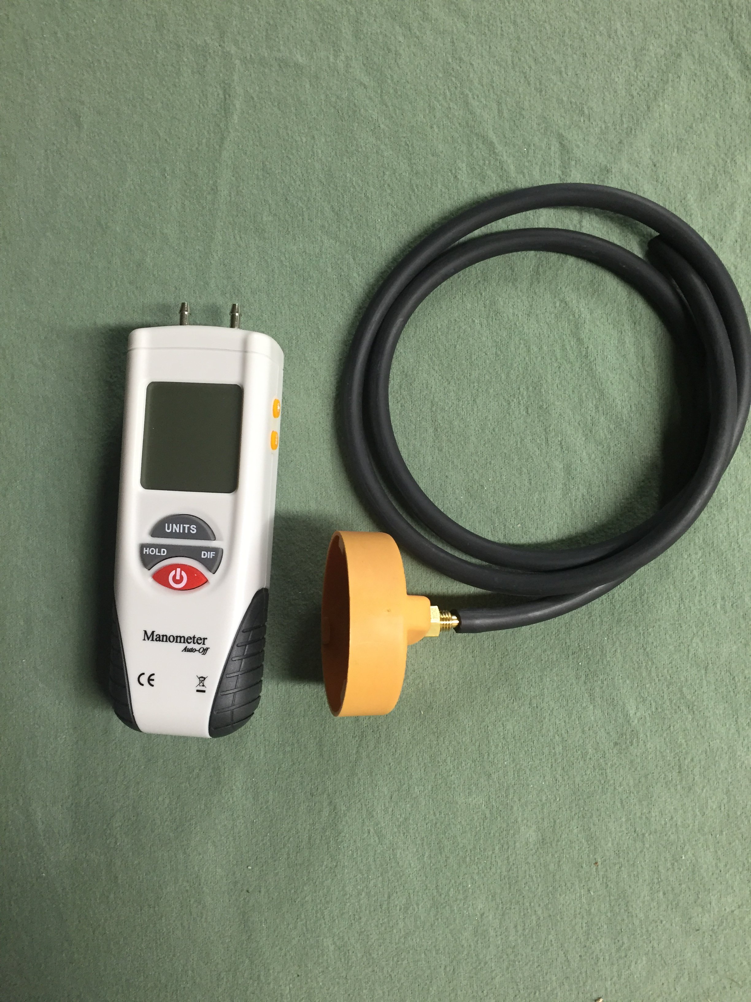
If the oil cap is hard to remove, you have a high vacuum level in the sump, which is bad for a variety of reasons, including lean stalling. The correct way to access the AOS is to fully warm up the engine by driving the car for 10-15 min, then replace the oil cap with the one in the picture above with a hose that connects to the digital manometer. If the vacuum level exceeds 6-7 inches of water vacuum, the AOS is leaking air into the intake system, causing the lean stall conditions. The normal level of vacuum is typically 4-5 inches of water, which is a really weak vacuum level, so it doesn't take much of a leak to cause problems, which is why we always checked every car that passed thru the shop with the manometer.3 points
-
The AOS can either be pin pointed or eliminated by having the car's sump vacuum level checked with a digital manometer (most quality shops have them as the AOS is a perpetual issue; surprise the dealer didn't do this).
 2 points
 -
Welcome to RennTech If you do not have access to a wiring diagram for the vehicle, probably the easiest way to check the ground is to pull the bulb in the light and use a multimeter to check the condition of the ground at the bulb socket.2 points
-
We have used them here in the US for years at MUCH colder temperature's than you get without ANY issues. Put on the adaptor, add external magnets such as the Filter Mag, and enjoy both better filtration and peace of mind.......2 points
-
Welcome to RennTech The factory radio had a ground wire that had to be attached to the car's chassis under the dash as a simple anti theft device. If that ground is not there, the immobilizer will prevent the car from starting.2 points
-
Many times the servo is not bad but the foam from the flaps has deteriorated and jammed their movement. I would check that first then rest the codes and test before actually replacing any servos.
1 point
-
2006 CAYENNE 955 4.5 V8 DRIVER SIDE PRIMARY CAT REPLACEMENT Full size pictures can be found HERE Writing this down hoping it can help out another pepper owner. SKip to the bottom if you want the short version. Had to replace the drivers side (LHD) primary catalytic converter as the flex pipe had completely corroded away and was flopping loose in the wind. I got lucky and found an aftermarket one on eBay for significantly less than what the dealer would charge me. You’ll need an assortment of tools for the job: Jack Jack stands Ramps for rear 10mm sockets 12mm sockets 13mm sockets Numerous extensions Wrenches in above sizes and flex head ratcheting are awesome 22mm O2 sensor wrench or crowfoot Straight ⅜” and ¼” ratchets and breaker bars for extra leverage as needed. Flex head ⅜” ratchet Long flathead screwdriver to open up the clip holding the O2 sensor wire T25 screwdriver or bit for your screwgun for trim pieces #2 screwdriver or bit for your screwgun for trim pieces Total actual work time was about 8 hours. I could have done it in about 5 or even less if I was truly ambitious, but was taking my time and making sure I didn’t break anything in the tight space. The time also included jacking up the car, removing the underneath skid panels, engine compartment plastics, drivers tire and wheel well liner as well as reinstalling them. See Pelican Parts for the skinny on accomplishing all of those tasks. I’ll skip those tasks here. https://www.pelicanparts.com/techarticles/Porsche_Cayenne_Tech.htm Also crack open the rear hatch and block it from locking as you’ll want to disconnect the battery ground. Here is a video that shows how. Super easy and never knew myself. No need to flip the seat. How to disconnect battery ground in Porsche Cayenne (955) I will preface my replacement with the added bonus of the car having the secondary CAT delete already done. So no fighting with those. So under the car, first things first was loosening up the connection between the tailpipe section and the straight pipe, which was connected to the primary CAT. As the existing bolts on the CAT were rusted and frozen, I just snapped them off knowing they would be replaced anyways. Don’t waste your time on PB Blaster or heat. Just break them off and be done with it. So with the easy work complete now it’s time to dive into the fun part. Move up under the car so you’re looking straight up where the CAT meets the exhaust manifold. You’ve got 3 bolts above you that you’re wondering how you’ll ever get to them without taking out the front O2 sensor and even then how. Give them a spray of PB Blaster or your choice of penetrant. Now move to the front of the car in front of the sway bar, there is an opening where you can see the 3 nuts on the exhaust manifold. With a combination of extensions you can reach the nuts with a 12mm socket. You can let them soak for a little while as you have another cup of coffee or beverage of choice. At this point you may be wondering why I haven’t mentioned the O2 sensor on the top of the CAT pipe. Well, because I drove myself crazy trying to figure out how to get it out. I went after it 8 ways to Sunday. From the top with swivels and extensions and the same from underneath. I could barely get a finger over it and did manage to get the socket on it but then couldn’t get it broken free as the leverage just wasn’t there, or the socket/crowfoot slipped off. Needless to say, I wasted about an hour or so on this and questioned my seemingly foolish decision to approach this project. In the process of doing all of this, I figured out I needed to remove the middle skid plate support bracket for more room to reach up in the small area. Working by myself created new opportunities to be resourceful, or stupid depending on point of view. Since I was already committed to this endeavour by already removing, AKA breaking, the lower sections of exhaust piping, **** the torpedoes and full steam ahead. I ended up just unbolting the CAT from the exhaust manifold, dropping it down and slightly rotating it. At that point I had a good view of the O2 sensor and slipped the O2 sensor socket right over it with a breaker bar attachment. With the room to get leverage and a straight shot at it, it came loose with a marginal amount of effort. Unscrewed the sensor by hand and pushed it behind the steering column. Now for the next problem. The CAT was just big enough to not slide out with the heat shield of the steering column shaft in place. So, prop the CAT in place and remove the heat shield (2-10mm bolts), giving that extra ¾ of an inch. And so with a small amount of finagling, out she came. Could I have worked a little more on it and fought it out? Maybe. But for two 10mm bolts, easy choice. At this point in time, I called it for the day as I was now about 5 hours into the whole job. Sunday morning - here we go for part 2. Now knowing how it came out, it should make it easy to go back in. And yes, it was. Reverse the process of the removal. Slide the new slimmer CAT up into the general position it needs to be, let it rest on the other parts while the O2 sensor is installed. I did unclip the connector up in the engine bay and hang it from the hood so it would spin freely while installing it. A tip I saw elsewhere, thank you. Now push the CAT up into position and viola!. NO! WAIT! The mounting bracket is farther forward than on a stock CAT by about a ½ inch and slightly rotated off the axis of alignment from the engine bracket. The CAT won’t go all the way forward to mate with the exhaust manifold. So… Now it’s pushing, rotating and mild cursing to get it around the engine bracket. In the end, I got it together. Final decision on the bracket, it’s staying unbolted. Not the preferred method, but that’s how we’re rolling since I don't have a welder anymore to move the bracket on the CAT. At this point I was able to get my hand up to get the nuts on the ends of the bolts and finger tight them. Slide around to the front with the long extension and reach in to tighten them up. Now, if you’re lucky, you may have an air ratchet or a battery operated ratchet, which I did, to tighten them up. Do so at this point. Back to the middle of the car to reinstall the short pipe piece to the flex end of the CAT and to the tailpipe. Reinstall the middle skid plate support bracket and you’re just about complete. I hope for all of you who lasted this far have good luck getting around the secondaries if you still have them or figure an alternate plan for that. Time to start the car before I put everything back on and drop it to the ground. Hook up the battery (sparky, sparky), key in the ignition, hand pushing the brake AND… nothing. PANIC!!! I know there’s power. The interior lights come on, chime is going ding-ding. Again.. Nothing. Hold on, let’s breathe a second. Oh lord, the wife will kill me if I killed her car. 3rd time, small prayer to Stuttgart and… SHE LIVES AND BREATHES!!! And much quieter too. Do a couple of start-stop operations to double check it’s all working and then off to reinstall all the plastics and drop her to the ground. I will say, fighting to get the wheel liner on, is an extraordinary test of patience and will power. I think I fought that alone for over 30 minutes. If anyone has tips for that process, I’d be eternally grateful. Couple of side comments on this. The CAT I purchased was an aftermarket unit I got off of eBay and have no idea who manufactured it. There were no studs in the flanges, just 3 bolts and nuts per flange. I was worried they were going to fall out during the install, but the new gaskets held them in place as the holes were the right size to screw the bolts through them by hand. I know this helped during the reinstall and not having to bend or cut off the bracket on the CAT. For the heat shield, some places had said to unbolt the steering shaft and move out of the way entirely. I did not want that headache to do a realignment of the shaft/steering wheel. So I just did the minimum I thought would work. Now that you’ve gotten to the end of my story, I hope it will give someone else the courage to take on the project. Take your time, step back, breathe from time to time and don’t rush it. It will happen. Please make sure to tip your waitress. SHORT VERSION Put car on jackstands or at least front end Put rear of car on ramps if only jackstands in front Disconnect battery Remove front left tire Remove wheel well liner Remove underbody skidplates/plastics up to bumper Remove heat shield from steering shaft Remove middle skidplate support bracket Unbolt/snap off bolts from primary CAT flex pipe to tailpipe/secondary CAT Remove short tailpipe section if secondary delete performed From front of car, reach in and unbolt the 3 nuts holding primary CAT to exhaust manifold Drop CAT down and rest it on car Using O2 sensor socket, reach up into area and remove sensor Pull CAT out of car Push new CAT up into the void and rest on car Install O2 sensor Push CAT up to exhaust manifold and bolt together Install engine support bracket (if applicable) Install tailpipe section to flex pipe end of CAT Install skidplate support bracket Install skidplates Install wheel well liner Install tire Lower car to ground Install engine compartment plastics Reconnect battery Start car CELEBRATE Now if someone can share an easy way to do the passenger side......
1 point
-
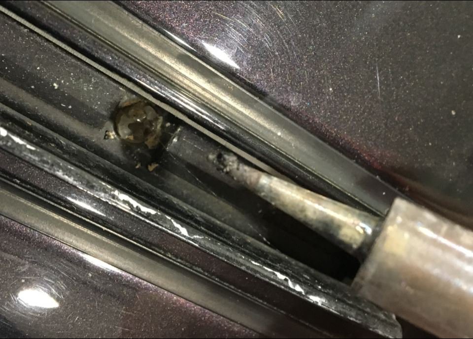
It that a plug or plastic pop rivet? I am only finding the plastic rivet.1 point
-
Remember the new ride height will be 10 mm lower than the stock height - plus the springs, struts and swaybars will all be firmer than the stock items. As I said before another option PSS-9 (adjustable) Coilovers - likely easier to find as either OEM or aftermarket.1 point
-
Having spent months chasing down my very heavy steering (yes I know some like it like that) I have finally managed to over come the heavy steering by bypassing the servotronic system and locking it into 75% assistance effort. Here's how I did it, but I would appreciate any thoughts on why it wasn't working if anyone has any constructive comment about the acceleration sensor readings - which is what I think the main culprit is.1 point
-
Chances are your 20 plus year springs have softened and are already sagging a bit. Springs, swaybars and struts are a matched set - I would not mix them as you could produce unstable handling. Especially if you track the car. RoW 030 is fine for street and most track driving - you just have to be careful of large speed bumps on the street. PSS-9 (adjustable) Coilovers can supply suspension tuning and even lower for track days - but you would definitely want to raise it up for street.1 point
-
I waited until I could confirm my problem is solved. After asking the dealer multiple time about vacuum level measured with a digital manometer and never getting a straight answer, I spent some time talking to the tech before proceeding. According to him, the reason the car would start when cold is it was still going through the 90ish second startup sequence with secondary air injection, coupled with the vacuum leak caused by the AOS. Which, to my not-very-Porsche-tech brain kind of made sense. After getting the AOS replaced, along with a cracked brittle oil fill tube and one or two other related minor bits that were also old, cracked and or worn out, the car seems to run fine, was actually quieter than I ever remember, and the stalling problem is resolved. And no CEL since the repair. There was never any big clouds of smoke usually associated with a failing / failed AOS.1 point
-
Try 97861 point
-
Try 89641 point
-
Non, push down with one hand, squeeze the ribbed bottom ring with the other hand and pull up, this is not as easy as it looks, succes.1 point
-
I'd start with checking the alternator, is it putting out 14.5 V DC at idle? If not, I would check to make sure you properly reconnected the wiring.1 point
-
What are your voltages? Resting, idling, driving above 2000rpm? There are gizmos to help with this monitoring - Antigravity Batteries has a battery tracker. Others plug into the cigarette lighter. Do you have any codes (can be read with Durametric and other (OBDII) readers)? I've read stories on Rennlist about induced electrical noise in the sound system even when the sound system is not turned on. Might your alternator be damaged or no longer have a high quality ground? Could the noise be mechanical (transmitted noise)? You did change pulleys. Run the car a few minutes without the serpentine belt and see if the noise is reproduced.1 point
-
Do this someplace safe... Put in Neutral and see if the noise continues or not. If it does not continue then it is likely in the drivetrain (transmission, transfer case, driveshaft, rear end}. If it does continue then it is likely in the running gear (wheel bearing, axle shaft, or even warped brake discs).1 point
-
Sorry I have not replied. I did not buy the Cayenne it belongs to a friend of mine and I enjoy working on them when I have time so I spend a few days a week fixing stuff. It been fund and I love finding something that is bad from either age or the last repairman messed something up. so far I have replaced both valve cover seals with the cam actuator seals and spark plug tube seals and new spark plugs. I also replaced the vacuum pump and fixed the power brake vacuum hose that was cracked on both ends, I also replaced the purge valve. I also made a new vacuum line from the oil air separator to front timing chain cover out of copper pipe with rubber ends. I was very pleased to see how nice the motor runs now. I also replace the rear hatch actuator to unlock the rear hatch before you would hit the button but it would not unlock you had to use your finger to manually unlock it from the inside. that's fixed now. Right now I have the head liner and the sunshade off and getting ready to clean the old headliner before I put in the headliner but, before I put back the headliner I'm going to replace both struts for the rear hatch, the glass does not stay up at all and the hatch does stay up but it slams when its closing. I also fixed the drivers seat back cover that kept coming off, I ran a screws 1/4 through bottom of the back cover to hold it to the seat. I have to do the same thing to the passenger side seat too. once I have everything fixed inside the car I need to see what the oil leak it has/had is coming from it could be from old valvecover seals that I replaced or the transmission is leaking. when he first dropped off the car the oil leak was massive and now after the work I have done to the car the oil stain is a drop so that may be fixed, but I need to see and make sure. Oh I'm having a problem finding the struts for the hatch the car has the power liftgate, I find the struts for the glass but I can't find for the power lift gate, does it now use struts for the hatch on the power lift get?1 point
-
Try 84581 point
-
Try 21901 point
-
Try 54251 point
-
Here is the documentation from the Porsche DME manual P0327 210 Knock sensor 1 - below limit Diagnosis conditions • Engine speed more than 3600 rpm • Engine load greater than 45 % Possible fault cause ♦ Break in wiring or short to ground ♦ Contact corrosion on the connector ♦ Knock sensor loose ♦ Short circuit to B+ ♦ Knock sensor ♦ When a fault is stored, the ignition angle is retarded for all cylinders in the range in which knock control is active. ♦ Knock control adaptation is inactive. ♦ If knock control becomes active here, this may indicate engine damage (increased noise level) Affected terminals Terminal III/49 and III/50 Diagnosis/troubleshooting1 point
-
I came across this old post in a Google search and thought I'd provide an update. The Porsche part number for the adjustable linkage is 986-424-931-06 and is available from Pelican Parts for about $250. Numeric Racing makes an all-metal version for $130. The adjustment procedure for the adjustable-length linkage is available in the Porsche OEM Service Manual.1 point
-
If you get a honk it means you have at least one zone open or one (or more) fault codes. You will need a Porsche compatible scanner to get the fault code and report it here. It should narrow down exactly where the problem(s) are.1 point
-
Because it is a 2005 engine, it would most likely have the oversized third generation IMS bearing in it, which means it cannot be removed without total disassembly of the engine because it will not fit through the opening in the engine cases. One way to know for sure would be to pull the trans, clutch and flywheel off and look at the nut on the IMS bearing center bolt; if it is 22 MM, you have the oversized bearing, which was the only one to use that large a nut.1 point
-
The engine serial number would have been built in late 2005 or early 2006. Porsche rebuilt engines always get the latest parts and a warranty. To be sure you would have to open the engine to get the IMD diameter. If you want insurance then you can install one of the 3rd party IMS oiler solutions. IMS Solution: Oil Fed Plain IMS Bearing - No Ball or Roller Intermediate Shaft Bearings LNENGINEERING.COM IMS bearing failures are expensive. The IMS Solution is the only permanent solution to the IMS problem. Proven protection and the industry’s best warranty.1 point
-
Found the solution, the circuit board inside to control unit was corroded at the power input, cleaned resoldered and now working! That’s saved a fair few pounds, just all the trim to put back1 point
-
I'm heading to the track for the first time and Shenandoah circuit at Summit Point apparently has a little crest where some people catch air. I don't want the rollover bars to scare the crap out of me while on the track. Any ideas?1 point
-
P0441 code is EVAP purge valve, alongside the drive side intake manifold tubes. P2281 Code is most likely an air leak between the MAF and the throttle body, the code generally means that the powertrain control module (PCM) has detected a degree of airflow at the mass airflow (MAF) sensor which does not exist at the throttle body.1 point
-
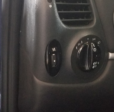 Rotary Switch to Manually Turn on the Cooling Fans Porsche 996/986 So the rotary switch has a fan symbol that lights up the same colour as the rest of the buttons in the car when the headlights are turned on. To turn on the low speed fans, rotate the dial up and the symbol lights up blue. Turn it down for the high speed (and the engine fan as well) and it turns red. The automatic function of the fans is not affected by this at all. In fact, the indicator lights will turn on when the car switches the fans on, so you can tell when the high or low speeds are on, which is cool. So the function of the rotary switch will be: -when at rest and headlights/parking lights are not on, fans are not on and the indicator light is not on. -when the dial is turned up, low speed fans are on and the indicator light illuminates blue. -when the dial is turned down, the high speed fans are on along with the engine bay fan and the indicator light illuminates red. -when the headlights/parking lights are on, the indicator lights orange. We will need 1 RGB LED, 1 diode, 1 resistor of 500 ohms, 1 resistor of 1000 ohms, 1 resistor of 5000 ohm (this may be different depending on the LED you use) Here is the wiring diagram that we will follow to make this work. First you need the headlight level switch. It was available only on the 996.1 cars and is part number: 996 613 230 01 You need to disassemble it, as all the circuitry inside will be replaced, and the headlight symbol removed. Remove the circuit board now, as it will be replaced with one we will make from scratch. Remove the LED as well and all wiring inside. Now you need to make a new circuit board to replace the old one. You need to visit an electronics store and get Ferric Chloride and copper clad board. Cut a piece of board to match the size of the old circuit board. Cut it roughly with a saw and then use a file to get it down to exactly the shape and size you need. Peel off the protective film and then lightly sand off the bluish film off the board until you have only copper exposed. Now you need to draw on the circuit onto the copper with a sharpie. I did it backwards, but it is soo much easier if you sand off the blue film and then draw the circuit. The chip will now go into the Ferric Chloride. The liquid will eat away all of the copper except for the parts you drew in sharpie, as the liquid does not react with it, leaving the copper underneath protected. When you take it out of the Ferric Chloride, you will have your chip. Clean off the sharpie with rubbing alcohol. Now you will drill 3 small holes in the bottom of the chip for wires to attach to. You will need to solder in bare solid wire into each of the holes. One contact will be for high speed, one for low speed and one for ground. Here you see the chip in place with the wires leading out of it. Each wire will need to be soldered onto a contact in the switch that leads to a pin. Now for the LED. You need a frosted 5mm tri colour RGB LED with a common cathode. The ground for the LED will go to pin 4 in the switch - same as the grounds for the high and low speed for the fans. The lead for the green will go to the 3rd pin. There is not enough pins for everything, so you will need to add more. I did this by putting a noche in the base of the switch to allow a couple wires to run out of the switch to another connector. I just picked up a male/female 2 pin connector from ebay like the one below. You will need resistors for these LEDs. Green is much stronger than red, so I used a 500 ohm resistor in series for the red LED, and 5000 ohm resistor in series for the green LED. 1000for the blue. You will need to test the light intensity and how the colours mix to get you the orange you need using different strengths of resistors to match the rest of your buttons. There is not much room inside the switch, so I placed my resistors and the diode outside the switch, which you can see here. Next is to make the fan symbol. Sand off the headlight symbol from the indicator piece. I had a tiny fan laser cut by a shop for me onto vinyl, which I then placed on the piece and painted black. Removed the vinyl, and now there is a perfect symbol of a fan that the LEDs will illuminate. Place back in the switch and now put it all back together. Switch is done. Now to wire everything up to the switch. The diode has to go where you see it in the diagram. It allows current only in one direction. Again, there is no room for it in the switch, so I have it in the wiring outside the switch. The diode will allow current to flow from the power supply for green LED to the red LED (this will make orange). You may need to test different resistor values to get the right colour of orange. Now to make it all work. We will need four 12v relays. I installed all 4 relays in the relay tray above the fuse box to make it look as OEM as possible. But they could go anywhere. You will need 4 relay plug with the metal connectors if you do what I did. Part number is 928 610 511 00. You need to locate the 2 low speed fan relays and the 2 high speed. The low speed relays are numbers 19 and 21, while the high speed relays are 20 and 22. Disconnect the battery in the car. First remove the fuse box panel. It is held on by 4 screws. You can then just pull it out. The relay box is above it. It is best to remove the relay box. It is held in place with a single nut, and clipped in on the opposite end. Flip the relay tray around so you have access to the back. I removed plugs that were in my way. Now use the wiring diagram from earlier to make the wiring connections you need. The proper routing and connections of the new wiring is all there in the diagram. The relays labeled as normally open or normally closed are the new relays you are adding. The purpose of these relays is to turn on and off the appropriate LED colour to indicate whether high or low is on, and to turn off the orange (if headlights are switched on) when fans are in operation. If you want the engine bay fan to also turn on with the high speed fans, then you will need to run a wire splitting off from the wire runs from pin 85 from relay 22 all the way to the back behind the rear passenger. There is another relay box there. I removed the rear quarter interior panel to help with running the wire as well as the bonnet/engine cover release panel trim. But you don’t have to, just tuck the wire in. Remove the carpet in the back to expose the relay box. It is on the right and is held in place with a nut in the centre and 2 screws on the right. You can see the wire I ran from the front. Flip it over and find relay number 8. You want to tap into pin 85 of that relay. Put it all back together. Now wire up the switch. The wire from pin 85 from relay 22 goes to pin 1 of your plug for the switch. The wire from pin 85 from relay 21 goes to pin 2. The wire from pin 87a from the normally closed low speed relay (see diagram) goes to pin 3. The wire from pin 87 from the normally open low speed relay (see diagram) goes to the connector you added to the switch - green wire The wire from pin 87 from the normally open high speed relay (see diagram) goes to the connector you added to the switch - red wire From the switch, we have a ground wire. This can go to any ground point in the dash. I found a spot close to where the switch goes and grounded it there. There is one last wire, and this is to get power to the red/green LED when the headlights are on. You can wire this to any switch in the car that illuminates. I took power for this from the intermittent wiper in the dash for power. Now with everything wired up, this should work. With the car on, but no headlights and the switch is at rest, there should be nothing. When the headlights are turned on, you should have the fan symbol light up in orange. Turn on the high speed fans, and you should have the engine fan and the 2 front fans on and the symbol should be red. On low speed, only the 2 front fans will be on at low speed and the symbol should light up in blue. The car will still turn on the fans automatically, and when it does, the fan symbol will also light up to let you know the car has turned on the fans at either high or low.1 point
 -
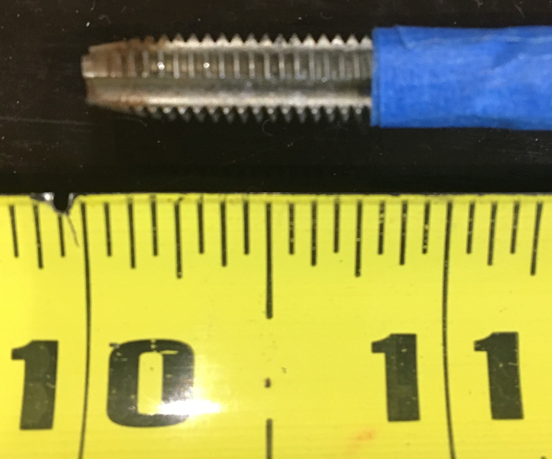
On my 2000 C4 I was lucky enough to have nylon screws. They broke of course, but drilling and tapping was easy with a few tricks and observations: Using a soldiering iron to melt a hole through the center of the nylon screw makes drilling MUCH easier Used a 3/16" drill bit to remove the majority of the nylon then used a 6mm x 1.0 to clean the threads Plunge depth is 3/4" Use a "bottom" tap rather than a "tapered" tap so you clean threads quickly and without significant insertion.
1 point
-
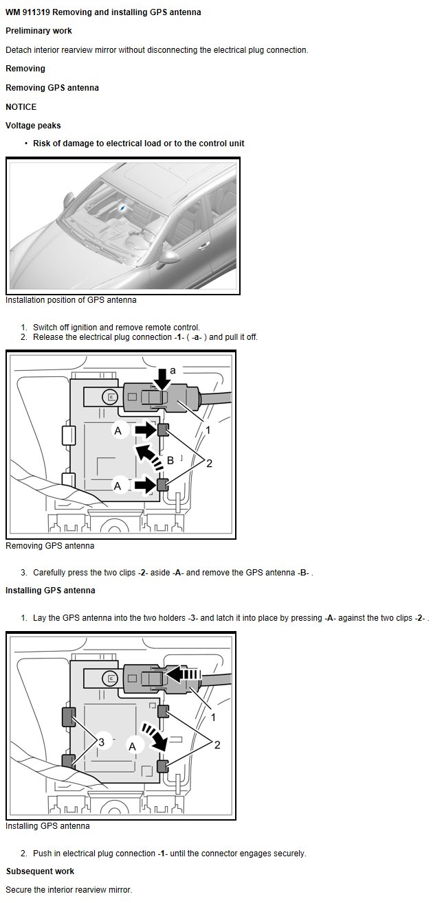
Osunick, Your GPS antenna is located behind the rearview mirror. Hope this helps.
1 point
-
1 point
-
P0455 Leakage in fuel tank system Diagnostic conditions D Vehicle speed = 0 km/h D Engine speed = 0 rpm D Correction factor, height > 0.73 D Coolant temperature upon starting the engine may be no more than 6.8 K above ambient temperature D Coolant temperature when engine starts > 3.8 °C D Period for which the engine needs to have been running before ignition is switched off > 20 minutes D Ignition has been switched off for at least 10 seconds. D Ambient temperature 4 … 35.3 °C D Active charcoal filter load < 3 for minor leak D Fuel tank fuel level 10 … 54 litres D Battery positive voltage 11.02 ... 14.5 V D No fuel tank filling D No faults detected for ambient pressure sensor, coolant temperature sensor, vehicle speed sensor D No output stage faults detected for DMTL pump motor, DMTL switch-over valves and tank vent D No fault detected for tank vent (flow) E The diagnostic conditions can also be established using the PIWIS Tester via the short test "tank leakage test". After the test has begun, the ignition must be switched off. F NOTE E In this context, please also observe the function description. Possible fault causes E Tank cap not closed correctly, leaking or missing E Purge air line leaking E Tank vent leaking E DMTL (Tank Leakage Diagnostics Module) leaking E Leakage in fuel tank system Page 140 of 398 07/20/2006 Function description Tank leakage test/DMTL – Tank Leakage Diagnostics Module F Note E The tank leakage test is performed only on USA vehicles. Construction of the tank leakage diagnostics module: The diagnostics module consists of an electric motor with a small air pump, switch-over valves and a reference nozzle. In addition, the modul is heated so as to prevent the forming of condensation and ice. Procedure of the function: E The pump is operated via an electric motor and conveys air through the reference leak. The power consumed during this process is determined. E The switch-over valve switches and the air current is now directed into the fuel tank. The power consumed during this process is also determined. After a waiting period dependent on the fuel tank fuel level, it must be at least as high as the power consumption was during the reference leak test if the tank system is leak-free. E The system is identified to by leaking if the power consumption is lower during the actual leakage test as it was during the reference leak test. E An evaluation of the power consumption levels when the pump is started and after the switch-over valve has switched serves to identify faults within the tank leakage diagnostic module (e.g. pump blocked, motor spins at idle speed, valve does not switch etc.). E The diagnosis of heating, motor and switch-over valve is performed via the output stage of the DME control module. P0456 Leakage in fuel tank system Diagnostic conditions D Vehicle speed = 0 km/h D Engine speed = 0 rpm D Correction factor, height > 0.73 D Coolant temperature upon starting the engine may be no more than 6.8 K above ambient temperature D Coolant temperature when engine starts > 3.8 °C D Period for which the engine needs to have been running before ignition is switched off > 20 minutes D Ignition has been switched off for at least 10 seconds. D Ambient temperature 4 … 35.3 °C D Active charcoal filter load < 3 for minor leak D Fuel tank fuel level 10 … 54 litres D Battery positive voltage 11.02 ... 14.5 V D No fuel tank filling D No faults detected for ambient pressure sensor, coolant temperature sensor, vehicle speed sensor D No output stage faults detected for DMTL pump motor, DMTL switch-over valves and tank vent D No fault detected for tank vent (flow) E The diagnostic conditions can also be established using the PIWIS Tester via the short test "tank leakage test". After the test has begun, the ignition must be switched off. F NOTE E In this context, please also observe the function description. Possible fault causes E Tank cap not closed correctly, leaking or missing E Purge air line leaking E Tank vent leaking E DMTL (Tank Leakage Diagnostics Module) leaking E Leakage in fuel tank system Function description Tank leakage test/DMTL – Tank Leakage Diagnostics Module F Note E The tank leakage test is performed only on USA vehicles. Construction of the tank leakage diagnostics module: The diagnostics module consists of an electric motor with a small air pump, switch-over valves and a reference nozzle. In addition, the modul is heated so as to prevent the forming of condensation and ice. Procedure of the function: E The pump is operated via an electric motor and conveys air through the reference leak. The power consumed during this process is determined. E The switch-over valve switches and the air current is now directed into the fuel tank. The power consumed during this process is also determined. After a waiting period dependent on the fuel tank fuel level, it must be at least as high as the power consumption was during the reference leak test if the tank system is leak-free. E The system is identified to by leaking if the power consumption is lower during the actual leakage test as it was during the reference leak test. E An evaluation of the power consumption levels when the pump is started and after the switch-over valve has switched serves to identify faults within the tank leakage diagnostic module (e.g. pump blocked, motor spins at idle speed, valve does not switch etc.). E The diagnosis of heating, motor and switch-over valve is performed via the output stage of the DME control module.1 point
-
About 3 weeks back I started getting a CEL with a Code 0335 Crankshaft Position Sensor "A" Circuit. Upper Limit Exceeded. After clearing the code it kept coming back within a day or two and the car stalled on two occasions. Based on research on the forums, this seemed very much in line with sensor failures on 955's and a DIY existed for these model years, but not the 957. My 957 now has around 120k miles, and the engine runs incredibly well, aside from this one recent anomaly. I ordered a replacement sensor, from Pelican Parts which arrived the next day (very impressive service) :lowdown: thanks Pelican Crankshaft Sensor Brand: Bosch Note: Engine Type: 4.8L 4806cc V8 (3.78x3.27; 96.0x83.0) (2008 Porsche Cayenne S Sport Utility) Part #: 0-261-210-292-INT As there was no info available on this DIY for a 957 so I'm hoping the following will help others get this done easily when needed, and in particular so you can save the 2 hours extra it took me to figure out where and how everything was located, as well as how to get to it. Which I did while I was waiting for the new part to arrive However once that research was done, the actual job of replacing the sensor took about 45 minutes. The main challenge is that the connector is difficult to access as it is behind and below the fuel pump on the right hand side as you face the front of the car. Even with an inspection scope it was difficult to locate. It was only once I looked from under the car that I could see where it was located. Also the connector plug is attached to a rectangular section of plastic tubing/conduit on the wiring harness, by a clip which is very rigid. After multiple attempts to release this clip it broke off. I think give the location it gets very hot and over the years becomes brittle. You should remove the engine compartment trim at the rear of the engine for better access. I also borrowed a few pics of an engine on the web to mark the location: I also found that removing the harness from the engine made it easier to get my hands around the connector to get the two ends separated. Once you have the old sensor disconnected, attach the new one and and tape the end of the new sensor tip with some painters tape just for protection and slowly lower it down into the engine compartment. It will end up either side of the primary cat where it is easily accessible from below. Also let the old sensor cable drop into the engine bay as you will then extract it from below. Now move to underneath the vehicle. I only needed to jack up the front left of the vehicle (jack stand + jack for extra safety). No wheels need to be removed. Do not jack up the car before dealing with the connector at the top of the engine bay as it will make it difficult to reach. Between the connector and the sensor, the cable is secured at 3 locations. See pictures below. The cable is pretty easy to remove and secure from below the vehicle and it can be seen and accessed without removing any of the under trays (depending on your level of flexibility). The lowest retaining clip is a push in type retaining clip where you simply press the cable into the tensioned clip. The two upper retaining clips are circular in shape and hinge open and closed. With a built of gentle persuasion you can pull them open and the cable comes out easily. I could not get the uppermost one in the pics but it is similar to the 2nd one shown in the pics. The sensor is held in place with a single torx T5 screw. Once you have the old sensor off you can pull it out and put it aside and attach the new one. I suggest attaching the sensor first and the attaching the cable to the retaining clips. Very rewarding and inexpensive fix, and everything is back to normal. No more codes and the car runs beautifully!1 point
-
Although embarrassing to air my mistake, I thought I would post this in hopes I might save someone else from the same problem: If you have adjustable coilover shocks, do not attempt to change your car's ride height unless you are doing it while corner balancing with scales. I rationalized that if I set the ride height using the factory measuring method (documented in multiple places on this site) I would get "close enough" to a balanced car for a 996 that isn't tracked. Wrong. I worked on a level floor, with a full tank of gas (per spec), new tires with factory-recommended tire pressures, using the factory-recommended ride height measurement points, drove the car a few yards after each change to settle the suspension, and after a lot of hard work I was dead on with each of the four measurements. A local indie shop, not really performance oriented, vetted my approach and said it should be fine, it's what they would do. Even after a perfect-to-the-spec alignment this morning the car pulls to the right, enough at 40 mph with hands off the wheel to change lanes in less than 50 yards. My effort was wasted and I'm out the cost of that alignment. The car goes in for a pro corner balance to correct the issue and I'll end up paying for another alignment. Lesson learned. In truth, the effort wasn't entirely wasted because I learned about the stiffness of the chassis, how even a minute change of 1mm in shock adjustment can affect all four wheels, and how each of the wheels is affected. Dialing in the ride height was a PITA but a learning experience that I believe transfers to doing a corner balance. If you install height-adjustable shocks, you must corner balance for optimal handling even if your car is a daily driver and not tracked. Bless you suspension techs who do corner balancing for a living!1 point
-
Latest: Faultless starting, hot or cold, during past 2-3 months.1 point
-
Dave, As Silver said, it should not be too difficult to track down the problem(s). All you need is a $15 multimeter. Run your engine till warm and the low voltage shows up, then let it idle and turn on the a/c and the low beam. The current draw from the alternator should now be ~50A. You can then do the following tests. I drew a diagram with the corresponding parts. Test #1: check voltage drop between point "C" (alternator casing) and "B-" (call that V(C, B-)). Note "B+' and "B-" are the actual battery terminals, not the cable connectors on the terminals. This test shows total voltage lost between the alternator and the battery on the ground side. Expect 0.2v or less. If your ground strap is bad, it will show up in this test. Test #2: check V(A, B+) where "A" = alternator output at the back of the alternator that you can't see (use an inspection mirror) and expect ~0.5v or less. "A" is hard to get to. I fabricated a J-shape hook using a stiff insulated wire and just literally probe it blindly from behind. Wear protective goggles here since you will be close to the drive belt, a hot engine, and the always LIVE "A". This test shows total voltage lost between the alternator and the battery on the power side. Test #3: check V(A, J) and expect ~0.2v. This tests #21, which is the infamous cable that can corrode and Porsche has also revised it. Test #4: check V(J, B+) and expect ~0.3v or less. Test #5: check V(A, C), your alternator output and expect 13.5v or higher. Your problem is gonna show up in one of the tests above.1 point
-
So i have had this annoying display with my 2004 CTT that my rear glass is open, when it really isn't. It would sometimes go away but could come back if i hit a large enough bump in the road. The particular annoyance happens every time you stop and start, it will beep at you again....OR the fact that you cannot lock and arm the car with the glass "open." Anyways this is how you can potentially resolve that issue: Tools needed: Your hands Adjustable wrench Step 1: Open the glass and remove the small plastic cover on the glass side as shown. You will want to get your fingers behind the TOP first, then pull the entire cover free. the clip are pretty strong, so it takes some force, just work it free evenly and slowly. Step 2: Now you have access to the latch on the left (metal hoop). You will want to use the adjustable to loosen the latch or nut. Once it's loose, you can turn it either in or out to make the adjustment needed. For me, i had to turn it OUT, loosening the latch. My guess is the rubber seal has become stiffer over the years, so it was pulling the latch away from the sensor. Reinstall plastic once you get the positioning correct and enjoy no more annoying messages or alarms every time you stop at a light.1 point
-
BTW fixed a similar "rise" in my rear seat area recently. Drop the back seats and remove the two phillips screws. I bet the tab on the rear cover under the carpet area has broken off. That causes the rear piece to flex up. I removed all the screws from the piece and took it out. Used e6000 glue and glued a washer to the broken plastic (and remaining piece I found). Allowed the back to be bolted in nice and flush.1 point
-
Yes that tube goes to the resonance flap. It's probably a really long tube right? That's the one that goes to the rear of the engine (front of car). From my above post: "In the diagram link below, the tubes you are talking about is #19, which goes into #21 (another hose) which then goes into the resonance flap: http://www.autoatlan...9-05/107-10.php" Yes the DIY link I posted has the procedure you need to remove the throttle body and t-plenum so you can reach behind the rear intake crossover and reconnect a new tube from the resonance flap to the change over valve in the position you indicate (hose/tube p/n 00004320501 qty 1) You might need a extendable mirror to see it.1 point
-
Changed the master clutch cylinder and the noise is gone. Thanks for all of your comments. Carrera3.2, When I did the clutch/flywheel, I also replaced the: - IMS bearing and flange with LN Engineering upgrade - All 3 cam chain tensioners - RMS - AOS - Water pump - LN engineering Low Temp thermostat - Slave cylinder - Clutch master cylinder - Sparkplugs and all 6 coil packs - Cardan Shaft (the rubber guibo on my original shaft was cracked) - Coolant reservoir tank and cap - Changed Trans and front diff fluid - Changed oil and filter Hope this helps. If I can think of anything else I did, I'll add to the list. My car drives amazingly well now. Britt1 point
-
I have a '00 C2, 6-speed, Canada version. I keep an eye on the operating temperature, using the OBD hack rather than the gage. In traffic, the car has always run pretty warm, regularly over 100 C in the spring-summer-fall. Last night, it was up over 105 C, and I thought I'd hop out and check to see if the cooling fans had switched to high speed as they are supposed to at this temperature. On the passenger side of the car, the fan was loud and you could feel air being moved. On the driver side, the fan was on but quieter, and less air was moving. Is this normal? If not, can you suggest an explanation? I can imagine losing a fan altogether, but I can't figure out why it would just refuse to switch speeds. TIA, Bruce.1 point
-
They "pop" off, you can use two flat screwdrivers, a door trim clip disposer fork, or similar tool.1 point
-
I Just replaced one and resoldered the connection. The connection is also mechanically crimped and then soldered. The metal clip is soft and can be uncrimped with a small screw driver and heat from the soldering iron. Be careful not to deform the clip to much, you will have to recrimp and resolder. It was an easy job. Don't for get to "tin" the tip of the soldering iron first. (heat the tip up, melt some solder on and wipe off with a wet sponge). I bough an extra from from Sunset and keep it for the eventual failure of the reight side. This will also be a good time to clean your radiators as well. Good luck J. Greer1 point
-
1.) Un-screw the one phillips head screw at top center of side air intake... 2.) The molded air duct and the intake grill are still attached by three delicate plastic tabs at the three points... The best way to remove this is gently insert your fingers through the grills into the intake at the points circled in red and gently try to free the tabs... All three points come forward towards you, but if one is stuck or gets caught it will break... 3.) Inside the drivers side air duct you will find a snorkle... The snorkle is added to most US cars for noise restrictions. Now this piece is attached by no screws or tabs, but it most likely will give you some troubles removing... The best way is to remove this, just grab a hold of the long snorkle (not the small dish on the end)... Now wiggle it from left to right and vice versa while pulling out towards you. This works, but might take a little effort. 4.) This is what the intake is going to look like after the snorkel is removed... Just carefully insert the three tabs back into their points... Make sure that all three are tightly in by pushing the airduct cover (not the grill)... Insert your 1 screw into top center of cover and you are done.1 point
-
There have a been a few occurances of the cabrio top not fully completing the cycle, or simply refusing to open or close. If the hand brake light is on, very likely it is a low hydraulic fluid condition. The work below shows step by step how to add the fluid to the system. Tools needed: 5 mm allen wrench Flat screwdriver Children medicine syringe with small hose 1 Bottle of hydraulic fluid. Porsche is the recommended, I have used John Deere below with no problems after 4 weeks of filling: The steps for the process: 1. Open the top partially to the position shown 2. Pull the cables that the keep the rearmost part of the top secured to the car. One cable per side, the separate the cable from the connection in the car. 3. Let top move towards the close postion and move it out of the way. 4. Use a flat screw driver to remove the 4 plugs that keep the rear carpet in place. Remove the carpet, starting at the top as shown 5. Not a bad time to vacuum this piece while it is out. If you have kids, remove the lollipop sticks :P The work area will look like this: 6. This is the system pump you are looking for. Notice the screw where the Allen wrench will go to. Remove the screw, and keep a magnet pick up tool nearby if it fall down. 7. Use a flashlight on the oppsite side and shine direcly to the reservior. You will be able to clearly see the level and the gap to full. The fullmark is in the front below the screw removed. 8. To fill the top, use the syringe filled with fluid and insert the hose into the hole below. WARNING, the brass washer may fall off if you are not carefull, you can remove it or leave it and chance it. It probably won't move 9. Replace the screw, using fingers first to get it started. Take your time, will not be easy the first round. Finalize withe Allen wrench 10. Replace the carpet (did you clean it?) and the secure it with the plugs. Move the top back in place and secure the cables to the car. Open and close the top a few times. Enjoy the open air And remember, nothing races like a Porsche, but nothing runs like a deer1 point
-
Here are the pictures and instructions. This TSB is easy to do, and the range in my key remote went from 4 ft to 30 ft. 1999 996 Cabrio. Here are the tools you will need. The following steps: 1. Remove the sun visor. It simply pulls out 2. Use the small flat screw driver to pry of plastic cover on visor base. When removed, you will see the Hex bolt heads 3. Use the 4 mm Hex wrench key to remove both bolts. Hold on to the part, it has washers on the other side and can get fall off if not careful. 4. Now pull off the A-pillar cover to reveal the cables underneath. 5 Pull out the cables that are held in place on the foam sleeve. There is double sided tape holding it in place, pull carefully but firmly. From the top down 6. After pulling it, undo the foam by pulling apart the seam. The white wire is the antenna we are looking for. 7. Keep peeling off the foam until you get to the black sleeve on the antenna. 8. Measure off 130 mm from the end of the black sleeve upwards into the white antenna, and cut the the rest off. You need to keep 130 mm (25 mm is about an inch) of antenna above the black sleeve. 9. Pull the antenna wire off the foam sleeve, and enclose the rest of the wires with the foam sleeve. 10. The picture shows the wire after being secured with electrical tape to the OUTSIDE of the sleeve, and towards the inside of the cabin when the foam is taped back to the A-pillar. 11. The two sided tape on the foam is sticky enough to simply push the foam back into its original position. 12. TEST the remote now before assembling the trim. Walk away from the car, lock and unlock it, and grin. 13. Replace the trim, it just pushes back in, do it from the bottom up and ensure it is on the inside of the rubber gasket. 14. Secure the sun visor base with the two Hex bolts. Careful you don't loose the washers. Then push back in the sun visor and you are done. I changed from the TSB the location of the antenna wire to the outside of the foam sleeve, and added the bit of electrical tape to hold it in place and avoid any issues when reassembling the trim. It worked for me and I have tested and enjoyed up to 30 ft of range with the remote in open lots, and covered garages. Enjoy..1 point


.jpg.dc738c9c4b596fb32dc8804f1d09ef17.jpg)
.jpg.2b81d572e107c855fcc8db3e25692ab0.jpg)
.jpg.24efdfb320157fc0d662df27ce09666f.jpg)
.jpg.5627410ee3b5654a00328f510510ffc0.jpg)
.jpg.28f08e8939116d70c2c8ac4733a62c82.jpg)
.jpg.276acbb530288b0b17cefec5ad944f23.jpg)
.jpg.e033379ecc7fcc3670ce0fa975ffbb59.jpg)
.jpg.2a8548c3ef4c34732f5f055bcb179355.jpg)
.jpg.96d241cf03b2076b1dd034ff7dfcab8a.jpg)
.jpg.80dc5a049e16cfce4249e767e003ee29.jpg)