Welcome to RennTech.org Community, Guest
There are many great features available to you once you register at RennTech.org
You are free to view posts here, but you must log in to reply to existing posts, or to start your own new topic. Like most online communities, there are costs involved to maintain a site like this - so we encourage our members to subscribe or donate. All subscriptions and donations go to the costs operating and maintaining this site. We prefer that guests take part in our community and we offer a lot in return to those willing to join our corner of the Porsche world. This site is 99 percent member supported (less than 1 percent comes from advertising) - so please consider an annual subscription or donation to keep this site running.
Here are some of the features available - once you subscribe RennTech.org
- View Classified Ads
- DIY Tutorials
- Porsche TSB Listings (limited)
- VIN Decoder
- Special Offers
- Paint Codes
- Registry
- Videos System
- View Reviews
- and get rid of this welcome message
It takes just a few minutes to register, and it's quality Porsche information at a low cost.
Contributing Members also get these additional benefits:
(you become a Contributing Member by subscribing or donating money to the operation of this site)
- No ads - advertisements are removed
- Access the Contributors Only Forum
- Contributing Members Only Downloads
- Send attachments with PMs
- All image/file storage limits are substantially increased for all Contributing Members
- Option Codes Lookup
- VIN Option Lookups (limited)
Leaderboard
-0001-0001.thumb.png.17f5bb25bf8ec261a17c21e6321c8492.png)


Popular Content
Showing content with the highest reputation since 06/04/2010 in Posts
-
Which radios fitted to Porsche can have their unlock code recovered through serial number? - CR-220/CDR-220 - Becker - CR-210/CDR-210 - Becker - Traffic Pro NAV/CD - Becker Which radios can not have their unlock code recovered through serial number? - CR1 - Alpine - CDR-23/24 (or later) - Becker - PCM (Porsche Communication Management) – Siemens & Becker How to get your radio serial number? CR-220/CDR-220: Hold down the TP button for at least 10 seconds after you turn the radio on. "Becker 1" will be displayed. Rotate the right knob (slowly) and it will display the Becker model number. Then rotate it again and the serial number should be displayed on the radio. Or, if the radio is out of the car the then the serial number is on the label. CR-210/CDR-210: Press tone, then 8 and 0 simultaneously. "Becker" appears. Press station up arrow on right. "PR-VERS" appears. Press one of the numbered buttons below the display, directly below the LCD arrowheads (try a few). The model number will appear. Press station up arrow on right. "SERIAL N" will appear. Press the numbered button again. The serial number will appear. Or, if the radio is out of the car the then the serial number is on the label. CDR-23 (or later): These radios do not have a security code - that is, not that the user enters. These radios are security tested on the MOST (fiber optic bus) system to see if they are the "programmed" radio. The radios are programmed and recognized by the car’s DME and can only be replaced by a shop with a PST2 or PIWIS. These radios will not request a code when battery power is disconnected. Traffic Pro: Select the Service Menu, press NAV and multifunction key 10 simultaneously in radio mode. Use multifunction keys Nxt and Prv or turn the right control knob to select the individual items. You can move through the following items: - Model-No. - Serial-No. <-- this is what we need - Changer Reset - GAL - Radio Software - Radio Bolo - Navi Rom - Navi Flash - RTC Value To quit the service menu, press END. I get a WAIT on the display - what do I do? You have to wait at least 30 minutes before trying again. The suggested number did not work - what do I do now? Most often when the code we give you does not work it is because the serial number came from an old card in the car rather than from the procedure stated above - or a typo in the serial number submitted. Double check the serial number you submitted using the procedure above again. If that does not work then you will need to contact a dealer or Becker. Becker charges to look up your code and some dealers also charge. Our program works maybe 99.9% of the time but we have no explanation why it doesn't always work. Can you give me a code for my PCM? These units are manufactured jointly by Siemens and Becker, and the only place where you can get the codes required is from the dealer/OPC. The PCM’s require two codes, the ICS/Siemens code, and a Becker code. The ICS is the first code requested. Sorry, the only place you can get a PCM code is from a dealer/OPC. Can I post my VIN to get a code? We do NOT need your VIN - only your radio serial number. Where can I post my lost code request? Please post your request here: Lost Radio Code - post your request here Please DO NOT PM me or email me (or anyone else helping with the codes) your radio code request - we will only answer requests in that one thread.11 points
-
:welcome: For the Cayenne S and Turbo (V8) <----- FRONT 1 - Ignition bar module, cylinder 1, bank 1 2 - Ignition bar module, cylinder 2, bank 1 3 - Ignition bar module, cylinder 3, bank 1 4 - Ignition bar module, cylinder 4, bank 1 5 - Ignition bar module, cylinder 5, bank 2 6 - Ignition bar module, cylinder 6, bank 2 7 - Ignition bar module, cylinder 7, bank 2 8 - Ignition bar module, cylinder 8, bank 2
 8 points
 -
Yes that tube goes to the resonance flap. It's probably a really long tube right? That's the one that goes to the rear of the engine (front of car). From my above post: "In the diagram link below, the tubes you are talking about is #19, which goes into #21 (another hose) which then goes into the resonance flap: http://www.autoatlan...9-05/107-10.php" Yes the DIY link I posted has the procedure you need to remove the throttle body and t-plenum so you can reach behind the rear intake crossover and reconnect a new tube from the resonance flap to the change over valve in the position you indicate (hose/tube p/n 00004320501 qty 1) You might need a extendable mirror to see it.7 points
-
Air Oil Separator Replacement (AOS) EDIT: Fixed text boxes to see text better. This is an AOS DIY that walks you through the process of replacing the AOS. This is for a 2000 996 C2 Cab, six speed. I tried to be as thorough as I could in writing the DIY. If there is something left out or lesson learned from your personal experience with the AOS and or this DIY, please let me know so I can incorporate it into the document. Regards, Ken How do you eat an elephant? -- One bite at a time! Air Oil Se Author Hobbes Category Carrera (996) - Common Fixes and Repairs Submitted 03/26/2011 03:49 PM Updated 03/20/2017 06:36 AM4 points
-
LONG STORY SHORT,,...My entry and drive system went bad one day., after almost a year of testing , replacing the battery, buying the test tool, almost brought a china piwis ,.... and bringing it to dealer and 800 dollars of dealer time., I had it fixed for 5 Dollars in parts. and one hr of soldering at first my kessy do not communicate to the darmatic tool or PIWIS at all, the dealer went ahead try to replace it , with a superseeded module, HOWEVER they wasn't able to program it for unknown reason, there is no module out there that will take my car's pin and complete the marry process because they said all the module has been superceeded. The dealer offer me to replace ALL the module in the car to an updated version for a cheapo $3000 dollars.! OF COURSE I refused,. ...,. I only lost my alarm horn , entry and drive function and its not worth $3000 dollars,. I was investigating myself trying to see what causing the problem, I came in to the touareg forum and found out those guys there have a lot of the problems with their module too. ... I was like ,hum.,,. then go under my dash and found the kessy module that is EXACTLY the same as theirs including the part number (WHICH IS A VW part number stamped on a sticker btw).... there is one guy there that took his module to a local electrician and found he has 2 fried mofset and 6 fried resistors.!!! I was like, fxxx it, why don't I give it a try, at first I couldn't found the 0.22ohm resistors (its was HARD trust me I took almost 2 months looking for them)., so I went ahead replaced the two mofset........... 15 mins and a lot of smoke later....... MAN,,,... the module can communicate with my Durametic tool...! HOWEVER,, all the antennas are reporting short to ground ERROR!!! I tried to clear it but the code come back instantly. then I went on to test the resistor value,... and found all six of the 0.22ohm resistors are SHORT (they are fusible resistor btw)....,,. sooooo I tried my best and finally able to locate those 0.22 ohm resistor .., fast forward 2 months later............ I received those resistors today.............. another 15 mins of smoke and sweat with my resoldering station... I plug the module back... run the scan tool clean the fault codes!!!!................... moment of truth,, I plug my dummy key in to the key cyclinder with the real key in my pocket!!!!!!!!!!!!! turn and the CAR STARTS!!!!!!!!!!!!!!!!!!!!!!!!!!!!!!!!!! I have successfully fixed a $3000 dollars repair (that don't guarantee will work) with 5 dollars worth of resistors !!!!!! NOTE: IF your kessy don't communicate with the scan tool,. Its the TWO MOFSET that is Fried. if you have all antennas short to ground or not responding its the 6 resistors!4 points
-
The headlights look fine to me.... people obsessing over headlights and BS like that are what makes the 996TT still one of the best cars out there, pound-for-pound, dollar-for-dollar4 points
-
248K
4 points
-
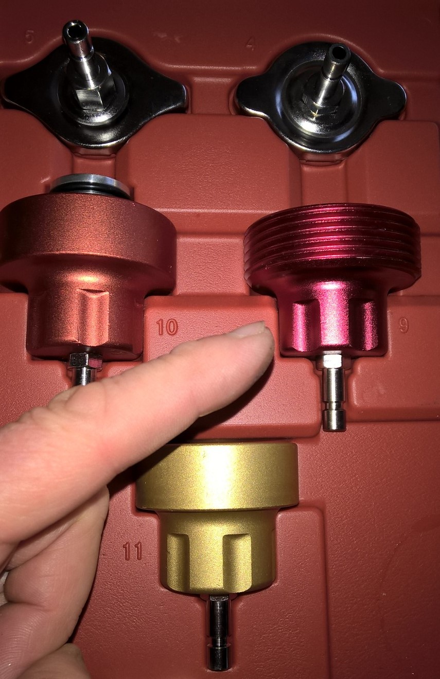
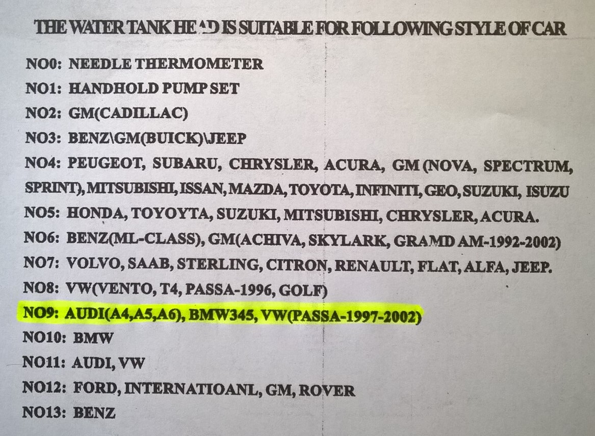
Cayenne 2003 4.5S I needed to pressure test my coolant system to identify a leak that, when hot, could be smelt but not seen & when cold didn't leak! I wanted to buy a Coolant Pressure Test Kit but was not sure which one to buy. During my research, I noticed there was one type of generic non-branded 'universal' kit that appeared multiple times on the general market (eBay & Amazon for instance).. Most listing for this generic kit listed all the car types it would fit but of course, Porsche was not listed - however, a few VAG applications were listed so I took a punt & ordered one of these kits for UK £45.00. The good news is that one of the VAG adapters supplied (#9) fits the Cayenne the header tank & I was able to perform the test on my cold engine & immediately, the leak was apparent. The purpose of my ramblings here is to share with you the kit I bought & the adapter used so you don't have to guess & take a chance as I did. I hope this helps someone. BTW, finally my luck ran out - it was my original plastic coolant pipes that gave up the ghost (there can't be many 2003 models out there still running their original plastic pipes)
4 points
-
You would need to get in line, others have been there before you. Mityvac, amongst others, have promoted this concept for years. Unfortunately, there is are a couple of major downsides: Going in through the dipstick tube, you rarely get all the old, contaminated oil out. Secondly, and perhaps more importantly, there are a lot of sharp edged things down there that can catch flexible tubes inserted down the dipstick tube. We have had more than one car flat bedded to the shop after an oil extraction unit line got stuck and could not be removed, requiring us to run up some expensive shop time getting it out. If you cannot get under the car and change the oil, or are uninclined to do so, take it to a shop and let them change the oil as the car was designed to do. In the long run, you will save yourself headaches and expense.4 points
-
The P1123 Code "Oxygen Sensing adaptation range 1 Cylinders 1-3) Lean limit" is referring to the fact that DME has reached its limit is trying to lean out that bank and the car is running too rich as the result. Usual two suspects are either high fuel pressure or a leaking injector(s) on that side. As you have not identified your year or model, in some cases is can also be a defect fuel pressure regulator on the injector fuel rail, depending upon the year, as some models do not have the external regulator. There is little probability of the MAF being involved in this issue. Step number one should be to get a fuel pressure reading off the test port on the fuel rail, should be 55+/-3 PSIG engine off; 48+/-3 PSIG engine running. If it is an early car with an external fuel pressure regulator, pull the vacuum line off the regulator and read the vacuum on the line, should be around 15 inches of vacuum. Checking the individual injectors is a bit more difficult; for a DIY, probably the easiest approach is to pull all the plugs on that bank and check their color. If one or more are overly dark, those would be your suspect injectors.4 points
-
Here's the video. Sorry for the shakiness and poor audio. I found my old 24-bit PCI soundcard isn't supported in Windows 7, and I've yet to invest in a new USB recording system. I only make these when something on my car breaks, so if anyone else in the Houston area wants to collaborate, I'll be happy to assist and film your next project.4 points
-
I did this over the weekend, so I videotaped it. My apologies for the narration. I need to not drink beer while editing. Hope this helps somebody.4 points
-
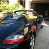
2003 Boxster - Purchased new in December '02 with mileage from the Port to my dealer here in So Cal (17 miles). I just changed my oil at 135,000 miles yesterday. I've only performed standard maintenance and do most of it myself: Oil and Filter (Amsoil 5W-40/Mahle Filter) every 15K Front Brakes - 60K Drive Belt - 60K Front and Rear Brakes - 120K Drive Belt - 120K Clutch as not been replaced on the vehicle. I have had to have my key reprogrammed on a couple of occasions over the years. I also had to purchase the shroud that must be removed to fill the transaxle twice due to road debris. I drive the car daily here in Southern California and drive a windy mountain road called the Ortega Highway to get from Southern California Wine Country to Orange County. I seem to replace the rear tires every 25K to 35K (I dumped the Pilots on my first tire change for a better wearing tire). Fronts about every two sets of rear tires. Best car I've every owned. It's my daily driver and runs incredible. Other than rock chips on the front from Southern California freeways, you would think the car had 20K miles on it. I just got in from the store...top is down and it's a beautiful day here today. Must be back in the 80's...heading back out to grab some carne asada for the barbecue. B) All the best, Bill_SoCal (Murrieta, CA) 2003 Boxster 2006 Cayenne 2008 Cayenne S4 points
-
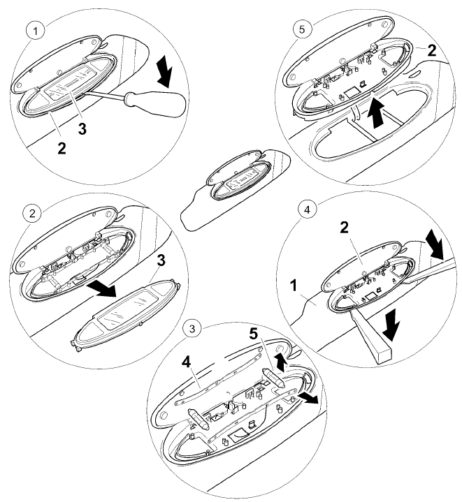
Because of the demand for disassembling sun visor - here it is: 1. Unclip mirror insert 3 -- Insert a narrow screwdriver between the mirror insert 3 and the mirror housing 2 at the bottom center, and unclip the mirror insert. 2. Remove mirror insert 3 -- Pull the mirror insert 3 upwards and remove from the mirror housing 2. 3. Remove bulb 5 and contact clips 4 -- Remove the 12V /3W bulb 5 from the contact clip 4. Take the contact clips upwards out of the holder. 4. Unclip mirror housing 2 -- Insert a narrow plastic spatula between the mirror housing 2 and the sun visor 1 on the left and right and unclip the mirror housing. 5. Remove mirror housing -- Take the electric lead out of the mirror housing 2 and detach the mirror housing from the sun visor.
4 points
-
For MY99 Boxster
4 points
-
I would add the following to help others attempting this ... please read the above and the below completely BEFORE starting your work. You'll thank yourself ! Getting the tank out I'd remove the air pump instead of tying it to the side as above. Its very simply and takes 30-40 seconds. It gives you room you REALLY need. Plus you won't break the air hose by bending it too much. NOTE: There are two screws that hold the air pump in place - at the bottom. In my case I found out that the nut thse screws go into had fallen off during removal. The nuts are 'suspended' in a rubber tube and age/temperature had made the rubber brittle and the nut had just fallen when I took the screw out. I simply got new speed nuts (2x : part number: 999.500.078.00 : $2) and used them to fit the air pump back again. Its worth taking the air pump off even if you now need to buy $2 more of nuts when ordering your tank - it gives you a lot of room you need ! To remove the coolant reservoir easily out of its harness, slide it towards the engine (i.e. move right) by around 1/2 to 1 inch. Then move it DOWN and out of its rail/holder. There is no need to slide it COMPLETELY (3-4") towards the engine completely as it first appears. The railings have tabs and gaps to facilitate such removal/installation. You probably won't even have that much room to slide it out completely ! When draining the coolant from below the car, you'll need a bucket to keep most of the coolant and may need to empty the tray below into the bucket. Use 2 trays so you can empty one when the other is below the car. The coolant drains fast, so you can't use just one without making a mess. Also, there is a lot of coolant, almost a bucketfull. Coolant is a corrosive liquid - keep it off the paint. If you drop some on the paint, don't panic, just wipe it off with water and a cloth. Use gloves if possible. The drain plug for the coolant is close to the rear bumper, don't search too deep inside near the transmission etc ! There is a coolant level sensor at the bottom of the coolant tank. Its deep and tough to see and you may break it manupulating the tank of get it out of the engine compartment. I'd recommend you reach down and remove it as follows. - when reachable, turn the sensor by 1/4 turn from towards you to towards the engine. - pull the sensor out from the bottom (it needs 2" to fall out, its 2.5" tall). - keep it somewhere ! If you do break it (likely), its around 10-18 bucks, so don't panic ! Lastly, be patient in getting the tank out. Its not difficult but simply time consuming. Be careful not to bend/break other hoses while you try getting the coolant tank out. Putting the new tank back in place When installing the new tank, I found it easy to first install the sensor at the bottom and then twist-lock it (1/4 turn). The electrical connection should point towards the right taillight. First try to get the entire tank in the volume reserved for it in the engine compartment. Don't try to directly fit it in. Make sure you don't leave any tubes/connectors behind the tank during installation. The last think after installation is to realise you need to get it out to rescue a forgotten tube. Now you want to get the tank back in its harness. The harness' as well as the tank's railings have gaps to ease removal/installation. What worked good for me was rotate the tank anti-clockwise by 10-20 degrees when inside the cavity/volume of engine compartment position the right most tab of the tank sticking out of the harness while keeping the other two tabs (on the tank's top) positioned to fall in the gaps between the harness' tabs. Try feeling the gaps with your finger to know where the tank's tabs should land. Slide a 1.5" diameter metal tube at the bottom (running front -> back) slightly to the left (or right?) so that the level sensor wouldn't be obstructed upon rotation. It should gently slide out of its holder. Now level the tank (i.e. rotate it clockwise by 10-20 degrees). The tank's tabs should have fallen where the harness' gaps are and the tank will be one tab sticking out (out = towards the engine) Finally move the tank gently away from the engine, in its final installed position [*] Slide the metal pipe back into its clamp [*] Connect everything else just the reverse as removal. After everything is installed Once you have the new tank in place, you will need to refill it with coolant and 'bleed' the coolant system. Fill the coolant tank with existing/new (porsche recommended) coolant to the max level and close the coolant tank lid. I simply filtered my existing coolant with a old (but clean) cotton t-shirt and poured it in using a funnel. Then, to quote Loren, "Lift the bleed valve." "Start the engine and allow it to get to full operating temperature (I also ran the air conditioning to force circulation). The coolant warning light will likely start to flash. Shut the engine off and WAIT until the engine and coolant has cooled enough to remove the coolant tank cap. Then add coolant to the tank and repeat the process. You made need to do this 2-3 times. When the coolant level fails to fall then the system is bled and you can close the bleeder valve." About bleeding the coolant system. Close the bleeder value after about 40 minutes (total) of good driving. You shouldn't ride with it open for more than this (my Porsche tech told me this). You MUST wait for the coolant to cool between your 2-3 tries, else you won't be filling the tank completely (coolant contracts as it cools). I've had to wait for over 3 hours to cool. If you try before this then the coolant will spill off when you open the cap. You may get a coolant light even with the bleeder valve closed after a few days. This is ok and doesn't mean you cracked your tank or something again. Basically there was some air trapped and the car "burped" it into the coolant reservoir, triggering off the coolant light. Wait for 4 hours for the car to cool and then top off with coolant+water (replacing a lot) or just water (replacing just a little). If even after 3-4 top offs/"burps" you need to keep adding coolant, have it checked for other leaks in the coolant system. In the end, once you've done it, please pat yourself on the back !! Great job :thumbup: !! Even my service tech. at the local dealership said its not a simple job. Its worth doing it on your own if you suspect you're losing coolant. :cheers: Sid
4 points
-
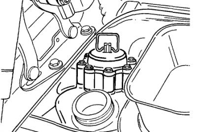
If the oil cap is hard to remove, you have a high vacuum level in the sump, which is bad for a variety of reasons, including lean stalling. The correct way to access the AOS is to fully warm up the engine by driving the car for 10-15 min, then replace the oil cap with the one in the picture above with a hose that connects to the digital manometer. If the vacuum level exceeds 6-7 inches of water vacuum, the AOS is leaking air into the intake system, causing the lean stall conditions. The normal level of vacuum is typically 4-5 inches of water, which is a really weak vacuum level, so it doesn't take much of a leak to cause problems, which is why we always checked every car that passed thru the shop with the manometer.3 points
-
It's is used at the assembly line/factory, not used by PIWIS or anything, has a data line from the DME only though that can carry the same info from DME, but no other data lines included in it like the PIWIS/OBDII connector.3 points
-
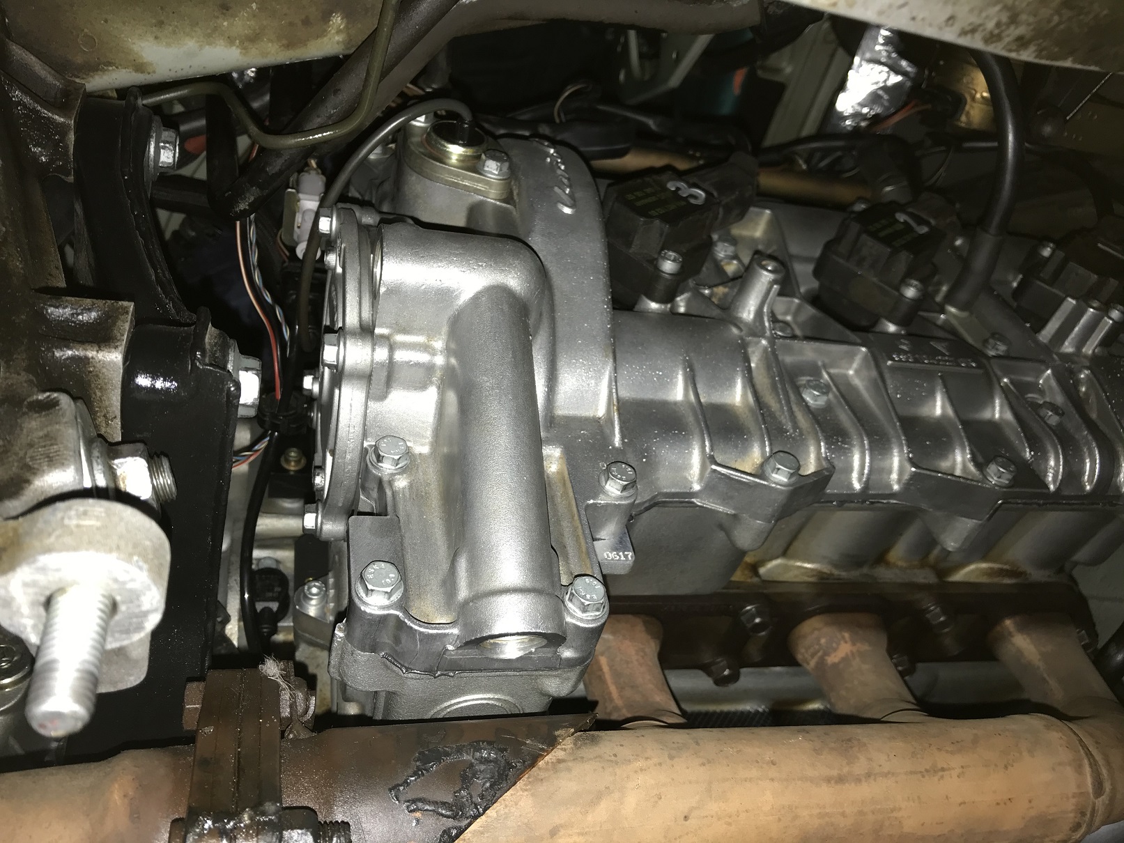
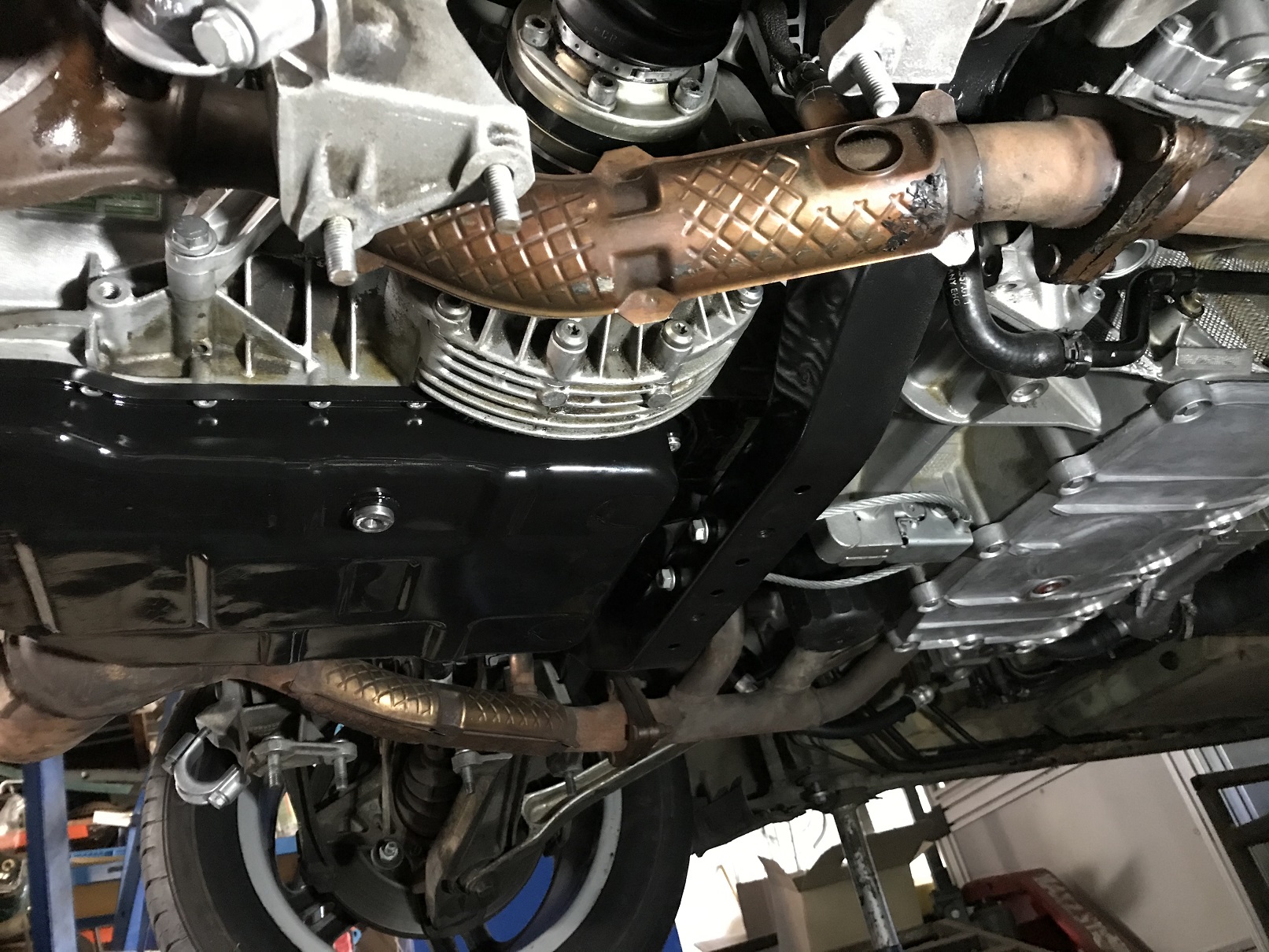
In case it helps someone else in this situation, I discovered removing the fan and shroud allows sufficient access to remove the pump. This means no radiator work is needed besides the shroud removal. Should I need to drain or remove the rad in the future, I'll just take off the fan housing (and trust me, that's not a fun job, either!) You then then have access to the lower radiator hose to release the clip.3 points
-
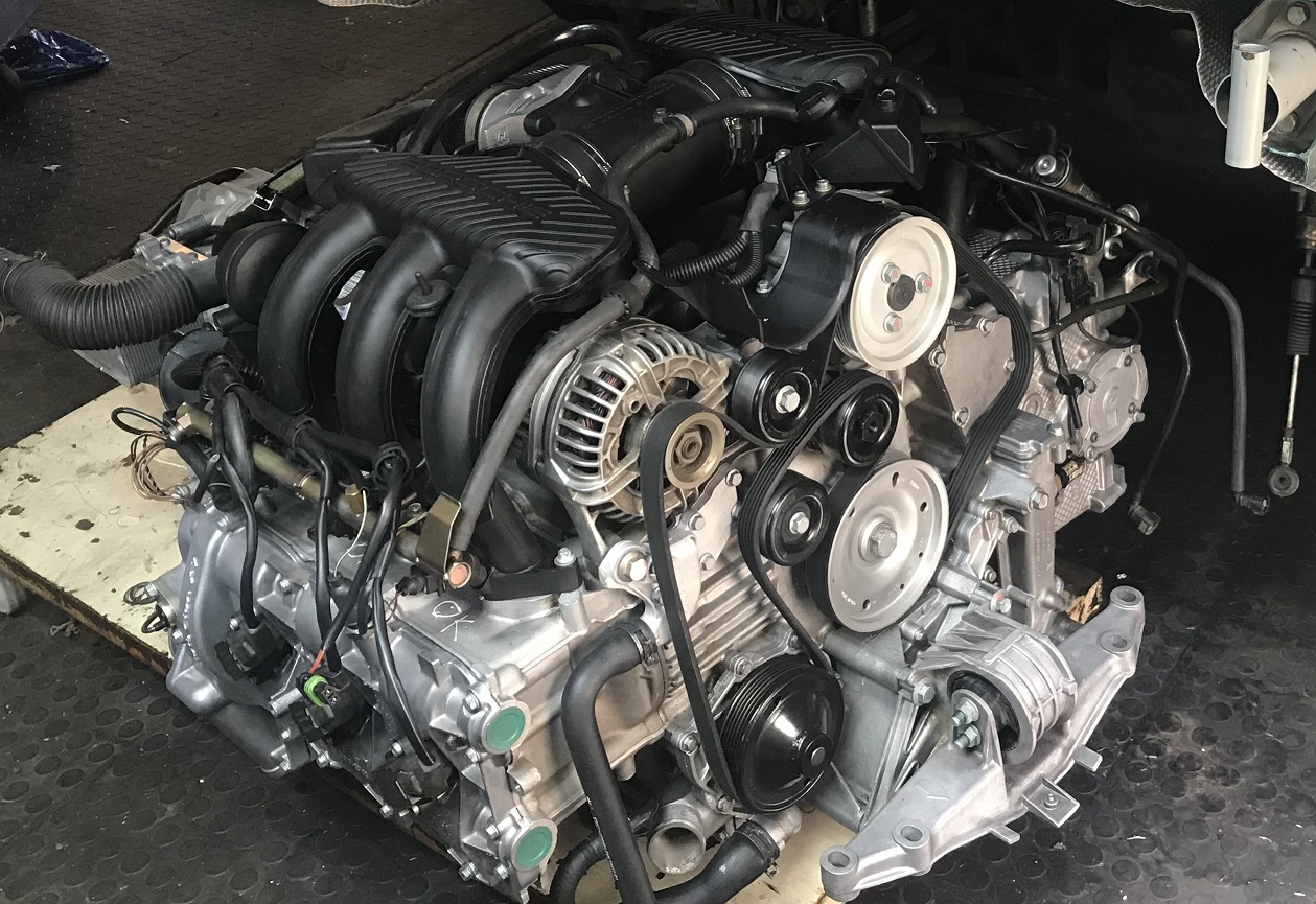
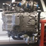
Some after photos... Definitely took more time cleaning than building this motor....
3 points
-
You can get a set of small "ez out" hex bits, one of which should fit tightly into the bolt head while rotating counter clockwise, which will loosen the stripped fastener. Amazon and others sell them (Amazon screw/bolt extractor set)3 points
-
I recently decided to place some bright white LED's in both the driver's side and passenger's side footwells of my '98 Boxster. The lights are super thin and come with a 3M adhesive. I placed the driver's side LED strip on the vent tube that runs horizontally and the passenger's side LED strip accross the bottom of the footwell foam cover in the natural grove channel. The foam cover is held in place by 2 screws with large heads. Both sets of lights are wired together and are joined together on the passenger side above the foam cover (and now new LED light) and connect to two (2) wires, positive and negative, that run up the passenger's side "A Pillar" trim piece, then accross the top and connect to the center interior light. The positive is soldered into the "Y" shaped copper rocker inside the light switch and the negaitve is wire tapped into the center wire entering the switch. It has the same off/on properities as the door lights with the added flair of manual on/off by turning on the center interior light. The center interior light and now footwells can be always on, always off and door and locking activated. Here is a shot of the driver's side in my darken garage.3 points
-
I had the same problem. There is a rubber coupling between the motor and window cable drive pulley. The rubber softens with age to the point where the window barely moves when the handle is operated, however when the window is fully opened or closed everything appears fine. The mechanism can be stripped very easily, I made replacement rubber coupling inserts just using a Stanley knife and 8mm rubber gasket material. The end result was a perfect cure that cost pennies.3 points
-
I recently successfully self-diagnosed and repaired the A/C on my Cayenne. Total cost for parts and refrigerant ~$65. Vent temps went from 17 C before the fix to 4 C in ~24 C / 75 F ambient temps and high humidity. I will post details on the fix and the way to diagnose this particular problem (and other HVAC issues) in a new thread. Anyways, one thing I discovered is that there is a lot of incorrect information out there regarding the HVAC system on these cars. One of the more pertinent items: The Cayenne uses a variable displacement compressor with an electronic compressor control valve for modulating the mass flow of refrigerant through the compressor. There is no compressor clutch, so to speak. This is not like the old compressors that we are all familiar with that use an electric clutch to cycle the compressor ON/OFF. Please gently slap anyone who talks about an electric clutch on the Cayenne compressor. If you are in doubt, just do a google search for "Cayenne AC compressor" and look at the pictures. There is only a single electrical connector and it routes to the back of the compressor; this is the compressor control valve. The HVAC control unit adjusts the refrigerant flow to meet the required demands. Instead of cycling a clutch on and off, a swashplate inside the compressor adjust the stroke of the compressor pistons to realize the specified refrigerant mass flow. No more ON/OFF cycling, just nice consistent cooling--in theory, at least (and when everything works). Fuse 11 that Loren mentions powers the compressor control valve. The negative lead goes to the HVAC control unit. The valve is driven by a PWM signal, likely current controlled. To the OP (Bichito): Sorry to say it, but your compressor is toast. The part that you are referring to as a clutch is actually a sacrificial break-away mechanism. The idea is that if the compressor locks up then this part will break in two and allow the pulley to spin so that your other accessories are still driven. I can think of no other scenario for your situation other than a catastrophic failure of the compressor. If you are lucky, then the compressor didn't spit it's guts throughout your refrigerant system. Either way, you will need a new compressor (and drier, at a minimum) and a very thorough cleaning of the refrigerant system (get this part wrong and you may be doing the whole job over again). Sorry... @neoplanet: Your problem may be far less serious but we need more information. You wrote that the A/C shop said that everything checked out OK. What does this mean? I'm assuming that this at least means they did a visual inspection of the A/C compressor and did not see anything obviously wrong (like what Bichito found). Did they give you any pressure numbers? Do you get any cooling whatsoever? You wrote that they said there was no voltage going to the compressor. I'm not convinced they checked this correctly. First of all, hopefully they realized that the connector they were looking at was for the compressor control valve (not a clutch, as it doesn't have one). According to the manual that I have, +12 V should be on the red/white wire. Now, if they disconnected the connector and attempted to check the voltage across both leads then they would likely run into a problem because 1) the valve is controlled by a PWM signal (you need an oscilloscope, not a multimeter) and 2) the control valve is most likely current controlled: if you take the valve (which is low impedance) out of the circuit then the computer will recognize this as a problem and probably will not drive the line low. I would totally expect them to find 0 V if they tested things this way. You can test the +12V wire by connecting one lead of a voltmeter to the red/white wire and the other lead to anywhere on the car that is grounded. To properly test that the electronic signal to the valve, you need to keep the valve in circuit and probe across both wires with an oscilloscope. Frankly, I wouldn't waste my time doing this at the moment. First thing I would do is get some pressure readings. If your high side pressure is OK then you can forget about the electrical checks on the control valve. Once I know your pressure readings I can make a suggestion as to what I would check next. Brett p.s. To address the original question, there is no A/C relay on the Cayenne and therefore no "A/C relay location". :) Edit for clarification: I should have said that there is no "A/C compressor clutch relay". I also just noticed that this thread was a year old. Oops!3 points
-
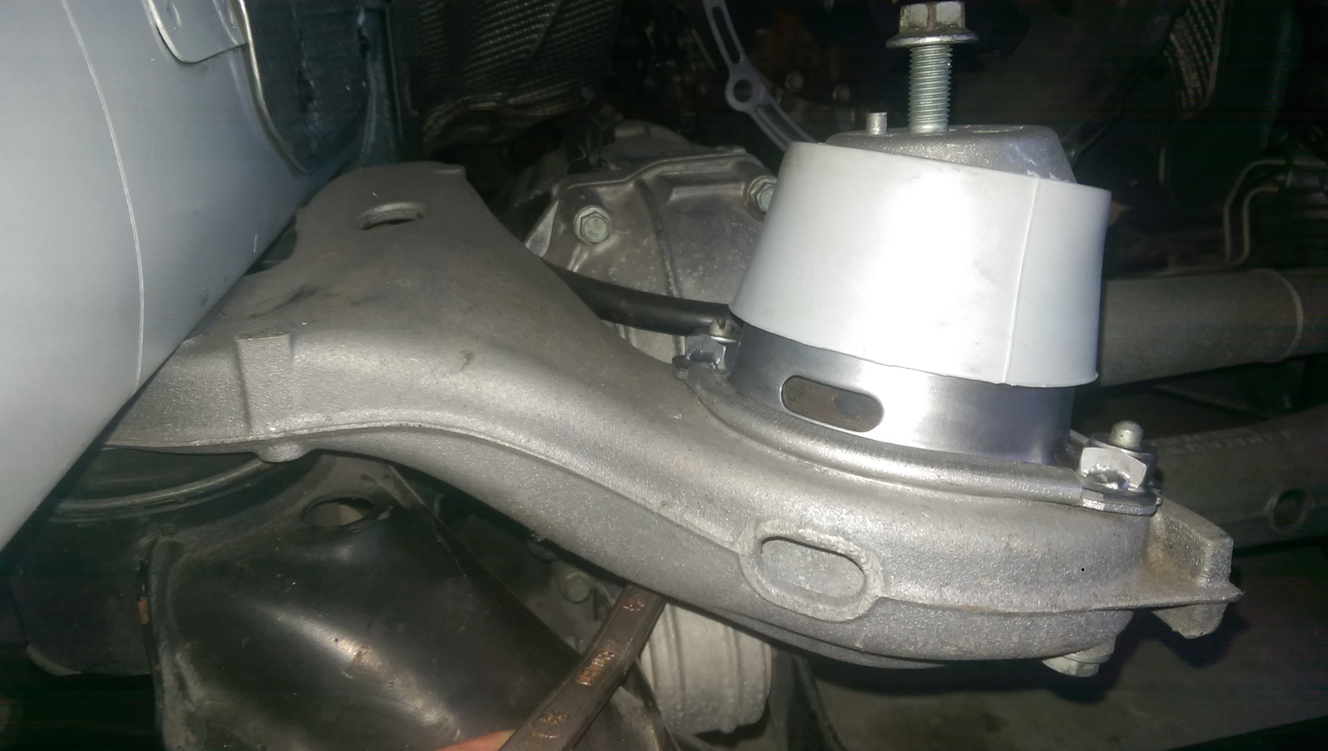
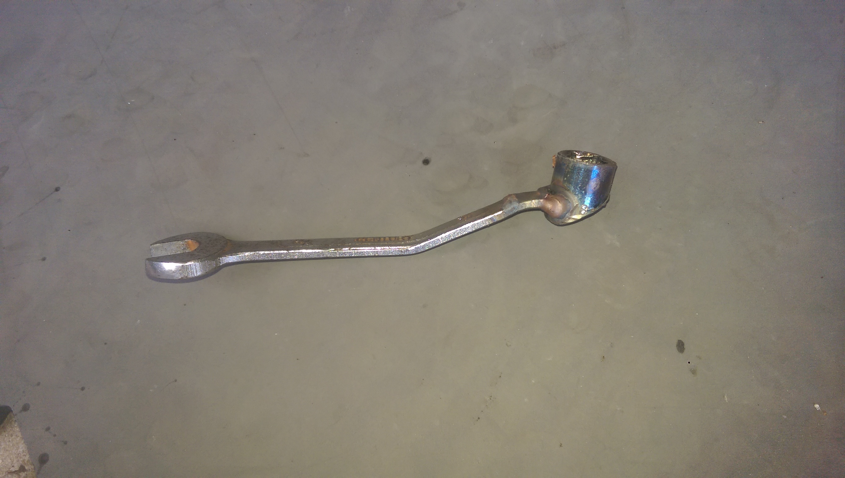
Yes. But the bolts are difficult to get from underneath. I tried bending an end wrench and ended up making one by welding a socket to a cut off end wrench and grinding some away. The mounts drop by about 3/4 of an inch with wear.
3 points
-
Welcome to RennTech I can tell that your mechanic does not specialize in Porsches. This is a topic that has been discussed many times, and a good search would help you fill in the details. In a nutshell, cold air systems are a waste of time and money on these cars as it came from the factory with a very well designed one already installed. Your current fuel injectors are capable of delivering more than enough fuel, so putting in larger ones is also a general waste of time and money. They also won't add anything as the DME will step in and throttle them back to maintain the correct A/F ratios. The next big "fix" to produce more power are the aftermarket reflashes of the DME, which typically produce increases that fall with in statistical error range of the factory output on a dyno. Larger throttle bodies and trick intake plenums also add little if anything on the dyno. The best suggestion I would give to you is to remain very circumspect of performance gain claims you see in internet ads for companies that sell these mods; most are pretty much hot air. So the question becomes how to get more power; the unfortunate answer is to spend a lot of money. These engines are a system and need to be approached as such. It is very possible to generate a lot of power, nearly twice the factory output, but it comes at a stiff price: Approaching $20K for a completely redone engine out of one of the premier M96 engine builders.3 points
-
Coolant Pipe Replacement Detailed Instructions I recently replaced the coolant pipes in my car. I needed to do the job myself because there was simply no way I was going to shell out anywhere from $1500 to $3500 in labor to have it done by the dealership or an independent shop. Plus, having read about the job, I knew they would be tearing through a ton of stuff and I really feared the "oh, it also needs this" scam. I did a LOT of research on the various forums before undertaking this job. Reading and printing out anything I thought was Author Harness Category Cayenne (9PA, 9PA1) - Common Fixes and Repairs Submitted 06/11/2011 05:39 PM Updated 03/14/2017 07:05 AM3 points
-
Recently PCA posted attempt to accommodate 996 owners who may be frustrated with value and IMS controversy. We're aware of the class action suit won against Porsche regarding the original IMS. Also, it's recommended that we replace the original IMS anyway and don't know how to determine if it was defective to begin with. There's a company publishing on Facebook, believe called Gearheads, that put the 996's as one of 8 sports cars that, if bought, should be done with extreme caution. Some of PCA comments included that maybe 1 of 10 996's may experience IMS failure (local dealer told me maybe 1 of 100 and part of problem due to lack of mileage accumulation) and 9 of10 potential buyers have issues with IMS controversy. Not very helpful from my perspective. Another engineering problem is with pinion gear in 2d gear of manual tranny. I've replaced IMS and installed new tranny. Assume there were at least 50k of this model sold and, if so, a lot of potentially frustrated owners. Acknowledge that some non 996 owners response might be we had a choice. MY car's been for sale and can only tell prospective buyer the replacement IMS warranty was only for 30 days. I'm preparing to discuss this at future PCA meets and seeking comments.3 points
-
So, again in an effort to help others that might look for this in the future: 996 GT3, Airbag Light and Durametric fault " Code 30, ignition circuit - side airbag, passenger". Side airbag = door airbag: There was nothing wrong with it, the connector was good, and I also electrically swapped a spare airbag that I had, but the fault remained. Knowing the issue was coming from that circuit, and since I had disconnected the door and the controller when I stripped the car, I looked at both of those, looking for a bent pin, or? I expected the door connector to be the bad player since it's a bit less straightforward to connect and disconnect than the controller. While trying to identify the relevant pins on the big connector at the door jam to wring out the wires, I noticed that, with the connector off, the two pins/wires for the door airbag were shorted together (no doubt a shunt to prevent accidental airbag deployment when the connector is not connected). I also noticed that, in the connector, right next to the two pins, there was a small rectangular slot that matched a small plastic piece on the mating connector. At first I thought that it was an alignment device, but there was more to it than that, because there was a small piece of metal in the slot. While ohming the two airbag pins, I shoved a pick in the slot and suddenly, the two shorted pins/wires were no longer shorted, meaning that THE PLASTIC PIECE HAS TO BE ALL THE WAY INTO THE RECTANGULAR SLOT so that the circuit is in an acceptable state for the airbag controller. So again, even if the connector appears to be connected, you need more than just the pins to be in contact, you need the plastic tab to be all the way in to the slot. These pins and slot are part of a sub-connector within the main door connector and the sub-connector is somewhat free to move a bit. I made sure that it was all the way in and now my airbag light is gone. I'm sitting in the car with the laptop, having gone back in with the Durametric to clear the code, and decided to tell my story. Hopefully it can help someone. Case closed :)3 points
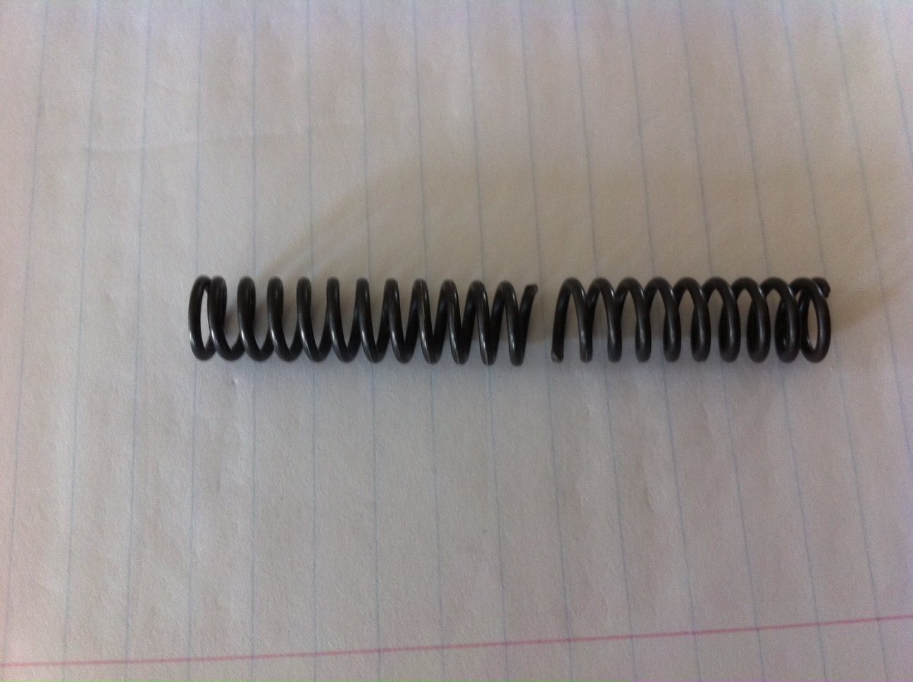
-
I hadn't driven the car lately and took it out for a spin. After it warmed up, I stretched it's legs until the speedo pegged stupid, then i eased out of it for a mile or so and exited the highway. When I got to the intersection the oil pressure lamp lit up and i noticed it was about .3 bar. I could hear my sphincter pull my Levi's into my collon. A quick blip of the throttle brought it back up to 1.5, where it mostly stays. Even cold it doesn't usually make it over 3. So I headed to the house and hit this forum to find what I thought was my best guess as to what is causing this. The top choices seemed to be switching to the hotly contested "right" oil viscosity or a collaped or improperly fitted oil filter. I considered both of these causes and the bad charma my wife continues to throw at me and this car because she just doesn't get it. The correct answer turned out to be the bad karma. She caused the low pressure piston spring to break in the middle and the movement/vibrations allow it to thread itself back together to make a half as long - twice as strong spring, and that apparently will cause low pressure pretty much all the time. I ordered the part from the stealership $8, bought a cool new hat, and once it came in I swapped the springs. It took me little more detective work to find the bolt the spring goes over but once I did it is a 60 second swap. BTW, you can let out a lot of oil in those 60 seconds so be ready. That fixed it. 5 bar at start up, 1.5 at idle, and 3-5 going running thru the gears. I'm willing to bet there are more of these worn out springs/bad wife karma combos out there so now you know. Maybe the brighter already knew.
3 points
-
To anyone who is following this topic: It CAN be done and is not as nearly complex as you might think. After my initial post I received an email from another forum member. He informed me that he had done the swap successfully a couple of year ago and that while it was not bolt on/plug and play, it was by no means as difficult as the internet would have you believe. He was amazingly helpful during the process and the only reward he wanted was knowing that another 3.6 swap would be done. I am currently driving the car with no issues, it has terrific power & drivability and I could not be more happy with it. There is one tiny trick he revealed that when you hear it, it makes all of the sense on the world and it solves the programming issues between modules, the key transducer and the immobilizer which in turn solves the problem between VarioCam & VarioCam+. We are going to post a write up on the swap procedures so that others can do it with the same success. What I liked best about the process was that there were no "workarounds", aftermarket pieces or hacks needed to make it work, it is all 996 and is very straightforward. Please note: we are not doing this for any kind of reward or fee, we are just so pleased that it can be done that we will share it with the forum, and that should happen soon.3 points
-
My 996tt Key is just too badly abused to be used lol So SunCoast Porsche Dealer was kind enough to honor the PCA discount and sent me the NEW design KEY which is an easy gut swap from old to new! As this process went on you can really see and feel why they went with a new key design. New weather seal design is much better and and the construction is 100% more solid. Of course its light years more pleasing to own. Box Old Key New Key Old and New OPENed Up Remove the Transmitting Crystal Pull back this Clip and this one Pull out the Circuit Pull the woodriff key out that is sitting on a spring to release the pressure on the key blade it self Pull and you have one dirty key... Clean the Key Blade using metal polish and bronze wire brush (bronze so you don't scratch the key blade when cleaning.) LOTS of dirt from the keyblade! So fresh and clean your Key Blade will be Don't forget to clean the tract ... do it right! Plug it into the same spot but on your new Key New All rubber pad in the new key Plug things back in old & new New Key with Crest Key Chain The BEST part of it All.3 points
-
I've added a new section to the OBD II section that gives a table of Porsche System Tester(s) codes and their cross-reference to P-Codes. Useful when the service technican gives use a two or three digit code that is not a (Standardized DTC SAE J 2012) P-Code. This listing is also useful to related P-Codes, to determine fault types and whether the MIL (CEL) light on, off or flashing with a specific code.I think I transferred everything ok but let me know if you see typos or other mistakes.Porsche OBD II P-Codes Section3 points
-
This has been covered before, but it can be done using a 4" diameter plastic pipe coupler (has a ridge half way down the inside that the old flywheel bolt heads can rest on, then tighten slowly in a crosswise pattern to pull it in evenly.) The trick to getting the new design PTFE seal to work where the older design did not is being absolutely scrupulously clean, not even finger prints on any parts, and no sealant of any kind. You also have to install it at an unusual depth, 13MM from the flywheel mating surface of the crank, not 14MM.3 points
-
Both the RMS and IMS appear to show different levels of leakage; the RMS is seeping, the IMS flange is flat out leaking. I would definitely install a new PTFE style seal; at around $20, it is a no brainer. The IMS flange is leaking the worst. Probably none of them unless they show signs of a problem. The reason Porsche came out with replacement bolts had to do with the RMS bore concentricity or roundness. Back when they were replacing entire engines due to leaks that could not be stopped, Porsche came out with slightly longer microencapsulated bolts to replace the four in the bell housing area to try and hold the RMS seal bore in a more stable position during engine operation. These were typically applied to the early M96 engine's that had shorter bolts from the factory. Unfortunately, while they may have stopped the leaks in some cases, Porsche eventually figured out that the real issues were out of round RMS seal bores, and variances in the concentricity of the flywheel flange on the crank. To help the dealers decide which engine's could be saved by retrofitting rather than replacement, Porsche released special tool 9699/1, which became known as the "Go, No Go gauge". When inserted over the crank flange and into the RMS opening of the cases, if this tool touched the RMS bore edge or showed the case bore and/or crank flange was off visually center, no retrofit of bolts or a new seal was going to save the day and the engine had to be replaced. So it is more than just the bolts, but as Porsche also began using the longer bolts in regular production engines, most of the later engine's already carry them, and replacing them with new versions of the same bolt really does not accomplish anything. The IMS flange would get new bolts, however. Your current RMS (part number 997.101.212.00) is the PTFE unit, which was introduced in 2005, so yours must have been changed at least once. The IMS "part number" you have noted is for the rear flange only, not the IMS itself. But I would ask one question concerning the IMS in the engine: What size socket fits on the center bolt nut in the flange?3 points
-
Well thanks for the comment. I figured a way to get the Reservoir out and it indeed did leak from the seam at different locations. Received the parts and coolant within a day, and re-assembled the whole thing yesterday. The system is not leaking anymore, and the remaining task will be to find a place to get old coolant disposed before I can replace it. Overall I split the job over 2 vacation days, where-off most of the time I did spend analyzing function of components and how things are assembled and of course removing more parts then needed. Looking into these things is always interesting and entertaining to me since I normally analyze very complex systems on the nano-scale while getting hands off the computer keyboard and some physical workout hanging under the car for free. However, as a car non-expert I always wish to find more information on rather trivial looking steps, and since I could find nothing specific about the reservoir replacement , I compiled a picture documentation of how I did the 2006 CTTS coolant reservoir replacement job. Hope this might be useful for others too.3 points
-
Well, we had another round of rain of biblical proportions last night (inches in an hour sort of rain..) so this AM I checked the P!G. I found the floor wet again. Not as wet as prior wetness, but for sure wet. I pried up the carpet and the foam was again wet, but it appeared my drain had worked, the wet wasn't up as high, and not as much got wet. Spent some quality time with towels wringing out the foam and drying it off again. So - it appears that heavy rain causes the leak (and perhaps the HVAC contributed..) So I started tearing things apart looking for the source. I first popped off the fuse cover and the trim next to it on the starboard side, to find: Hmm.. drips. Then I looked further and saw: More drips. They're appearing from behind the A-pillar trim piece (at the top of the photo..) The drips appeared to be travelling down the inside surface of the A-pillar inside trim. The path followed down past the fuse box and behind the right side kickpanel under the dash, right into the foam backing of the carpeting. I decided to look further upstream. To do so - I had to remove the A-pillar trim. This is actually rather easy. I had already popped off the little trim piece near the fuse box cover, and I went looking for what holds the A-pillar trim in place. Found it - one long T25 screw under the "AIRBAG" logo on the trim: After removing this screw, you can easily pull the trim out from the top down - pull it toward the center of the windshield to release some stab-clips on the back, and it then slides up and out from next to the dash. Quite easy actually (and a good time to tidy up any wiring that had been tucked behind it.) There is a side-curtain airbag there, so use a bit of caution (don't jam screwdrivers willy-nilly in behind it.) This is what's found once that trim is removed: You can see the path the drain hose takes. It's quite well protected, and there was no sign of leakage on the outside of the hose, so I suspected that up higher in the hose wasn't a problem (but decided to look anyway.) I next took the trim piece off the sunvisor mounting and two T20 screws behind it, which allows pulling the headliner corner down a bit. The actual mount stays attached to the headliner and no wiring has to be disconnected. If I could have figured out how to remove the passenger assist handle in the roof I could have pulled the headliner down even further, but as was, it came down far enough that with a Maglite LED flashlight I could see the hose all the way into the drain fitting for the sunroof drain: All looked good on the drain hose. No tears, no sign of wetness. I went up top, opening the sunroof and looking around, and found there was leaf-munge in the drain area and on the tracks of the sunroof mechanism. I used my high-pressure air-gun to clean the crap out (after using my fingers to get the big stuff out - and there was some crap blocking the drain.) It turns out, if the drain is plugged and enough water gets into the area (I did an experiment with a pitcher of water), it will overflow around the edge of the sunroof, and the headliner happily routes it right down the A pillar trim with the plastic backing of the trim keeping it flowing nicely down past the fusebox and out eventually to soak the floor. Lesson - clean sunroof drains. I blew them out, then checked again with a pitcher of water, and the water happily ran out the bottom of the truck, and none appeared along the drain line, or dribbling down the headliner. Here is the rough location of the drain as seen from up top. It's actually almost (not quite, but almost, you'll need a good Maglite to see it) impossible to see due to the wind-dam popup in the sunroof housing. While I was in the area, I cleaned up the fuzzy edge of the sunroof gasket (it had hardened munge on it) and where it meets the body (which also had hardened munge on it) in the hope that the gasket seals better. I'm awaiting the next rainstorm (doesn't look like it will be a real long wait - probably tomorrow) to see if this actually helped anything. Thanks to RFM for suggesting I check the sunroof drain. Biggest trick is getting so you can see it.3 points
-
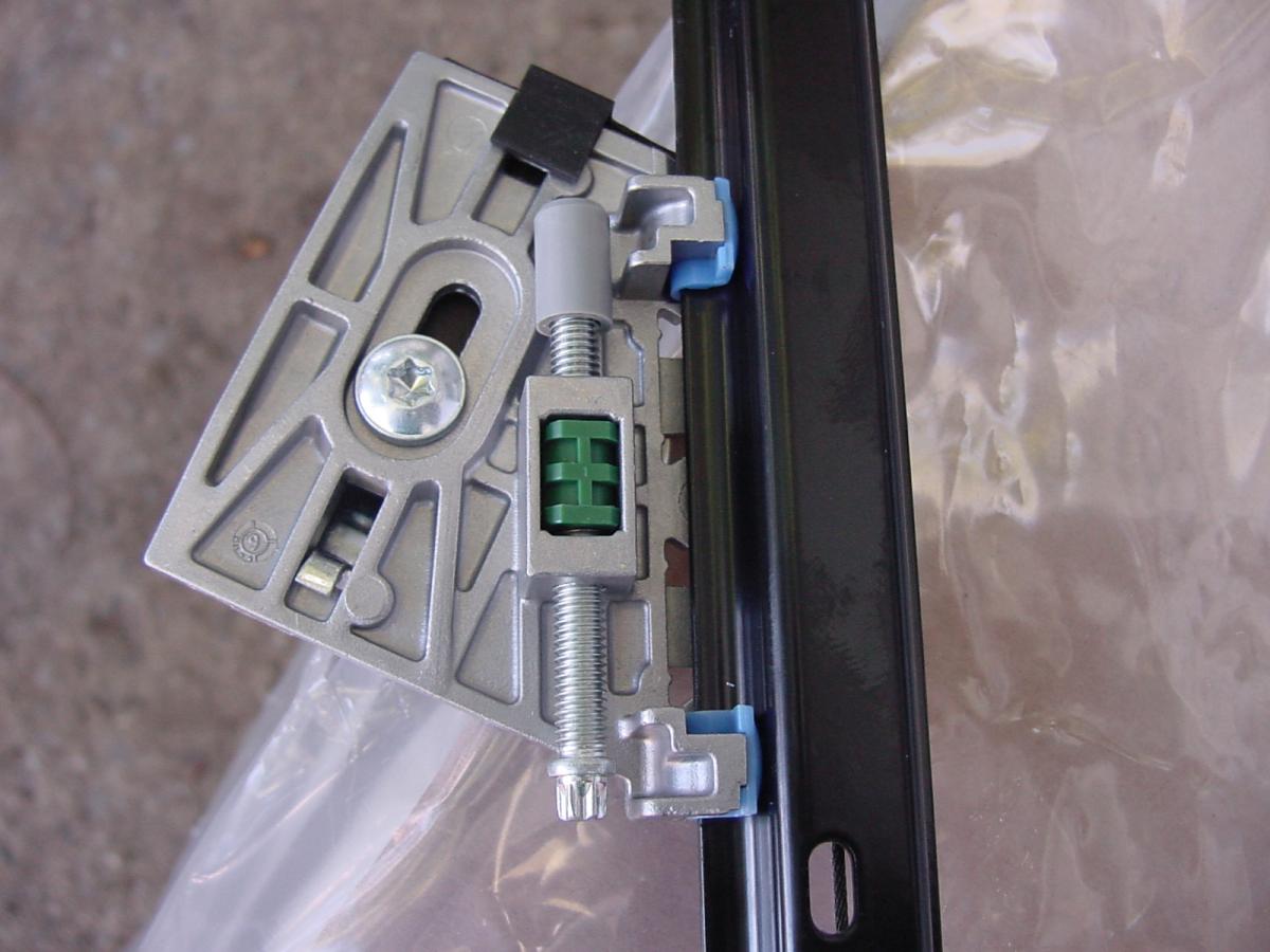
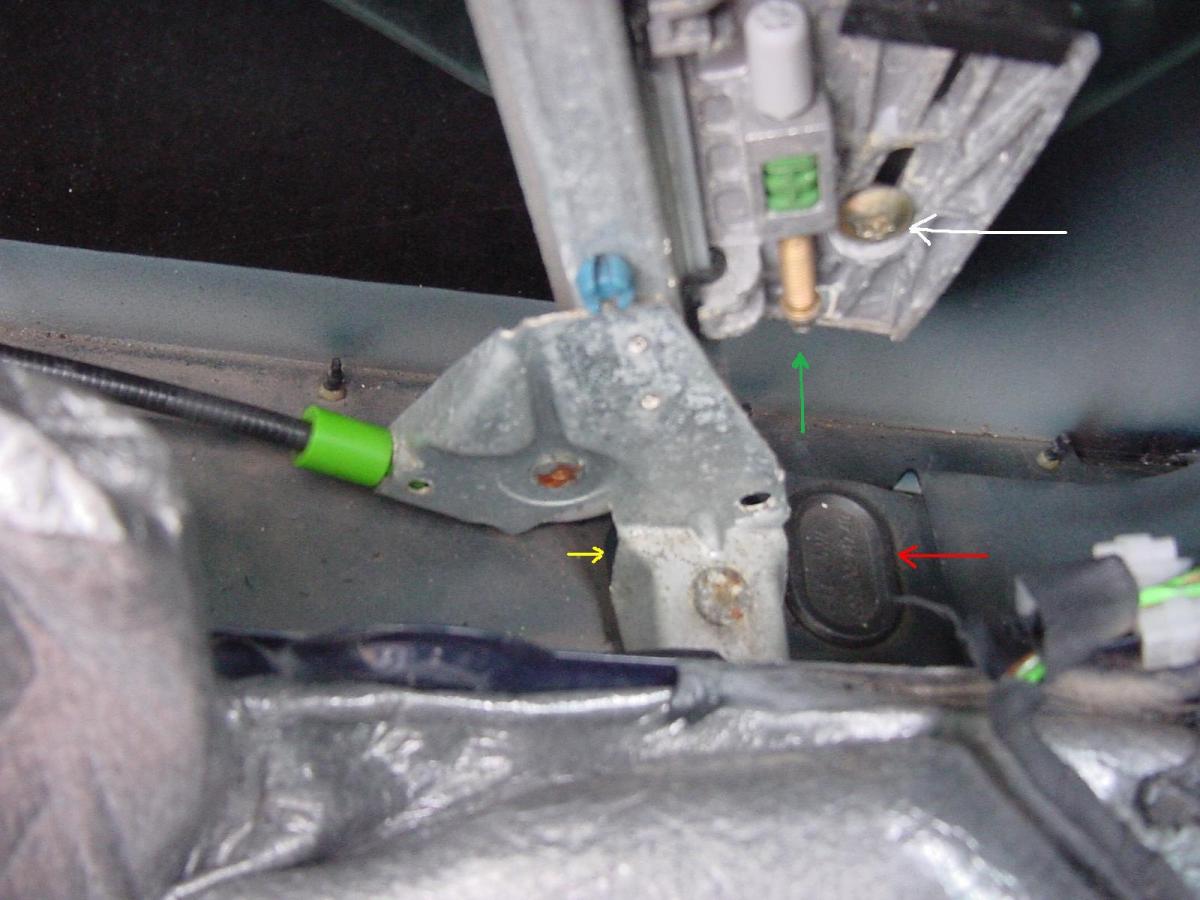
There are three possible adjustments to the position of the windows: 1) inboard/outboard, 2) up and down at the front of the window and at the back of the window, and 3) forward and backward. The access holes on the underside of the door are two near the front edge of the door and two near the rear edge of the door. The ones closest to the front edge and rear edge of the door are for accessing the adjustment for 2) above. The ones furthest from the front edge and rear edge of the door are for accessing the adjustment for 1) above. To perform the adjustment for 3) above, you must remove the door panel to get access to the window regulator glass clamps. Here is a photo that will help you visualize what you are dealing with (click to enlarge): Note that this is the forward leg of the window regulator for the driver's side door (left side) from a 986, but it's the same setup for a 996. 1) The yellow arrow points to the very edge of the access hole black rubber plug for adjustment 1) [inboard/outboard]. That adjustment is accomplished by loosening the 10mm nut that is on the opposite side of the stud whose flattened head can be seen at the foot of the regulator leg. When you loosen the nut, the stud can be moved inboard and outboard and that affects the inboard/outboard position of the window when it is closed. 2) The red arrow points to the access hole black rubber plug for adjustment 2) (up and down final position of window when it is closed). To make that adjustment, pull off the rubber plug and insert a socket with an extension to turn the torx head screw to which the green arrow is pointing. Clockwise will lower that side of the window, CCW will raise that side of the window. You can raise or lower the front of the window with the torx screw in this photo, and raise or lower the rear of the window with the torx screw that is on the rear leg of the window regulator. Even though it's a torx bolt, a 5 mm socket will work. 3) The white arrow points to the screw that tightens the rubber-lined metal clamp that holds the glass window onto the window regulator. There is one metal clamp on each of the two window regulator legs. In order to perform adjustment 3) [forward/aft], you must remove the door panel to get access to that screw on each of the two clamps. Once you loosen each of the two screws, you can move the glass forward and backward, enough to fix the problem described in the first post. Be careful not to overtighten the clamp because it is squeezing the glass through the rubber pads. Here is a closeup of the window regulator torx screw and window clamp to help you get oriented: Regards, Maurice.
3 points
-
Hi All, I've located the problem, quite simple really apart from the lack of space behind the dash. I located the servos, there are three I could see, and one under the dash controls the recirculation system. one nearest the shifter is the footwell, there’s one a little further up I assume that’s for the face vents or windscreen. In order to access the servos first remove the bottom panel, one torx screw nearest the seat in the centre, then drop the panel down & detach the 12v aux sockets (there’s 2 on mine). Also detach power from the footwell light. Then remove the glove box, very simple just a few screws then is drops away. Then you can see more. If you follow the wires you see the servos, all 3 are the same basic type. 3 screws hold each one on, that’s the more tricky part as they are fiddly, but once the servo is off you can test it. Mine was dead, but once I worked it a little it jumped into life, maybe it was jammed. I them popped the cover off and you can see inside, there’s a little motor in there and a few contacts, I cleaned it all up with contact cleaner lubricated it and reassembled it. Then hey presto I had a blast of air in the footwells. So that’s the first time for 4 years +, and the dash didn’t have to come out, thankfully. If it fails again I'll get a new solenoid, I think now I know I could replace it in 15 minutes. Hope this helps someone else, regards James3 points
-
The keys for these cars are a reoccurring theme: Expen$ive. They require a special (read expensive) tool to cut, which many locksmiths do not have. I am not aware of any aftermarket source for the blanks. The coding is an issue because it requires proprietary software (PIWIS) to accomplish. Unfortunately, for the most part, only the dealer network has access to all three components, which limits your options. You can try shopping around different dealers, they often vary widely on what they charge, but in the end you are probably going to have to pay more than you want to get it. Not that it will make you feel any better, but we went through a similar process to get a second key for a customer’s Nissan; the key was $150, the programming was another $95, and everything was “dealer only” for the same reason as Porsche: The market is too small for the aftermarket to tool up and do it for less.3 points
-
After reading this forum on Saturday, I went about replacing my amber side markers with clear side markers. After partially removing the wheel well liner like this forum and the owner manual suggests I struggled to remove the first side marker. After about 20 minutes, the first amber marker was out. What a chore. Now that I could see specifically how and where the marker attached (with pressure clips) I decided to take a different approach on the second side... 1. Slip a piece of fishing line (I used 40lb test) under the front point of the side marker. You may have to put a little pressure on top or bottom of the lens to free up a gap to get the line completely under the point of the light. 2. Carefully work the line back from the point 1/2 to 3/4 inch toward the center of the light. 3. Holding both end of the fishing line, give the line a firm tug, not too hard. This will unclip the lens form front pressure clip and partially from the rear pressure clip 4. Carefully remove the lens the rest of the way from the rear pressure clip and a slight tilt will also release the safety clip as well. 5. Remove the bulb from the amber lens, replace bulb with amber bulb, align slots on bulb gasket with clear lens align tabs on clear lens with pressure clips on vehicle and press lens into place. Total time expended on first side (using the owner’s manual method) 30 minutes by the time I put everything back together. Total time expense on second side 4 minutes. I hope this helps everyone save some time so you can spend less time with your hand(s) wedged up inside the fender well and more time behind the wheel.3 points
-
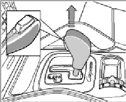
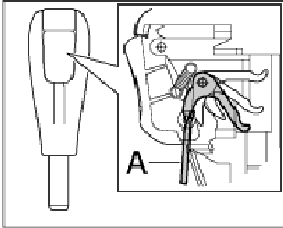
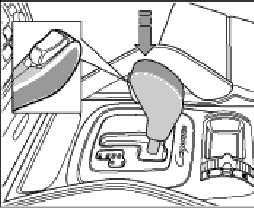
Removing selector knob 1. Selector lever is in position D. Note! -- The button (inset) at the front must not be pressed down when the selector knob is pulled. 2. Pull selector knob up and off. Installing selector knob Note! -- The button must not be pressed down when the selector knob is installed. 1. Selector lever is in position D. Caution! Spring in selector knob is overstretched! - Only move the selector knob as far forward until the tool can be inserted. - Avoid any further overstretching. 2. The unlocking hook in the selector knob must retract to the button grey object . Lock the hook under the button, using short screwdriver A for example. 3. Push on the selector knob until it audibly engages in the selector support. The sleeve is then inserted in the selector lever cover. 4. Remove the tool on the handle. 5. Functional test of gear selecting system: - Will the vehicle start? - Do all the selector lever positions work?
3 points
-
The famous plastic cooling pipes are indeed connected (push in) in to the thermostat housing, a small coolant leak at that spot drips into the V between both cylinder banks and evaporated before the coolant hit the floor, that could be the smoke you have seen. A leak on the water pump typically falls on the floor or the under tray.3 points
-
I change the driver side fuel pump (primary) last week end. If you need to drive the car and avoid to pay a towing, just remove the #1 pump relay in the engine compartment fuse box. You need a torx 30 because the relay is located in the hidden part right next to the firewall. If your car starts and stall in less than 30 secs... Remove the key, remove the #1 fuel pump relay, then restart the car. If the car still running after 30 secs, like me your primary fuel pump is defect. By doing this, the computer think there is no fuel on left side and run the secondary pump !!! I drove the cayenne about 60 miles with the second pump to the dealer to buy the fuel pump, small pipe and 2 seal because you need to open both side under the seat. The fuel pump have many pipe attached to it with different size and lenght to avoid bad connection. Two pipes are running from left to right. The job is not easy but you need to do it when the tank is almost empty or use a manual pump like me. Do it outside, the smell is horrible and take a tylenol. Dont forget to clean the fuel filter on the top plate driver side, I never seen so much black dirt in a small filter... I clean it 8 times in fuel bowl and reinstall it. I suspect dirt filter may cause the pump problem. To remove the bolt under the seat use M10 and they are very very tight and this is probably the biggest job to do. Then have a beer and congratulate you for saving 1,000$. I have all the pdf very helpfull if you want it, let me know.3 points
-
I have a 1997, which was the first year. It has been so long I do not remember all the details. The door lock thing I think was for model year 1998. In the US we did not even have a one touch up for the passenger window in 1997. That started in 1998. The window and top up thing started in 2002. I remember this because we took the top relay out of a 2002 and tried it on an older car. Did not work. Different control units. Live with what you have or buy a newer car..3 points
-
I know when I need technical information, I come to this board. So for all those who search the board for 997 air filter housing removal, hopefully they will find this thread...3 points
-
Harman = Becker
3 points
-
For those with the horn problem, I wanted to steer you towards the black hi temp silicone repair. I tried going to Lowe's, Home Depot, and even Ace for the o-ring solution suggested by jporter, but could not find an o-ring #38 or nylon washers of the right spec. Very frustrating. When I took off the airbag, I found that my rubber bushings were all still in place! This intrigued me because everyone else's had tears or even torn all the way through. Nevertheless, the silicone fix has solved my horn problem, and I conclude that my rubber bushings, though still intact, had become exceptionally flimsy, and unable to offset the airbag's weight. Good luck to others with this problem. James3 points
-
Removing: Lever the locking button A off with a suitable tool or finger. The locking button must be pressed so that the tool can be inserted between the selector lever B and locking button. (The ignition key must be in position 1 before the locking button can be pressed.) 2. Remove compression spring A and pull spring clip B off toward the rear. 3. Pull selector lever up and off. Installing: 1. Assemble the selector knob with spring clip, compression spring and locking button. Fit conical compression spring with the small diameter facing the guide peg.) 2. Press the complete selector knob onto the shift lever until it bottoms. The spring clip must fully engage in the slot on the selector lever. 3. Check function of locking button.3 points


.jpg.ad4981e16c92f2cd6d307408db757e45.jpg)